1
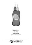
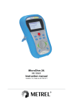
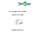
Insulation / Continuity Tester
MI 2123
User Manual
Version 1.1, Code No. 20 750 424
Distributor:
COSINUS Computermesstechnik GmbH
Lise-Meitner-Strasse 6
D-85521 Ottobrunn
GERMANY
Tel: 089/665594-0
Fax: 089/665594-30
http://www.cosinus.de
Manufacturer:
METREL d.d.
Ljubljanska cesta 77
1354 Horjul
Slovenia
web site: http://www.metrel.si
e-mail: [email protected]
Mark on your equipment certifies that this equipment meets the requirements of the EU
(European Union) concerning safety and electromagnetic compatibility regulations
© 2000..2007 METREL
No part of this publication may be reproduced or utilized in any form or by any means
without permission in writing from METREL.
2
MI 2123 Insulation / Continuity
Table of contents
1. General introduction --------------------------------------------------------------------------------4
1.1. Features---------------------------------------------------------------------------------------------4
1.2. Applied Standards --------------------------------------------------------------------------------4
2. Instrument description -----------------------------------------------------------------------------5
2.1. Instrument Casing --------------------------------------------------------------------------------5
2.2. Operator’s Panel ----------------------------------------------------------------------------------5
2.3. Connectors -----------------------------------------------------------------------------------------6
2.4. Bottom Section ------------------------------------------------------------------------------------7
2.5. Accessories ----------------------------------------------------------------------------------------7
3. Warnings and Instrument Messages ----------------------------------------------------------8
3.1. Warnings--------------------------------------------------------------------------------------------8
3.2. Instrument Messages----------------------------------------------------------------------------8
4. Measurements -------------------------------------------------------------------------------------- 10
4.1. Insulation Resistance -------------------------------------------------------------------------- 10
4.2. R ±200mA -------------------------------------------------------------------------------------- 12
4.3. Continuity ----------------------------------------------------------------------------------------- 14
5. Operation with Results--------------------------------------------------------------------------- 16
5.1. Storing of Measurement Results------------------------------------------------------------ 16
5.2. Storage Handling ------------------------------------------------------------------------------- 17
5.3. Data Transfer ------------------------------------------------------------------------------------ 20
6. Maintenance ----------------------------------------------------------------------------------------- 21
6.1. Inspection----------------------------------------------------------------------------------------- 21
6.2. Battery Replacement -------------------------------------------------------------------------- 21
6.3. Fuse replacement ------------------------------------------------------------------------------ 22
6.4. Cleaning------------------------------------------------------------------------------------------- 22
6.5. Service -------------------------------------------------------------------------------------------- 22
7. Specifications --------------------------------------------------------------------------------------- 23
7.1. Measurements----------------------------------------------------------------------------------- 23
7.2. General specifications ------------------------------------------------------------------------- 24
3
MI 2123 Insulation/Continuity Tester
General introduction
1. General introduction
1.1. Features
The SMARTEC Insulation / Continuity Tester is a portable hand-held battery powered
test instrument intended for testing of safety measures on mains installations. It
operates on a SIMPLE and CLEAR basis.
The equipment is designed and produced with the extensive knowledge and experience
acquired through many years of dealing with electrical installation test equipment.
General functions of the SMARTEC Insulation / Continuity Tester:
- Insulation Resistance measurement,
- Continuity measurement using test current of 200 mA in accordance with EN 61557
standard,
- Continuity measurement (continuous measurement) using test current of up to
7 mA,
- AC / DC Voltage and Frequency measurement.
Features:
- Wide range of Insulation Resistance test voltages (50 up to 1000 V DC),
- Automatic discharge of tested item after measurement completion,
- Automatic test voltage polarity exchange in Continuity ± 200 mA function,
- Continuity 7 mA function for inductive test items,
- Memories,
- PC connection.
A custom designed LCD offers easy to read results. Operation is simple and clear, the
operator does not need any special training (except reading and understanding this
Users Manual) to operate the instrument.
In order for the operator to be familiar with measurements in general, it is advisable to
read the handbook Measurements on electric installations in theory and practice.
The instrument allows storage of test results. Professional PC SW enables simple
transfer of test results and other parameters in both directions between the tester and
the PC.
1.2. Applied Standards
Instrument operation:
IEC / EN 61557-1, IEC / EN 61557-2, IEC / EN 61557-4
DIN VDE 0413-1, DIN VDE 0413-4, DIN VDE 100
BS 7671 – 16th edition
Electromagnetic compatibility (EMC): IEC 61326, Class B
Safety:
EN/IEC 61010-1 (instrument),
EN/IEC 61010-2-31 (accessories)
4
MI 2123 Insulation/Continuity Tester
Instrument description
2. Instrument description
2.1. Instrument Casing
The instrument is housed in a plastic casing, which maintains the protection class
defined in general specifications. The casing consists of a main section, which includes
the operator's panel and connectors and of a flexible cover.
Note! The cover is permanently fixed to the base section and cannot be detached.
2.2. Operator’s Panel
The operator’s panel consists of a custom LCD, a rotary switch, and a keyboard, see
the figure below.
1
1
2
2
8
3
3
4
7
5
6
4
5
Fig. 1. Front panel
5
6
7
8
MI 2123 Insulation/Continuity Tester
Instrument description
Legend:
1.......... Custom designed LCD.
2.......... Up key to increase storage group.
3.......... START key to start any measurement.
4.......... DISP key to display subresults of selected function.
5.......... MEM key to store and recall results.
6.......... CLR key to erase memorized results.
7.......... Down key to decrease storage group.
8.......... Rotary switch to select measurement function.
2.3. Connectors
Use originl test accessories only!
Max. allowed voltage between mains test terminals
and ground is 300 V!
Max. allowed voltage between mains test terminals
is 600 V!
Max. output voltage between test terminals is 1100 V!
1
1
2
3
Fig. 2. Connectors
Legend:
1.......... Test connector.
2.......... RS 232 connector to connect the instrument to PC.
3.......... Battery charger connector.
Test connector is intended for connection of the test cable and is accessible only when
the instrument cover is lifted up. RS 232 and battery charger connectors are accessible
only when the cover of the instrument is closed. For safety reasons both connector
fields cannot be accessible at the same time, the cover of the instrument selects the
accessible one.
6
MI 2123 Insulation/Continuity Tester
Instrument description
2.4. Bottom Section
1
2
DISCONNECT ALL TEST LEADS AND SWITCH OFF THE INSTRUMENT
BEFORE REMOVING THE BATTERY COVER - HAZARDOUS VOLTAGE!
DO NOT CHARGE IF BATTERY COMPARTMENT CONTAINS ALKALINE CELLS!
3
POWER SUPPLY:
4
VOR OFNEN DES BATTERIEFACHS ALLE ZULEITUNGEN VOM GERAT
ENTFERNEN UND DAS GERAT AUSSCHALTEN - GEFAHRLICHE SPANNUNG!
NICHT AUFLADEN WENN ALKALZELLEN VERWENDET SIND!
4 × 1,2 V - NiCd, NiMH RECHARGEABLE (IEC LR 14)
or 4 × 1,5 V ALKALINE BATTERIES (IEC LR 14)
STROMVERSORGUNG:
4×1,2V - NiCd, NiMH AUFLADBAR (IEC LR 14)
oder 4×1,5V - ALKALZELLEN (IEC LR 14)
5
Fig. 3. Bottom section
Legend:
1.......... Plastic housing.
2.......... Screw (4 pieces) to fix the battery cover.
3.......... Battery compartment cover.
4.......... Battery cover warnings.
5.......... Trade mark label.
2.5. Accessories
The instrument consists of standard and optional accessories. Optional accessories can
be delivered upon request. See attached list for standard configuration and options or
contact your distributor or see the METREL home page: http://www.metrel.si .
7
MI 2123 Insulation/Continuity Tester
Warnings and Messages
3. Warnings and Instrument Messages
3.1. Warnings
In order to reach highest level of operator’s safety while carrying out various
measurements and tests using the SMARTEC Insulation / Continuity Tester, as well
as to ensure the test equipment remains undamaged, it is necessary to consider the
following general warnings:
•
•
•
•
•
•
•
•
•
•
If the test equipment is used in a manner not specified in this Users Manual,
the protection provided by the equipment may be impaired!
Do not use the instrument and accessories if any damage is noticed!
In case of blown fuse, follow the instructions in this Instruction Manual to
replace it!
Service intervention or calibration procedure is allowed to be carried out
only by a competent, authorised person!
Consider all generally known precautions, in order to avoid risk of electric
shock while dealing with electrical installations!
Use only standard or optional test accessories supplied by your distributor!
! symbol at the instrument means “Read the Users Manual with special
care!” The symbol requires an action!
! symbol on LCD indicates that the measurement results show an irregular
condition of the item under test which may present a hazardous live voltage.
Disconnect all test leads and switch power off before opening Battery cover!
Do not charge when alkaline batteries are fitted!
3.2. Instrument Messages
Messages are generated on the LCD using special symbols and numeric segment
combinations. The next figure shows all possible display segments and the table under
the figure describes the messages.
Result value
Low battery
Higher than
Unit of displayed result
Warning!
Operation with storage
Cursor to indicate
compensated test leads
Mains voltage present
at test terminals
Fig. 4. Display segments
8
MI 2123 Insulation/Continuity Tester
Warnings and Messages
Description of possible display messages:
>1999
FUS
SEr
rES
End MEM
MEM
no MEM
rCL
Clr flashing
Clr / ALL alternating
Result over range.
Blown fuse in Continuity functions only.
Active serial communication.
*Reset of the instrument (erased memories).
All storage locations occupied.
Operation with storage (store or recall).
No result to be stored or no stored result to be recalled.
Recall function is entered.
Confirm or abort clearing of last stored result?
Confirm or abort clearing of all stored results?
Table 1. Messages
Note!
• * This indication appears after the first insertion of batteries, i.e. when there were no
batteries in the battery compartment for a specific period of time (a few hours), or if
the microprocessor detects an irregular state in its memory or if reset of the
instrument has been performed.
9
MI 2123 Insulation/Continuity Tester
Measurements
4. Measurements
4.1. Insulation Resistance
Warnings!
• Make sure that the item to be tested is disconnected (mains voltage
disconnected) before starting the Insulation Resistance measurement!
• When measuring Insulation Resistance between conductors, all loads must
be disconnected and all switches closed!
• Do not touch tested item while the test is in operation, risk of electric shock!
• Do not connect test terminals to an external voltage higher than 600 V AC or
DC in order not to damage the test instrument!
• In case of capacitive test item (capacitive compensation of reactive power,
long tested cable etc.), automatic discharge of the item may not be done
immediately after finishing the measurement. Falling voltage will be displayed
in that case – do not disconnect test leads until the voltage drops below 50 V!
The following figure shows connection of the instrument to tested item for testing of
Insulation Resistance on electric installations. The measurement should be carried out
between all conductors.
RCD
L1
L2
L3
N
PE
PE N
L3 L2 L1
Fig. 5. Connection of the instrument to item under test
There may be also other items to be tested such as motor windings, ground cables,
antistatic floor coatings, walls etc., see the booklet Measurements on electric
installations in theory and practice
10
MI 2123 Insulation/Continuity Tester
Measurements
How to carry out the measurement:
- Connect test leads to item to be tested in accordance with figure 5.
- Select Insulation resistance function using appropriate test voltage by means of
rotary switch knob.
- Press the START key and keep it pressed until the result has stabilised then
release the key. With pressing the START key twice successively, continuous
measurement starts to run.
- Read displayed result (Insulation Resistance).
- Check subresult (Actual test voltage) by pressing the DISP key.
- The result can optionally be saved using the MEM, Up and Down keys, see
instructions in paragraph 5.2. Storage handling.
MΩ
V
Example of displayed
Insulation Resistance
Actual test voltage
Fig. 6. Example of displayed result
Notes!
• If an external voltage higher than 30 V AC/DC is present at test terminals, the
Insulation Resistance measurement will not be carried out after pressing START
key but the voltage will be displayed marked with ! symbol.
• Tested item is discharged automatically after finishing the measurement and the
actual voltage is displayed during discharge operation (only if high capacity is
present).
• Positive pole of test voltage is attached to red test terminal.
11
MI 2123 Insulation/Continuity Tester
Measurements
4.2. R ±200mA
Continuity of protection conductors is to be measured, before mains voltage is
connected to tested installation (new or adapted installation). Max. allowed resistance
value depends on power of connected loads, used installation system (TN, TT) etc.
Test current of at least 200 mA is required by the EN 61557 regulation which is why this
function is to be used whenever tests are to be done in accordance with this standard.
For additional general information concerning Continuity measurement, refer to the
handbook Measurements on electric installations in practice and theory.
Warning!
• Make sure that the tested item is de-energised (mains voltage disconnected)
before starting the measurement! Fuse will blow if test probes are connected
to mains voltage during the test.
How to carry out the measurement:
- Connect test leads to tested item in accordance with the figure below.
- Select R ±200mA function by means of rotary switch knob.
- Make sure test leads are compensated, see the instructions in the next chapter.
- Press the START key and release it. To ensure the instrument’s protection this
function enables individual measurements (the START key should be pressed for
each measurement).
- Read displayed result (Continuity), see figure 8.
- The result can optionally be saved using the MEM, Up and Down keys, see
instructions in paragraph 5.2. Storage handling.
RCD
L1
L2
L3
N
PE
PE N
Fig. 7. Connection of test leads
12
L3 L2 L1
MI 2123 Insulation/Continuity Tester
Measurements
Ω
Comp
>
Fig. 8. Example of R±200mA test result, test leads are compensated
Notes!
• If an external voltage higher than 10 V AC/DC is present at test terminals, the
R ±200mA measurement will not be carried out after pressing START key, but the
voltage will be displayed, marked with ! symbol.
• If test result is out of measurement range (open test leads), >1999 Ω message will
be displayed!
• If indication FUS appears, replace blown fuse with new one. See the paragraph 6.3.
Fuse replacement.
Compensation of test leads’ resistance
In order to achieve high accuracy of test results it is advised to compensate resistance
of the test leads before carrying out Continuity measurement. Especially it is advised to
compensate test leads whenever the leads are changed for different ones.
How to compensate test leads:
Select R ±200mA function.
Short out test leads.
Press the START key twice successively, total value of measured resistance
(resistance of test leads + internal resistance) is displayed for a while then 0.00 Ω is
displayed. Cursor symbol on display (see the fig. 4) shows compensation state.
Resistance of test leads is therefore compensated and the instrument is ready for
Continuity measurements.
Notes!
• Max. resistance that can be compensated is 5 Ω. If total measured resistance is
higher than 5 Ω (e.g. open test leads) then any compensation previously stored is
ignored (compensation indicator disappears).
• Compensation of test leads’ resistance can be done only in the R±200mA function.
• The indicator for compensation of test leads appears only after compensation has
been performed and remains until the compensation is cancelled (e.g. by performing
the compensation at open test leads).
• Compensation of test leads’ resistance is stored and is used for both R ±200mA and
Continuity functions.
13
MI 2123 Insulation/Continuity Tester
Measurements
4.3. Continuity
Continuity function is intended to be used when there are inductive loads to be tested,
for example motor windings, transformers etc. or if there is no need to follow prescribed
standards. It can be used also as an ordinary multi-meter (resistance range). This
function enables continuous measurements (the measurement is running continuously
after pressing the START key).
Test current of only up to 7 mA is used in order to save the battery energy.
For additional general information concerning Continuity measurement, refer to the
handbook Measurements on electric installations in practice and theory.
Warning!
•
Make sure tested item is de-energised (mains voltage disconnected) before
starting the measurement! Fuse will blow if test probes are connected to
mains voltage during the test.
How to carry out the measurement:
- Connect test leads to tested item.
- Select Continuity function by means of rotary switch knob.
- Make sure test leads are compensated.
- Press the START key and release it, measurement starts to run continuously.
- Press the START key again to stop the measurement.
- Read displayed result (Continuity), see the figure below.
- The result can optionally be saved using the MEM, Up and Down keys, see
instructions in paragraph 5.2. Storage handling.
Comp
>
Fig. 9. Example of Continuity test result, test leads are compensated
Notes!
• If an external voltage higher than 10 V AC/DC is present at test terminals, the
Continuity measurement will not be carried out after pressing START key, but the
voltage will be displayed marked with ! symbol.
• Compensation of test leads’ resistance can be carried out in R ±200mA function only.
• If test result is out of measurement range (open test leads), >1999 Ω message will
be displayed!
• If indication FUS appears, replace blown fuse. See paragraph 6.3. Fuse
replacement.
Positive pole of test voltage is attached to red test terminal.
14
MI 2123 Insulation/Continuity Tester
Measurements
4.4. Voltage Measurement
How to carry out the measurement:
- Connect test leads to equipment under test.
- Select VOLTAGE function by means of rotary switch knob.
- Press the START key, continuous measurement starts to run.
- Read displayed result (Voltage), see the figure below. Displayed voltage may be
exchanged with frequency by simply pressing the DISP key at any time, even whilst
the measurement is running.
- Press the START key again to stop the measurement.
- Check subresult (Frequency of displayed voltage) by pressing the DISP key.
- The result can optionally be saved using the MEM, Up and Down keys, see
instructions in paragraph 5.2. Storage handling.
V
Hz
Displayed result
Frequency
Fig. 10. Example of voltage measurement result
Note!
• Do not connect test leads to a voltage higher than 600 V AC, to avoid possible
damage to the instrument!
15
MI 2123 Insulation/Continuity Tester
Operation with Results
5. Operation with Results
5.1. Storing of Measurement Results
The memory for storing of measurement results has a stacking group organisation. The
operator has the possibility to organise 1999 groups. Each group has the possibility to
stack any measured result. In ‘storing result’ mode the operator selects a group and
then the result is stacked together with all its parameters into the selected group. The
figure below shows a graphic presentation of result grouping.
Rm
Ri
R2
R1
G1
G2
G3
.....
Gn
.....
G1999
Fig. 11. Storage locations organisation
A set of information stored on location Ri (main result, sub-results and parameters)
depends on selected function. There can be many results stored on the same location.
Practical Example of Storage Organization
For example: There is a standard house installation that has to be verified with regard to
various electrical characteristics. The test plan should be prepared before any
measurement is taken. The plan is based on wiring schematics and contains group
definitions e.g. floor, room, wall socket and the related measurements in each group.
The groups are assigned with numbers from 1 to 1999. When the test plan is defined
the operator starts to run the measurements from group to group. The instrument asks
every time for the group when storing test results. The result can be simply stored into
the appropriate group if the group number already corresponds to selected
measurement place in test plan, or the group number can be changed first and then the
result stored.
All results can be stored under a single group, e.g. No.: 1, if there is no need for
grouping.
16
MI 2123 Insulation/Continuity Tester
Operation with Results
5.2. Storage Handling
The following keys are intended to be used for storage handling: MEM, ↑, ↓ and CLR.
There are the following possibilities of handling:
To store
result (result
is displayed):
a) Press the MEM key after completing the measurement. Last used
group will be offered automatically, see the figure below.
b) Use ↑ and ↓ keys to change group number.
c) Press the MEM key again to store result.
MEM
Offered group number
MEM
Once stored - no possibility
to store the same result again
Fig. 12. Group code and reaction to double storing of the same result
Notes!
- Press the START key or change rotary switch position to cancel
store procedure.
- Each result can only be stored once.
To recall
stored
results:
a) Press the MEM key just after changing rotary switch position, MEM
mark will appear on LCD and rCL for a moment followed by the last
accessed group number.
b) If there is no stored data no and MEM will flash for a second
followed by selected function idle state display.
c) Use the ↑ and ↓ keys to change the group number.
d) Press the MEM key again once appropriate group is selected to
recall stored result. If there is no result stored in selected group no
and MEM will flash followed by the group number.
e) Use the DISP key to check sub-results and parameters.
f) To see previous or next stored results inside selected group press ↑
or ↓ key. Every entry is followed by the function code and then the
result.
g) Press the MEM key to change group number and go to b).
Note!
- Press the START key or change rotary switch position to cancel
recall procedure.
17
MI 2123 Insulation/Continuity Tester
Operation with Results
Indication when entering recall
procedure
MEM
Last accessed group is offered
MEM
Storage buffer empty
Code of stored function (rotary
switch position 7 = R±200mA)
MEM
Ω
Stored result (R±200mA)
MEM
Fig. 13. Displayed information during recall procedure
To clear
complete
Memory:
a) Exit storage operation (storing or recalling), press the CLR key and
keep it pressed until Clr and ALL messages start to alternate then
release it.
b) Press the CLR key again to erase all stored results.
MEM
MEM
Fig. 14. Waiting for confirmation
Note!
Press the START key or change rotary switch position to cancel clear
procedure.
18
MI 2123 Insulation/Continuity Tester
To clear only
last stored
result:
Operation with Results
a) Exit storage operation (storing or recalling), press the CLR key, Clr
message appears, then release the key.
b) Press the CLR key again to erase last stored result.
MEM
Fig. 15. Waiting for confirmation
Note!
- Press the START key or change rotary switch position to cancel
clear procedure.
Stored Parameters
The following is a list of results, sub-results and parameters stored for each function.
Function
RINS 50 V
No
1
Stored data
Function code
Insulation resistance
Actual test voltage
Function
RINS 1000 V
RINS 100 V
2
Function code
Insulation resistance
Actual test voltage
CONTINUITY 6
Function code
Resistance
RINS 250 V
3
Function code
Insulation resistance
Actual test voltage
R±200mA
7
Function code
Resistance
RINS 500 V
4
Function code
Insulation resistance
Actual test voltage
VOLTAGE
8
Function code
Voltage
Frequency
19
No
5
Parameters
Function code
Insulation resistance
Actual test voltage
MI 2123 Insulation/Continuity Tester
Operation with Results
5.3. Data Transfer
Stored results can be transferred to a PC. A special communication program has the
ability to identify the instrument and download the data.
How to transfer stored data:
- Connect PC COM port to the instrument with the serial communication cable.
- Turn power on to the PC and the instrument.
- Run the smartlink.exe. program
- The PC and the instrument automatically recognise each other.
- The program on the PC enables the following possibilities:
-- download data;
-- clear storage;
-- change and download user data;
-- prepare a simple report form;
-- prepare a file to import to a spreadsheet.
The program smartlink.exe is a Windows 95/98 based PC software. Read file
README.TXT for instructions on installing and running the program.
20
MI 2123 Insulation/Continuity Tester
Maintenance
6. Maintenance
6.1. Inspection
To maintain operator’s safety and ensure reliability of the instrument it is good practice
to inspect the instrument on a regular basis. Check that the instrument and accessories
are not damaged. If any defect is found please consult service centre, distributor or
manufacturer.
6.2. Battery Replacement
The battery symbol on the upper left corner of the LCD indicates the battery state (Ubat
< 4.2 V).
If a low battery state is indicated the batteries must be replaced to ensure accurate
measurements.
The instrument is switched off automatically when battery voltage drops down to 4.0 V;
bat indication is displayed before switching off.
Notes!
• All four cells shall be replaced each time.
! Turn power off and disconnect any measurement accessory connected to
•
the instrument before opening battery cover.
Nominal power supply voltage is 6 V DC. Use four 1.5 V alkaline cells, type IEC LR14
(dimensions: diameter = 26 mm, height = 50 mm).
M0.315
+
+
+
+
Fig. 16. Correct polarity of inserted batteries and fuse position
One set of full-capacity alkaline cells can supply the instrument for approx. 150
hours.
21
MI 2123 Insulation/Continuity Tester
Maintenance
Rechargeable NiCd or NiMH battery can be used instead of alkaline. The instrument
contains an additional connector for charging the batteries.
Notes!
• Insert cells correctly, otherwise test instrument will not operate and battery could be
discharged, see the figure above for correct battery polarity!
• If the instrument is not to be used for a long period of time remove all batteries from
the battery compartment.
• To ensure the integrity of the stored results do not leave battery compartment empty
for more than 1 minute.
Warnings!
• Do not charge when alkaline batteries are fitted!
• Take into account handling, maintenance and recycling requirements as
defined by related standards and manufacturer of alkaline or rechargeable
batteries.
6.3. Fuse replacement
The instrument contains a fuse to protect R±200mA and Continuity functions. The fuse
can blow if an external voltage is connected to test terminals during the measurement.
See the fig. 16. for fuse location.
Warning!
Replace blown fuse with prescribed one only (M0.315A) otherwise the instrument may
be damaged.
6.4. Cleaning
Use a soft cloth slightly moistened with soapy water or spirit to clean the surface of the
instrument and leave the instrument to dry totally, before using it.
Notes!
• Do not use liquids based on petrol or hydrocarbons!
• Do not spill cleaning liquid over the instrument!
6.5. Service
Repairs under or out of warranty time: Please contact your distributor for further
information.
Note!
• Unauthorised person is not allowed to open the instrument!
22
MI 2123 Insulation/Continuity Tester
Specifications
7. Specifications
7.1. Measurements
Insulation resistance
Measuring range Riso (Un ≥ 500V): 0.12MΩ ÷ 20GΩ
Display range Riso
Resolution
Accuracy
(MΩ)
(MΩ)
Un: 500V, 1000V
0.01
0.00 ÷ 19.99
0.1
20.0 ÷ 199.9
±(3% of reading + 3 Digits)
1
200 ÷ 1999
10
2.00k ÷ 19.99k
±(10% of reading)
Measuring range Riso (Un < 500V): 0.012MΩ ÷ 200MΩ
Display range Riso
Resolution
Accuracy
(MΩ)
(MΩ)
Un: 50V, 100V, 250V
0.001
0.000 ÷ 1.999
0.01
2.00 ÷ 19.99
±(5% of reading + 3 Digits)
0.1
20.0 ÷ 199.9
Nominal output voltages:
Output voltage tolerance:
Nominal output current:
Short circuit current:
50V, 100V, 250V, 500V, 1000V
+20%, -0%
≥1mA
< 3mA
R±200mA
Measuring range R: 0.08 Ω ÷ 2000 Ω
Display range R
Resolution
(Ω)
(Ω)
0.01
0.00 ÷ 19.99
0.1
20.0 ÷ 199.9
1
200 ÷ 1999
Open-terminal test voltage:
Test current for R ≤ 2Ω:
Compensation of test leads (up to 5Ω):
Automatic polarity exchange:
Measurement mode:
Accuracy
±(2% of reading + 2 Digits)
±3% of reading
4 - 7 Vd.c.
> 200 mA
yes
yes
single measurement
23
MI 2123 Insulation/Continuity Tester
Specifications
Continuity
Display range R
(Ω)
0.0 ÷ 199.9
200 ÷ 2000
Open-terminal test voltage:
Short-circuit test current:
Measurement mode:
Resolution
(Ω)
0.1
1
Accuracy
±(5% of reading + 3 Digits)
4 - 7 V DC
up to 7 mA
continuous measurement
Voltage U
Display range U
(V)
0 ÷ 600
Resolution
(V)
1
Accuracy
±(3% of reading + 3 Digits)
Nominal frequency range DC, 45 – 65 Hz
7.2. General specifications
Power supply
Battery charging
Auto power off
6V DC (4 × 1.5V alkaline battery IEC LR14)
or 4.8V DC (4 × 1.2V NiCd, NiMH rechargeable
battery IEC LR14)
1.5 hours for full charge (using fast charger)
yes, approximately 10 min of no activity
Dimensions (w × h × d)
15.5 × 9.5 × 19 cm
Weight (without accessory, with battery) 1.3 kg
Display
Memory
Computer connection
custom LCD
approx. 1000 measurements
RS 232 (9600 baud, no parity, 8 bit data,
1 stop bit)
Protection classification
Over-voltage category
Pollution degree
Protection degree
Working temperature range
Reference temperature range
Max. humidity
Reference humidity range
Class II (double insulation)
CATIII 300V
2
IP 54
0 ÷ 40 °C
10 ÷ 30 °C
85 % RH (0 ÷ 40°C)
40 ÷ 60 % RH
24