1
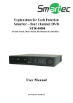
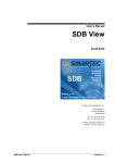
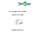
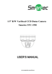
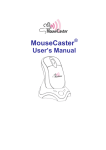
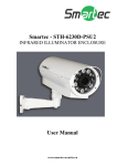
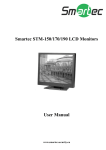
Explanation for Each Function
Smartec – eight and sixteen channel
DVR
STR-0884 /1684
(Front Panel, Rear Panel, IR Remote Controller)
User Manual
www.smartec-security.eu
1. Front Panel
The buttons on both the front panel of the DVR and IR Remote Controller have the same function, but may be different
each other in shape.
No.
Buttons
1
2
3
4
5
6
7
8
9
10
11
12
13
14
15
DVD Burner
DVD Burner Eject Button
Numeric Button
Power Button
Emergency Recording
USB Port
IR Sensor Window
Direction Button
Enter Button
Menu Button
Search Button
Screen Mode/Display Button
Return Button
Play/Pause Button
PTZ/Focus Button
16
LED Indicator
17
Jog/Shuttle Knob
Functions
Backup the recorded image by internal DVD burner (Option)
Eject DVD trash
Select the desired channel or input password
System startup or shutdown
Instant recording for all channels at CIF resolution up to maximum fps rate
USB port (Ver 2.0) for mouse operation or Image backup
Sensor Input for IR remote controller
Move to the desired menu position
Select value or setting and quick backup function during playback
Open system menu
Go to search mode
Select screen display mode or rotation mode
Cancel setup or return to previous mode
Play or pause by toggle during playback
Control camera PTZ and focus
Indicates system status
Power, Record and Network status
Image playback in various speed or frame by frame
Note
Emergency Recording (Instant Recording)
DVR will instantly start recording for all channels at CIF resolution up to maximum fps rate in total when user
presses the “REC” button. All channels, regardless of recording mode & recording on/off, are to be recorded.
Note
Emergency Backup (Quick Backup)
In playback mode, user can press “ENTER” button to set backup “start” time. Once “Quick backup starts” message
is shown, and then press the same “ENTER” button again to set backup “end” time. Then backup menu window
will be popped up to save the selected video images.
1.1.1. DVD Burner (Option)
To install DVD Burner to backup the recorded image. Refer to “Setting > Backup” for detailed explanation.
1.1.2. IR Sensor Window (Remote Controller Receiver)
To receive input signal from the IR remote controller
1.1.3. USB Port (Version 2.0)
1) To backup recorded images by using USB storage device (USB Memory Stick or USB HDD).
2) System software upgrade
3) Mouse connection for system operation
1.1.4. Screen Mode/Display Button
Screen display mode can be selected.
1.1.5. PTZ Button
1) Once pressed, DVR is changed to Pan & Tilt mode.
User can control Pan & Tilt operation by using Direction Button
2) If pressed again, DVR is changed to Zoom & Focus mode
User can control Zoom & Focus operation by using Direction Button
1.1.6. Search Button
To search the recorded image by date and time.
Refer to “Operation > Search recording Image” for detailed image searching method.
1.1.7. Menu Button
To set the system configuration according to user requirement.
1.1.8. Direction Button
1) Live Display & Playback Mode
User can change channel no by using Left & Right arrow button.
User can change display mode by using Up & Down arrow button
2) Menu Mode (when system menu is displayed)
To move to desired menu position.
3) Pan & Tilt Mode (once PTZ Button is pressed)
To move connected camera to desired direction.
4) Zoom & Focus Mode (when PTZ Button is pressed again)
User can control Zoom-In & Out by using Up & Down arrow button.
User can control Focus-In & Out by using Left & Right arrow button
1.1.9. Return Button
To cancel the setting or return to previous mode.
1.1.10. Enter Button
1) To select value or setting
2) Quick backup function during playback. Refer to User Manual section 3.5
1.1.11. Shuttle
Jog/Shuttle dial is used to playback the recorded images. The inner dial is called Jog and the outer dial is called Shuttle.
The Jog/Shuttle dial has two kinds of functions. The Shuttle is used to speed up the playback speed of images by
clockwise or anti-clockwise. Playback speed is indicated as x2, x4, x8, x16, x32 on the lower end of the screen.
1.1.12. Jog
The Jog is used to find the recorded image frame by frame. Turn the Jog dial clockwise or anti-clockwise to see the image
frame by frame during pause state.
2. Rear Panel
[ 8 Ch DVR – 200/240 fps Recording Model ]
[ 16 Ch DVR – 200/240 fps Recording Model ]
No.
1
2
3
4
5
6
7
8
9
10
11
12
13
14
15
16
Name
Video-In
Video Loop-Out
Audio-In
Audio-Out
Video-Out
S-Video
Spot-Out
VGA-Out
USB Port
LAN Port
NTSC/PAL Selection
RS-485 Port
Sensor Input
Alarm Output
Power Input
Grounding Terminal
Description
Connect camera. (Supports NTSC/PAL)
Loop-out of camera images
Connect the audio input device (with amplifier)
Connect the audio output device (with amplifier)
Connect the CCTV monitor
Connect to S-Video terminal
Connect the spot monitor
Connect the P/C(VGA) monitor
USB port (Ver 2.0) for mouse operation or Image backup
10/100 Ethernet connection terminal
Select the video signal type
Connect the PTZ camera and/or external keyboard controller
Connect the external sensor
Connect the external alarm device
Power cable connection (Default : 12 V, 5~8A)
For device grounding
2.1.1. Video-In
To connect the camera input to the corresponding channel marked on rear panel.
Note
Camera Input voltage level is 1Vp-p±10%.
2.1.2. Loop-Out
To use the camera input to other device.
Without additional video distributor, camera image can be provided to other device.
2.1.3. Video-Out
To connect the CCTV monitor.
2.1.4. Spot-Out
The spot monitor can be used to display input images in automatic switching mode.
2.1.5. Audio-Out
To connect audio output device
Note
Use of audio output device with an amplifier is recommended
2.1.6. S-Video
One additional main monitor can be installed by using the S-Video output.
2.1.7. VGA-Out
To connect the P/C monitor.
2.1.8. NTSC / PAL Selection
Turn off the power of DVR and select the NTSC/PAL switch correctly. Then turn on the power again.
2.1.9. Audio-In
To connect audio input device.
2.1.10. USB Port (Version 2.0)
1) To backup recorded images by using USB storage device (USB Memory Stick or USB HDD).
2) System software upgrade
3) Mouse connection for system operation
2.1.11. LAN Port
To connect RJ-45 jack of LAN cable. Consult network administrator for proper network configuration.
2.1.12. Power Input
Before connecting the power cord to the system, check if the power is in accordance with the system specification.
2.1.13. Grounding Terminal
It is recommended for user to make grounding to protect the system against external electrical surge.
2.1.14. Terminal Block
1) Connect sensors (dry contact type) with each ground (GND) line to “G” pin.
2) Connect various alarm devices controlled by relay output.
3) Connect RS-485 cable for the control of PTZ camera and/or external keyboard controller
Note
Support both N/O (Normal Open) and N/C (Normal Close) types of sensor. If connected sensor is not
functioning, ensure wiring is correct. The connection method may differ according to the type of P/T/Z controller.
Enquire to your vendor for guidance.
1
2
3
4
5
6
15 16 17 18 19 20
7 8
9 10
11 12 13 14
21 22 23 24 25 26 27 28
No.
Sensor
No.
Alarm
No.
PTZ
2
3
4
5
6
7
8
9
10
16
17
18
19
20
21
22
23
24
Sensor 1
Sensor 2
Sensor 3
Sensor 4
Sensor 5
Sensor 6
Sensor 7
Sensor 8
Sensor Ground (1~8)
Sensor 9
Sensor 10
Sensor 11
Sensor 12
Sensor 13
Sensor 14
Sensor 15
Sensor 16
Sensor Ground (9~16)
11
12
13
14
25
26
27
28
Alarm 1 (+)
Alarm 2 (+)
Alarm 3 (+)
Alarm 4 (+)
Alarm 1 (-)
Alarm 2 (-)
Alarm 3 (-)
Alarm 4 (-)
1
15
RS 485 D+
RS 485 D-
8 sensor-inputs for 8 Ch DVR (Pin # 16~24 : Disabled)
3. IR Remote Controller
The function buttons of the IR Remote Controller are as below.
No.
1
2
3
4
5
7
6
8
9
10
11
12
13
14
15
16
1
2
3
4
5
6
7
8
9
10
11
12
13
14
15
16
17
18
Functions
Power Button
ID Selection Button
Numeric Button
PTZ Button
Preset Button on PTZ Mode
Focus Button on PTZ Mode
Zoom (In & out) Button on PTZ Mode
Preset Tour Button on PTZ Mode
Direction Button (Left/Right/Up/Down)
Enter (Selection) Button
Menu Button
Return Button
Playback Button on Search Mode
(Fast Backward/Playback/Stop/Fast Forward)
Search Button
Instant (Emergency) Recording Button
Auto-Sequence Button on Live Display Mode
Screen Mode Button
Backup Button
17
18
Note
To use the IR Remote Controller, set the initial ID to be same as the ID in the DVR in the menu of ;
SYSTEM > SYSTEM INFO > REMOTE ID. (Default ID # for DVR and IR Remote Controller is “0”)
All DVR(s) have same default ID when it is out from the factory. Therefore, when the default value is used, one
IR Remote Controller can control several DVR(s) at once. To prevent this, it is recommended to set different ID
between DVR and IR Remote Controller.
Procedure
How to setup the ID in IR Remote Controller
1) Keep pressing ID selection button marked as “#” for about 5 seconds.
2) Set the ID number by pressing numeric button on IR Remote Controller.
- ID number is available from 000 up to 255.
- You have to press numeric button as three-digit number format.
- For example, press “000” for 0, “023” for 23, “234” for 234.