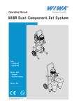
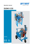
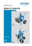
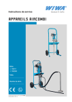
1
Operation Manual INTERNAL PIPE COATING SYSTEM Image shows a possible design variant Serial number ⸏⸏⸏⸏⸏⸏⸏⸏ Translation of the original operation manual Rohrinnenbeschichtung_BA_en_1312 · jw Declaration of Installation in accordance with Appendix II No. 1 B of the Machine Directive 2006 / 42 / EC, as amended by 2009 / 127 / EC WIWA Wilhelm Wagner GmbH & Co. KG Gewerbestr. 1-3 35633 Lahnau Germany hereby declares that the machine of type INTERNAL PIPE COATING SYSTEM with serial number ____________________ are incomplete machines according to Article 2g and designed exclusively for installation or assembly with another machine or item of equipment. These devices meet the following underlying safety and health and safety requirements from the above guideline: 1.1.2, 1.1.3, 1.1.5, 1.1.6, 1.2.1, 1.2.2, 1.2.3, 1.2.4.1, 1.2.4.3, 1.3.2, 1.3.4, 1.5.3, 1.6.3, 1.7.4.1, 1.7.4.2 Commissioning of the incomplete machine is prohibited until it has been established that the end product into which this machine is to be installed corresponds to the conditions of the EC Machinery Directive (2006/42/EC). The special technical documents are prepared in accordance with Appendix VII Part B of this guideline. Responsible for documentation: WIWA GmbH, Tel. +49 6441 609 0 The manufacturer undertakes to send by electronic means the special documents for the incomplete machine to single-nation bodies upon request. Lahnau, 25.03.2014 Place, Date 2 Heidrun Wagner-Turczak Managerial Associate Translation of the original operation manual Rohrinnenbeschichtung_BA_en_1312 • jw Contents Contents 1 Foreword......................................................................................................5 2 Safety...........................................................................................................6 2.1 Explanation of symbols.............................................................................6 2.2 Safety notes..............................................................................................8 2.2.1 Operating pressure.........................................................................8 2.2.2 Hazard from rotating parts..............................................................8 2.2.3 Hazard from electrostatic charging.................................................9 2.2.4 Explosion protection.......................................................................9 2.2.5 Health risks...................................................................................10 2.3 Safety features........................................................................................ 11 2.3.1 Compressed air shut-off valve...................................................... 11 2.3.2 Spray gun lock.............................................................................. 11 2.4 Operating and maintenance personnel...................................................12 2.4.1 Machine owner's duties................................................................12 2.4.2 Personnel qualification..................................................................12 2.4.3 Authorized operating personnel....................................................12 2.4.4 Personal protective equipment.....................................................12 2.5 Notes on warranty...................................................................................13 2.5.1 Conversions and alterations.........................................................13 2.5.2 Spare parts...................................................................................13 2.5.3 Accessories...................................................................................13 2.6 Emergency procedures...........................................................................14 2.6.1 Shutting down and depressurising the machine...........................14 2.6.2 Leakages......................................................................................14 2.6.3 Injuries..........................................................................................14 3 Machine Description..................................................................................15 3.1 Intended use...........................................................................................15 3.2 Functional description.............................................................................15 3.3 Machine design.......................................................................................16 3.3.1 Mounting kit..................................................................................17 3.3.2 Lance with motor..........................................................................18 3.3.3 Pipe guide.....................................................................................19 3.3.4 Rotary atomizer............................................................................20 3.3.5 Automatic spray gun.....................................................................20 4 Transport, installation and assembly.........................................................21 4.1 Transportation.........................................................................................21 4.2 Installation location.................................................................................21 Translation of the original operation manual Rohrinnenbeschichtung_BA_en_1312 • jw 3 Contents 4.3 Assembly................................................................................................22 4.3.1 Installing the mounting kit.............................................................22 4.3.2 Connecting the automatic spray gun............................................23 4.3.3 Connecting a lance with a hand-held spray gun...........................24 4.3.4 Reducing the holder to the pipe diameter.....................................24 5 Operation...................................................................................................25 5.1 Commissioning the machine...................................................................25 5.2 Coating...................................................................................................26 5.2.1 Hints for achieving good coating results.......................................27 5.3 Flushing..................................................................................................27 5.4 Material changes, work interruptions and decommissioning..................28 5.5 Disposal..................................................................................................29 6 Maintenance..............................................................................................30 6.1 Maintenance plan...................................................................................30 6.2 Checking, cleaning, adjusting the filter regulator....................................31 6.2.1 Adjusting the automatic condensate draining...............................31 6.2.2 Draining condensate manually.....................................................31 6.3 Cleaning the nozzle and the edge-type filter..........................................32 6.4 Supplied tools.........................................................................................32 7 Rectification of faults..................................................................................33 4 Translation of the original operation manual Rohrinnenbeschichtung_BA_en_1312 • jw Foreword 1 Foreword Dear Customer! We are delighted that you have decided in favour of a machine made by our company. This operating manual is intended for the operating and maintenance personnel. It contains all the information required to working with this machine. The owner of the machine must ensure that operators and maintenance personnel always have an operating manual at their disposal in a language that they understand! Safe and reliable operation of the machine requires further information in addition to this operating manual. You should have read and understood the guidelines and accident prevention regulations that apply in your country. In Germany, these are as follows: ➤➤ ZH 1/406 “Richtlinien für Flüssigkeitsstrahler” (Guidelines for Liquid Jets), published by the German “Hauptverband der Gewerblichen Berufsgenossenschaften”; ➤➤ BGR 500, chapter 2.29 “Application of Coating Materials”; ➤➤ BGR 500, chapter 2.36 “Working with Fluid Spraying Equipment” published by the employers liability insurance association for the gas, remote heating and water management sectors. We strongly recommend adding all relevant guidelines and accident prevention instructions to this operating manual. Moreover the manufacturer's instructions and guidelines for coating or feeder materials must be respected at all times. However, if you have any questions, please do not hesitate to contact us. Best wishes for good results with your machine from WIWA Wilhelm Wagner GmbH & Co. KG Copyright © 2013 WIWA This operating manual remains the copyright of WIWA Wilhelm Wagner GmbH & Co. KG. Gewerbestr. 1-3 • 35633 Lahnau • Germany Tel.: +49 6441 609-0 • Fax.: +49 6441 609-50 • E-mail: [email protected] • Internet: www.wiwa.de This operating manual is solely intended for personnel involved in preparation, operation and servicing. It is prohibited to pass on this operating manual for reproduction, utilisation or communication of its contents, unless this has been explicitly permitted. Non-compliance may result in claims for damage compensation. All rights reserved in the event of registration of the patented design, industrial design or registered design. This operating manual only applies in conjunction with the machine card that was given to you with the user manual for your equipment. Please check that the data on the type plate match those on the machine card. Please notify us immediately if there are discrepancies, if the user manual has been incorrectly compiled or if the type plate is missing. Translation of the original operation manual Rohrinnenbeschichtung_BA_en_1312 • jw 5 Safety 2 Safety This machine has been designed and manufactured under due consideration of all safety-related aspects. It complies with the current standard of technology and the valid accident prevention instructions. The machine left the factory in perfect condition and guarantees a high level of technical reliability and safety. Nevertheless, there are certain risks that can arise from incorrect operation or misuse: ➤➤ to life and limb of the operator or third party, ➤➤ to the machine and other material assets of the owner, ➤➤ to the efficient working capacity of the machine. You must refrain from any working methods that could affect the safety of operating personnel and equipment. All the people that are involved in set-up, commissioning, operation, maintenance, repair and servicing of the spray gun must have read and understood the operating manual beforehand, especially the chapter entitled “Safety”. Your safety is at stake! We recommend to the owner of this unit to have this confirmed in writing. 2.1 Explanation of symbols Safety information warns you of potential risks of accidents and tell you the measures that are needed to prevent accidents. In WIWA operating manuals, safety information is specially highlighted and marked as follows: DANGER Indicates danger of accidents; if you ignore the safety notes, there is a high risk of severe injury resulting up to and including death! WARNING Indicates danger of accidents; if you ignore the safety notes, severe injury can result up to and including death! CAUTION Indicates danger of accidents; if you ignore the safety notes, severe injury can result! Indicates important information on correct use of the machine. Ignoring it can result in damage to the machine or in its vicinity. 6 Translation of the original operation manual Rohrinnenbeschichtung_BA_en_1312 • jw Safety In the safety notes about the risk of accidents, different pictograms are shown after each hazard source - examples: General accident risk Risk of explosion from explosive atmosphere Risk of explosion from explosive substances Danger of injury due to electric voltage or electrostatic charging Risk of crushing by moving machine parts Risk of burning due to hot surfaces Mandatory safety instructions concern protective gear to be worn in the first instance. They are particularly highlighted and marked as follows: Wear protective clothing Highlights the order to wear the prescribed protective clothing to protect against skin injuries caused by spraying material or gases. Use eye protection Indicates the requirement to wear protective goggles to protect against eye injuries caused by gases, fumes or dust. Wear ear defenders Indicates the requirement to wear ear defenders to prevent your hearing from being damaged by noise. Use a respiratory protection mask Highlights the order to use a respiratory protection mask to prevent your respiratory tract from being damaged by gases, fumes or dusts. Wear protective gloves Highlights the order to wear protective gloves with lower arm protection to protect against burn injuries caused by heated materials. Wear protective footwear Highlights the order to wear protective footwear to prevent injuries to the feet due to objects that may fall, drop or roll around or to hot or caustic liquids. Indicates references to guidelines, work instructions and operating manuals that contain important information which you must observe at all times. Translation of the original operation manual Rohrinnenbeschichtung_BA_en_1312 • jw 7 Safety 2.2 Safety notes Please remember that the machine works at high pressure and with very high speeds and may cause life-threatening injuries if used inappropriately! Observe and follow all information in this operating manual and in the operating manual of the spraying device used at all times. The accident prevention instructions “Application of Coating Materials” (BGR 500, chap. 2.29) and the guidelines for liquid jets ZH1/406 of the employer's liability insurance association must strictly be complied with. 2.2.1 Operating pressure WARNING Components that do not comply with the maximum permissible operating pressure can burst and cause serious injury. ➤➤ The specified maximum operating pressures must generally be complied with for all components. In case of varying operating pressures, the lowest value is always the one to be taken as the maximum operating pressure for the entire machine. ➤➤ Material hoses and hose assemblies must comply with the maximum working pressure, including the required safety factor. ➤➤ Material hoses must be leak tight and free of kinks, signs of abrasion or bulges. ➤➤ Hose connections must be tight. 2.2.2 Hazard from rotating parts WARNING Clothing, long hair, scarves and other items may become entangled in the rotating rotary atomizer. This can result in crushing or strangulation. ➤➤ Only operate the rotary atomizer inside a pipe! ➤➤ Wear the required work clothing. ➤➤ Tie back long hair. ➤➤ Do not wear scarves or baggy clothing. CAUTION The rotary atomizer reaches very high speeds. This may cause injuries from touching the rotary atomizer and/or from ejected materials. ➤➤ Only operate the rotary atomizer inside a pipe! ➤➤ Switch off the rotary atomizer before removing the lance from the pipe. ➤➤ Never stop the rotary atomizer by hand or with another body part! ➤➤ Never touch the rotating rotary atomizer! 8 Translation of the original operation manual Rohrinnenbeschichtung_BA_en_1312 • jw Safety 2.2.3 Hazard from electrostatic charging WARNING The high speeds of the rotary atomizer may cause electrostatic charging. Static discharges can cause fire and explosion. ➤➤ Ensure that the spraying device and the object to be coated are earthed correctly! ➤➤ Always use open containers! Never spray inside cone-top cans or drums with bungholes! ➤➤ Never operate the rotary atomizer with solvent or materials containing solvents! ➤➤ Place the containers on a grounded surface. ➤➤ Always use electrically conductive containers. ➤➤ Avoid contact between spray gun and container wall. ➤➤ Use only electrically conductive material hoses. All original material hoses from WIWA are conductive and perfectly adapted to our equipment. 2.2.4 Explosion protection WARNING Machines that are designed without explosion protection must not be used in workshops that are subject to the explosion protection ordinance. Whether your machine has explosion protection is indicated by the symbol on the type plate and/or on the enclosed ATEX declaration of conformity. Explosion-protected machines meet the explosion protection requirements of Directive 94/9/EC for the explosion group, unit category and temperature class specified on the type plate or in the declaration of conformity. The operator is responsible for determining the zone allocation according to the Directive of EC 94/9/EC, Appendix II, no. 2.1-2.3 when observing the measures of the responsible inspecting authority. The operator is responsible for checking and ensuring that all technical data and markings according to ATEX correspond with the necessary requirements. Please note that several components have their own type plate with separate marking according to ATEX. In this case the lowest explosion protection of all attached markings applies for the entire machine. Applications where the malfunction of the unit can lead to danger to personnel must be provided with respective safety measures by the operator. However, if agitators, heaters or other electrically accessories are additionally mounted, one must check the explosion protection. Plugs for heaters, agitators, etc. that do not have explosion protection, may only be plugged in outside of areas that fall under the explosion protection ordinance, even if the accessory equipment as such is explosion protected. Translation of the original operation manual Rohrinnenbeschichtung_BA_en_1312 • jw 9 Safety WARNING Heating up cleaning agents can cause an explosion. This may result in serious injury to persons and damage to property. ➤➤ Pay attention to the flashpoint and the ignition temperature of the cleaning agent. ➤➤ Switch off the material flow heater if you need to perform the following work: Cleaning, pressure testing, decommissioning, maintenance and repair. 2.2.5 Health risks Follow the safety notes and dosing information of the manufacturer and the generally applicable regulations when handling paints, cleaning agents, oils, greases and other chemical substances. CAUTION Depending on the materials being applied, solvent vapours may result that can cause damage to health and property. ➤➤ Always ensure sufficient aeration and ventilation at the workplace. ➤➤ Always observe the processing instructions issued by the material manufacturers. When cleaning your skin, use only appropriate skin protection, skin cleaning and skin care products. In closed or pressurized systems dangerous chemical reactions may occur if parts made of aluminium or galvanized parts come into contact with 1.1.1 trichloroethane, methylene chloride or other solvents containing halogenated hydrocarbons (CFC's). If you want to process materials containing the afore mentioned substances, we recommend to consult the material manufacturer to clarify the usability of such substances. For these materials, we have available a range of rust- and acid-proof machines. 10 Translation of the original operation manual Rohrinnenbeschichtung_BA_en_1312 • jw Safety 2.3 Safety features WARNING If one of the safety features is missing or not fully functional, the operating safety of the machine cannot be guaranteed! ➤➤ If you discover any faults in the safety features or other deficiencies on the machine, stop operation of the machine immediately. ➤➤ Only resume operation of the machine after the fault has been completely eliminated. Safety features must be checked with the machine depressurised: ➤➤ before initial commissioning, ➤➤ always before starting work, ➤➤ after set-up work, ➤➤ after all cleaning, servicing and repair work. The machine is equipped with the following safety features: ➤➤ Spray gun lock (only for hand-held spray gun) ➤➤ Compressed air shut-off valve Check list: 55 Check correct function of spray gun lock 55 Check correct function/operability of compressed air shut-off valve 55 Also check the correct function of the safety features on the spraying device used in line with the operating manual. 2.3.1 Compressed air shut-off valve The compressed air shut-off valve interrupts the air supply to the rotary atomizer motor. Principle of function: ➤➤ Open in the direction of flow ➤➤ Close across the direction of flow 2.3.2 Spray gun lock Hand-held spray guns are equipped with a safety lever for locking the trigger. The spray gun must always be secured against unintended operation, even for the shortest of work breaks. Set the safety lever horizontally to secure the spray gun. Fig. 1: Spray gun lock Translation of the original operation manual Rohrinnenbeschichtung_BA_en_1312 • jw 11 Safety 2.4 Operating and maintenance personnel 2.4.1 Machine owner's duties The machine owner: ➤➤ is responsible for the training of the operating and maintenance staff, ➤➤ must instruct the operating and maintenance staff in correct handling of the machine as well as in wearing the correct work clothing and personal protective equipment, ➤➤ must make the user manual available to the operating and maintenance staff and ensure that it always remains available, ➤➤ must ensure that the operating and maintenance staff have read and understood the user manual. Only then may the machine be brought into service. 2.4.2 Personnel qualification A differentiation is made between two groups of people in dependence on their qualifications: ➤➤ Instructed operators have been verifiably instructed by the machine owner in the activities they are tasked with and the potential risks connected with them in the case of incorrect behaviour. ➤➤ Trained personnel have been instructed by the machine builder such that they are capable of carrying out maintenance and repair work on the system and recognising potential risks on their own initiative and of avoiding these risks. 2.4.3 Authorized operating personnel Activity Qualification Set-up and operation Instructed operator Cleaning Instructed operator Servicing Trained personnel Repair Trained personnel Young persons under the age of 16 are not allowed to operate this machine. 2.4.4 Personal protective equipment Wear protective clothing Always wear the protective clothing prescribed for your work environment (mining, closed rooms, etc.) and also follow the recommendations in the safety data sheet issued by the material manufacturer. Use eye protection Wear protective goggles to protect against eye injuries caused by material splatter, gases, fumes or dust. 12 Translation of the original operation manual Rohrinnenbeschichtung_BA_en_1312 • jw Safety Wear ear defenders Operating personnel should be provided with suitable noise protection equipment. The machine operator is responsible for adhering to the accident prevention regulation “Noise” (BGV B3). For this reason, pay special attention to the conditions at the installation location – the noise burden, for example, will increase if the system is installed in or on hollow bodies. Wear a respiratory protection mask We strongly recommend that you wear a respiratory protection mask, even though the paint mist has been minimized in the airless spray painting method given a correct pressure setting and correct working methods. Wear protective gloves When applying heated materials you should wear protective gloves with lower arm protection, to protect you against burn injuries. Wear protective footwear Wear protective footwear to prevent injuries to the feet due to objects that may fall, drop or roll around and to prevent slipping on a slippery floor. 2.5 Notes on warranty 2.5.1 Conversions and alterations ➤➤ Unauthorized conversions or alterations should not be undertaken on safety grounds. ➤➤ Protective equipment should not be dismantled, converted or bypassed. ➤➤ The machine must only be operated within the specified limiting values and machine parameters. 2.5.2 Spare parts ➤➤ When carrying out maintenance and repair work, you must only use WIWA original spare parts. ➤➤ Use of components which have not been manufactured or delivered by WIWA renders any warranty null and void. 2.5.3 Accessories ➤➤ Using original WIWA accessories guarantees that they are usable in our machines. ➤➤ If you use third-party accessories, they must be suitable for the machine – particularly with regard to the operating pressure, the electrical connection data and the connection sizes. WIWA accepts no liability for damage or injuries resulting from the use of these parts. ➤➤ You must observe the safety regulations of the accessories. These safety regulations are found in the separate operating instructions for the accessories. Translation of the original operation manual Rohrinnenbeschichtung_BA_en_1312 • jw 13 Safety 2.6 Emergency procedures 2.6.1 Shutting down and depressurising the machine In an emergency, immediately shut down the machine and depressurise it. 1. Close the compressed air shut-off valves for the rotary atomizer motor and the spraying device. 2. Open the ball valve on the high pressure filter of the spraying device. 3. Operate the spray gun again briefly to relieve any residual material pressure, ensuring full pressure release for the machine. CAUTION The machine has not been flushed. The material in the machine can harden and clog it up. ➤➤ This procedure is not suitable for decommissioning. ➤➤ After remedying the emergency, the machine has to be flushed (see “5.3 Flushing” on page 27). Pay attention to the potlife of the material used. Observe the operating manual for the spraying device used. 2.6.2 Leakages WARNING In case of leakages material can escape under very high pressure and cause serious bodily injuries and material damage. ➤➤ Immediately shut down the machine and depressurise it. ➤➤ Re-tighten any screw fittings and replace defective components (only by trained personnel). ➤➤ Do not try to seal leaks on the connections and high-pressure hoses with the hand or by wrapping fabric around them. ➤➤ Do not repair material hoses! ➤➤ Before recommissioning the machine, check the hoses and screw fittings for leaks. 2.6.3 Injuries If injured by processing materials or cleaning agents, always have available the safety data sheet (address, phone number, material designation and material number of the supplier or manufacturer) for the attending physician. 14 Translation of the original operation manual Rohrinnenbeschichtung_BA_en_1312 • jw Machine Description 3 Machine Description Internal pipe coating is required in many areas of technology to protect pipes, hollow bodies and profiles against corrosion and other harmful influences. This device can be used to apply one-component and two-component coatings without rotating the pipe. The technical data for your machine can be found in the attached machine card. 3.1 Intended use This device is used for applying internal coatings to pipes etc. The device is intended for assembly with an airless spraying device (one or two components). The internal pipe coating system can be used with automatic or hand-held spray guns on spray lances with pipe guides for different diameters. This also allows internal coating of installed pipes using robot technology and an rotary atomizer. Any other use is considered to be unintended. If you intend to use the machine for other purposes or with other materials and thus not for the purpose for which it is intended, you must ask WIWA for permission – otherwise the warranty will be invalidated. Intended use also includes compliance with the technical documentation and adherence to the prescribed operating, servicing and maintenance guidelines. 3.2 Functional description The internal pipe coating system is pulled centrally through the inside of the pipe using an automatic feeding unit (not provided by WIWA) or a mechanical guide. Supply lines connect the internal pipe coating system to the spraying device or the mixing unit as well as to the compressed air supply. An rotary atomizer is located in front of the material outlet. It is driven by a separate air motor and reaches very high speeds. The rotary atomizer ejects the emitted coating material almost vertically onto the inner wall of the pipe to achieve an even coating. Translation of the original operation manual Rohrinnenbeschichtung_BA_en_1312 • jw 15 Machine Description 3.3 Machine design Depending on the system design, the internal pipe coating system consists of several components such as: ➤➤ Lance with pneumatically driven motor for the rotary atomizer and supply lines for air and spraying material ➤➤ Pipe guide or holder (optional) ➤➤ Rotary atomizer ➤➤ Spray gun: automatic or hand-held ➤➤ Mounting kit with compressed air shut-off valve, air pressure regulator, pressure gauge, ON/OFF switch for the spray gun and air maintenance unit, if required 2 1 5 4 3 Fig. 2 Sample system structure in combination with a one-component spraying device No. Designation 1 Spray gun 3 ON/OFF switch for the spray gun 2 4 5 Mounting kit with filter regulator and pressure gauge Spray gun (shown here: automatic) Lance with guide and rotary atomizer 1 Fig. 3 16 2 3 4 Machine structure with hand-held lance Translation of the original operation manual Rohrinnenbeschichtung_BA_en_1312 • jw Machine Description No. Designation 1 Rotary atomizer (with different diameters) 3 Lance (in different lengths) 2 4 Guide (for different pipe diameters) Spray gun (automatic or hand-held) 3.3.1 Mounting kit 1 2 3 4 5 8 7 6 Fig. 4 Mounting kit 0655044 No. Designation 1 2 3 4 5 6 7 8 Translation of the original operation manual Rohrinnenbeschichtung_BA_en_1312 • jw Connection to a pressure outlet (e.g. on the air maintenance unit of the spraying device) Air pressure regulator Setting can be fixed by pressing down the regulator Pressure gauge for displaying the air inlet pressure for the rotary atomizer motor Air for driving the rotary atomizer motor inside the lance ON/OFF switch for the automatic spray gun Control air for the automatic spray gun Filter with semi-automatic outlet Compressed air shut-off valve 17 Machine Description 3.3.2 Lance with motor 1 2 3 4 5 Fig. 5 1 6 0656960 - lance for automatic spray gun 2 3 4 6 7 Fig. 6 5 0656948 - hand lance (shown shortened) with hand-held spray gun No. Designation 1 Material outlet in the rotary atomizer 3 Material line (on the outside of the lance) 2 4 5 6 7 Motor for rotary atomizer Air line (inside the lance) Material inlet Air inlet Compressed air shut-off valve (rotary atomizer ON/OFF) Pay attention to the operating manual for the spray gun used. 18 Translation of the original operation manual Rohrinnenbeschichtung_BA_en_1312 • jw Machine Description 3.3.3 Pipe guide Fig. 7 Guide with adjustable arms The guides (see Fig. 7) are available in different versions to cover diameters between 80- 800 mm. The design and the operating principle are the same for all guides. The arms of the guides are adjustable and can be set continuously to the required pipe diameter. The setting is fixed by tightening the screws. Guide (see Fig. 7) Article no. Ø 80 - 400 0656954 (steel) Ø 400 - 800 0656956 0656949 (aluminium) For pipe diameters below 80 mm, small holders with rollers are used instead of a guide. Fig. 8 Holder with rollers Fig. 9 Holder without rollers The holders with rollers (see Fig. 8) are not adjustable. The rollers can be made smaller to adjust the holders to the desired pipe diameter (“4.3.4 Reducing the holder to the pipe diameter” on page 24). Holder with rollers (see Fig. 8) Article no. Ø 77.5 - 97 0657949 Ø 69 - 78.8 0657948 The holders without rollers (see Fig. 9) are used for pipe diameters below 70 mm. They are available in 3 sizes (Ø 50, Ø 60 and Ø 65). Translation of the original operation manual Rohrinnenbeschichtung_BA_en_1312 • jw 19 Machine Description Holder without rollers (see Fig. 9) Article no. Ø 60 0658051 Ø 50 Ø 65 0658050 0658052 3.3.4 Rotary atomizer The rotary atomizer is mounted in the collet chuck of the motor at the tip of the lance (recommended tightening torque 8 Nm). No. Designation 1 1 2 2 Elongated holes through which the material is ejected onto the surface Shaft Ø 8 mm for mounting in the collet chuck (M8) Fig. 10 Rotary atomizer Rotary atomizer (see Fig. 10) Article no. Ø 45 0656958 Ø 33 0656957 Ø 90 0656959 3.3.5 Automatic spray gun 1 No. Designation 1 2 2 3 4 3 4 5 6 Control air connection for closing the valve Control air connection for opening the valve Material inlet 3/8 NPSM (I ÜWM) Edge-type filter (internal, not shown) incl. M100 + M60 Nozzle (internal, not shown) incl. 053 / 40 + 068 /40 + 073 / 40 (other sizes on request) Material outlet 1/4 NPSM (A) 5 6 Fig. 11 Automatic spray gun 4 mm (0655976) 20 Translation of the original operation manual Rohrinnenbeschichtung_BA_en_1312 • jw Transport, installation and assembly 4 Transport, installation and assembly The machine left the factory in flawless condition and was appropriately packed for transportation. Check the machine on receipt for any damage in transit and for completeness. 4.1 Transportation Please follow these notes when transporting the machine: ➤➤ Fold up the guide tightly. ➤➤ Secure the load on the transport vehicle against slipping and falling off. If the machine had already been in operation, please observe the following: ➤➤ Disconnect the entire power and paint supply for the device – even for short transport distances. ➤➤ Empty the machine before transport – fluid residues may escape during transport despite this measure. ➤➤ Remove all loose components (e.g. tools) from the machine. ➤➤ Assemble the parts or fittings dismantled for transport purposes before start up and in compliance with the intended use of the system. 4.2 Installation location WARNING If the spraying device is used outside during a thunderstorm, a lightning strike can cause a life-threatening situation for the operating personnel. ➤➤ Do not operate the spraying device during a thunderstorm! ➤➤ The machine owner has to ensure that the spraying device is equipped with suitable lightning protection. Safety measures at the place of installation: ➤➤ Always keep the working area, especially all walkways and standing areas, clean and tidy. Immediately remove any spilled material and cleaning agent. ➤➤ Always ensure adequate ventilation at the work place to avoid damage to health and material objects. ➤➤ Always observe the processing instructions issued by the material manufacturers. ➤➤ Even though there are no legal regulations, all hazardous cleaning agent vapours and paint particles should be extracted. ➤➤ Protect objects adjacent to the spraying object against possible damage caused by the material mist. Translation of the original operation manual Rohrinnenbeschichtung_BA_en_1312 • jw 21 Transport, installation and assembly 4.3 Assembly WARNING If assembly work is carried out by people who have not been trained for this work, you endanger yourself and other people and impair the safety and reliability of the machine. ➤➤ Electrical components must only be mounted by trained time-served electricians – with all the other components, e.g. the spray hose and the spray gun being assembled by trained personnel only. 4.3.1 Installing the mounting kit WARNING Components that do not comply with the maximum permitted operating pressure of the machine can burst and cause serious injury. ➤➤ Check the maximum permitted operating pressure of the material hose and the spray gun before assembly. It must be greater than or equal to the maximum operating pressure of the machine as specified on the type plate. When using a hand-held lance, only a filter regulator (not included) has to be mounted before the compressed air shut-off valve (“4.3.3 Connecting a lance with a hand-held spray gun” on page 24. When using a lance with an automatic spray gun, a mounting kit has to be additionally installed. The mounting kit can be installed on the transport box of the pneumatic mixer using the mounting plates provided. To connect the mounting kit please see “Fig. 4 Mounting kit 0655044” on page 17. The compressor capacity must match the air requirements of the machine and the diameters of the air supply hoses must match the connections such that an adequate air supply is ensured. Operation with contaminated or moist compressed air causes damage to the machine's pneumatic system. ➤➤ Use only dry dust- and oil-free air! 22 Translation of the original operation manual Rohrinnenbeschichtung_BA_en_1312 • jw Transport, installation and assembly 4.3.2 Connecting the automatic spray gun 1. Create a compressed air connection between mounting kit and lance. The hose connectors for connecting the hoses are included in the delivery. The compressed air hoses are not part of the delivery. They are available from WIWA by the metre. 2. Connect the pneumatic hoses between the pneumatic valve on the “Gun ON/OFF” switch and the automatic spray gun. Control air (permanent) =1 Open =4 Close =2 5 4 1 2 3 Fig. 12 Connections to pneumatic valve (ON/OFF switch for automatic gun) 1 2 4 3 Fig. 13 Connecting the automatic spray gun No. Designation 1 Material hose from high-pressure filter or mixing unit 3 Pneumatic hose for closing the valve 2 4 Pneumatic hose for opening the valve Control air (permanent) from the mounting kit 3. Connect the material hose. For one-component systems connect the hose directly to the high-pressure filter of the spraying device. A mixer is interposed for two-component systems. Translation of the original operation manual Rohrinnenbeschichtung_BA_en_1312 • jw 23 Transport, installation and assembly 4.3.3 Connecting a lance with a hand-held spray gun A filter regulator has to be used for a lance with a hand-held spray gun. This filter removes condensate and contaminations from the supplied air and allows adjustment of the air inlet pressure for the rotary atomizer motor. This filter regulator has to be installed in the air hose before the compressed air shut-off valve of the lance. 1. Connect the compressed air supply (1). 2. Connect the material hose (2). 1 Fig. 14 Connecting material and air supply to the hand lance 2 4.3.4 Reducing the holder to the pipe diameter Guides cannot be used on pipe diameters below 80 mm as the guides are thicker. Holders with rollers are used instead. The holders with rollers are not adjustable. The rollers can be made smaller to adjust the holders to the desired pipe diameter. On request we can adapt the holders to the required pipe diameter according to your specifications. Fig. 15 Holder with rollers 1. Release the screws (1) in the roller axes and remove the roller. 2. Place the roller into a lathe and turn the roller until it has reached the desired size. 1 Please note that all rollers have to be turned the same, producing a triple reduction in the overall diameter of the holder. 3. Re-attach the rollers to the holder. Fig. 16Removing the roller 24 Translation of the original operation manual Rohrinnenbeschichtung_BA_en_1312 • jw Operation 5 Operation WARNING Explosion hazard! Processing solvents or materials containing solvents in connection with an rotary atomizer device can cause sparks and therefore explosions. This may result in serious injury to persons and damage to property. ➤➤ Do not use any solvents or materials containing solvents with the internal pipe coating system. Observe the technical notes of the respective material manufacturer. Observe the operating manual for the spraying device used. 5.1 Commissioning the machine Prerequisites for commissioning: ➤➤ The machine has to be fully assembled. ➤➤ Do not commission the machine unless you have the specified protective equipment. For details, refer to chapter 2.4.4 on page 12. ➤➤ A sufficient quantity of the spraying material has to be available. ➤➤ A sufficient quantity of a suitable cleaning agent has to be available for flushing the system parts filled with mixed material within the potlife. Observe the operating manual for the spraying device used. ➤➤ Check whether all safety features are installed and fully operational. ➤➤ Check the level of lubricant in the oil container of the air maintenance unit (if fitted) and top up if required. ➤➤ Flush the machine (see chapter 5.3 on page 27) to remove the factory test medium (for first operation) or any residue of previous spraying material. ➤➤ During commissioning (flushing), check whether all machine parts are tight and re-tighten the connections if required. ➤➤ Ensure correct grounding of the spraying device and of the object to be coated (see operating manual of the spraying device). Translation of the original operation manual Rohrinnenbeschichtung_BA_en_1312 • jw 25 Operation 5.2 Coating Before coating, carry out the steps for commissioning (see chapter see 5.1 Commissioning the machine). 1. Calculate the surface area to be coated (e.g. inside pipe area = 5 m2). 2. Calculate the required volume of material (e.g. layer thickness 2 mm × surface area 5 m2 = total volume 10 l). When calculating the total volume, take into account that certain materials release moisture during drying which decreases the thickness of the dried layer. Add these drying losses to the total volume. 3. Take into account the duration for the pipe coating process as this provides the flow volume per minute (e.g. 10 l in 4 min = 2.5 l/min). The time factor is often determined by the previous and/or subsequent steps. 4. Measure the material output conveyed by the system without rotary atomizer (!) in one minute. Run the system e.g. with 2 bar air inlet pressure while counting the double strokes of the pump during that time. If e.g. a flow volume of 2 l results after one minute and 13 double strokes, increasing the air inlet pressure to 2.5 bar (or approx. 16 double strokes) could already produce the desired result of 2.5 l/min. Repeat the test if necessary. 5. If the test without rotary atomizer was successful, you should carry out a test coating of a pipe with rotary atomizer. If steps 1 - 4 were carried out properly, the result of the test coating should already correspond to the target values. WARNING The rotary atomizer reaches very high speeds. This may cause injuries from touching the rotary atomizer and/or from ejected materials. ➤➤ Only operate the rotary atomizer inside a pipe! ➤➤ Switch off the rotary atomizer before removing the lance from the pipe. ➤➤ Never stop the rotary atomizer by hand or with another body part! ➤➤ Never touch the rotating rotary atomizer! Changes to certain parameters can have a crucial influence on the coating result, e.g.: ➤➤ Nozzle size (small nozzle less material output) ➤➤ Temperature (higher temperature decreases the viscosity more material output if the nozzle size allows) ➤➤ Pressure (higher air inlet pressure more material output if the nozzle size allows) ➤➤ Feed rate (slower) thicker layer) 26 Original operating manual Rohrinnenbeschichtung_BA_en_1312 • jw Operation 5.2.1 Hints for achieving good coating results ➤➤ To coat a pipe, insert the lance completely into the pipe and start at the other end of the pipe. The lance is pulled back through the pipe. That means that the pipe is coated behind the lance without touching or even damaging the applied coating. ➤➤ Ensure an even feed rate, particularly when using hand-held lances. ➤➤ Switch on the rotary atomizer before starting the material feed. That way, you will achieve perfect, soft and smooth overlapping of the spray jet and avoid excessively thick application of material at the beginning of the spraying process. ➤➤ Stop the material feed before switching off the rotary atomizer. ➤➤ Replace the spray nozzle before it is worn. Worn nozzles cause higher material consumption and therefore thicker layers of coating. 5.3 Flushing Flushing the machine is necessary: ➤➤ At initial commissioning The machine has to be flushed with a cleaning agent to ensure that the spraying material is not negatively affected by the test medium that was used at the factory to test correct functioning. ➤➤ When changing materials ➤➤ For work interruptions and at decommissioning in the case of an interruption in spraying to flush spraying material out before it sets. Take note of the potlife of the materials used, particularly when using twocomponent materials. Original operating manual Rohrinnenbeschichtung_BA_en_1312 • jw 27 Operation WARNING Explosion hazard! Processing solvents or materials containing solvents in connection with an rotary atomizer device can cause sparks and therefore explosions. This may result in serious injury to persons and damage to property. Therefore, follow these instructions during cleaning and while materials containing-solvent may be in the system: ➤➤ Always clean the rotary atomizer device outside of explosion-endangered environments (e.g. in well ventilated rooms or outdoors). ➤➤ Turn down the air pressure regulator on the rotary atomizer device completely and close the compressed air shut-off valve for the internal pipe coating. WARNING Heating up cleaning agents can cause an explosion. This may result in serious injury to persons and damage to property. ➤➤ Before flushing the machine, switch off the material flow heater (optional) and leave it to cool completely. ➤➤ You will need: •• at least 5 l of cleaning agent which suits the processed material and is recommended by the material manufacturer, in an open container •• an additional collecting vessel for the flushed out cleaning agent •• These containers are not included in the scope of delivery. 1. Dismount the rotary atomizer using the supplied tool. 2. Clean the rotary atomizer by hand using a suitable solvent. 3. Use the spraying device to flush a suitable cleaning agent through the lance instead of the spraying material. Observe the operating manual for the spraying device used. 5.4 Material changes, work interruptions and decommissioning Flush the machine within the potlife stated by the manufacturer of the spraying material. Observe the operating manual for the spraying device used. 28 Translation of the original operation manual Rohrinnenbeschichtung_BA_en_1312 • jw Operation 5.5 Disposal At the end of use, you must shut down and dismantle the machine and dispose of it in accordance with legal regulations. ➤➤ Clean the machine thoroughly of all material residues. ➤➤ Dismantle the machine and separate all materials – dispose of metal together with scrap metal; plastic parts can be disposed of as domestic waste. ➤➤ Rests of spraying material, cleaning agent, oils, greases and other chemical substances must be collected in accordance with statutory provisions concerning recycling and waste disposal. The official local waste water laws are valid. Translation of the original operation manual Rohrinnenbeschichtung_BA_en_1312 • jw 29 Maintenance 6 Maintenance WARNING If maintenance and repair work is carried out by persons who have not been trained for this work you endanger yourself, other persons and impair the safety and reliability of the machine. ➤➤ Maintenance and repair work on electrical components may only be carried out by trained electricians – any other maintenance and repair work has to be performed by WIWA customer service or by specially trained personnel. Before maintenance and repair work: 1. Switch off the spraying device. 1. Cut off the compressed air supply. 2. Ensure full pressure release on spraying device and internal pipe coating system. WARNING Despite releasing the pressure, material congestion or agglomeration of material may mean that there are residual pressures still present. These may suddenly release during disassembly work and can result in serious injuries. ➤➤ You must be particularly careful during disassembly work! ➤➤ When disconnecting material hoses you should cover the screw fitting with a cloth to catch any escaping material sprays. After completing maintenance and repair work, check the function of all the safety features and that the machine is functioning correctly. 6.1 Maintenance plan The information in the maintenance plan is a recommendation. The intervals may vary in dependence on the condition of materials used and outer influences. Interval Activity Reference daily clean nozzle and filter on the spray gun “6.3 Cleaning the nozzle and the edge-type filter” on page 32 before each start-up weekly check machine for external damage check and clean the filter regulator visually check the compressed air and material hoses for damage, bends and crushing 30 “6.2 Checking, cleaning, adjusting the filter regulator” on page 31 Translation of the original operation manual Rohrinnenbeschichtung_BA_en_1312 • jw Maintenance Interval Activity every three years inspection of the compressed air and material hoses by an expert and replacement if necessary after max. 1,000 operating hours check the fins of the rotary atomizer motor for wear and replace if necessary Reference This task may only be carried out by WIWA customer service or specially trained personnel. 6.2 Checking, cleaning, adjusting the filter regulator The filter regulator prevents condensation and dirt particles from entering the machine. Any condensate will collect in the storage container (1) and can be drained using a semi-automatic drain valve. Regularly check the storage container regularly for dirt residue and clean if necessary by removing the container. 6.2.1 Adjusting the automatic condensate draining 1. Turn the drain screw (2) out until it only just remains in the thread. The valve opens from a pressure of ≤ 1.5 bar (machines unpressurised). The residual pressure is enough to force the condensate out of the container. When pressure is applied again the valve closes at ≥ 1,5 bar. With this setting, condensate will only be drained when there is no pressure. For longer periods of operation, however, condensate may accumulate above the maximum filling level of the condenser and enter the compressed air system. Drain condensate manually, if necessary, to prevent this (“6.2.2 Draining condensate manually” on page 31). 1 2 Fig. 17 Filter regulator 6.2.2 Draining condensate manually 1. Turn the drain screw (2) in all the way so the condensate outlet is closed. 2. Turn the drain screw out until condensate is released. Manual condensate draining also works when the machine is under pressure. Automatic condensate draining does not work with this setting (“6.2.1 Adjusting the automatic condensate draining” on page 31). Translation of the original operation manual Rohrinnenbeschichtung_BA_en_1312 • jw 31 Maintenance 6.3 Cleaning the nozzle and the edge-type filter No. Designation 1 Housing for valve filter 3 Nozzle 2 4 5 Edge-type filter Seal Socket nipple 1. Unscrew the socket nipple (5) by countering the housing of the nozzle filter (1). 2. Remove the nozzle (3) and the edge-type filter (2) from the automatic gun. If necessary, push the parts out of the socket nipple from the front. 3. Place both parts in a suitable cleaning agent. 4. In case of damage or permanent soiling the parts have to be replaced. Also check the seal (4). 5. Re-insert all parts and tighten the socket nipple. 1 2 3 4 5 Fig. 18 Removing the nozzle and the edge-type filter 6.4 Supplied tools The following tools are included in the delivery: ➤➤ 2 open-end wrenches WAF 12 and WAF 17 for securing the rotary atomizer in the collet chuck of the motor 32 Translation of the original operation manual Rohrinnenbeschichtung_BA_en_1312 • jw Rectification of faults 7 Rectification of faults Fault Possible cause/s Remedy 1.) no material output ➤➤ gun OFF ➤➤ switch ON the gun ➤➤ spraying device OFF or not ➤➤ open compressed air supply for the spraying working device and adjust spraying pressure ➤➤ material hose bent ➤➤ nozzle/filter clogged ➤➤ material feed faulty 2.) not enough material output ➤➤ nozzle clogs up 3.) too much material output ➤➤ nozzle worn 4.) rotary atomizer rotates too slowly or not at all ➤➤ air inlet pressure for the rotary atomizer motor too low or non-existent ➤➤ feed rate too high ➤➤ feed rate too slow ➤➤ clean nozzle/filter, replace if worn or damaged ➤➤ Is there still enough spraying material? ➤➤ note the operating manual of the spraying device ➤➤ clean nozzle/filter ➤➤ move more slowly ➤➤ replace nozzle ➤➤ move faster ➤➤ open the compressed air shut-off valve ➤➤ increase air inlet pressure for rotary atomizer ➤➤ check/repair motor, replace if necessary ➤➤ rotary atomizer rotates too slowly or not at all ➤➤ see item 2 ➤➤ check air hose for bends and crushing, replace if necessary ➤➤ material too liquid ➤➤ increase rotary atomizer speed ➤➤ material already unevenly distributed in the rotary atomizer ➤➤ material too liquid/viscid (see above) ➤➤ material too viscid Translation of the original operation manual Rohrinnenbeschichtung_BA_en_1312 • jw ➤➤ check material hose for bends and crushing ➤➤ motor stuck ➤➤ air hose bent 5.) uneven material application in the pipe ➤➤ check the spraying device (note operating manual for the spraying device) ➤➤ decrease viscosity of the material, e.g. through material heaters, thinning, etc. ➤➤ Try installing several distributed material outlets in the rotary atomizer. Please contact WIWA customer service. 33 WIWA Service +49 (0)6441 609 140 Headquarters and production WIWA worldwide field service WIWA Wilhelm Wagner GmbH & Co. KG Gewerbestr. 1 - 3 35633 Lahnau, Germany Wolfgang Pucken Sales Director Northern Germany from the river Main, Israel, Hungary, Romania, Turkey, Poland, Malta, India, Pakistan, Africa, Morocco Phone: +49 6441 609-0 Fax: +49 6441 609-50 E-Mail: [email protected] Homepage: www.wiwa.de WIWA Partnership USA WIWA LP 107 N. Main St. P.O. Box 398, Alger, OH 45812 Phone: +1 (419) 757-0141 Fax: +1 (419) 549-5173 Toll Free: +1(855) 757-0141 E-Mail: [email protected] Homepage: www.wiwalp.com WIWA Subsidiary China WIWA (Taicang) Co., Ltd. Building A of Huaxin Industrial Park No.11 East Qingdao Road, Taicang City Jiangsu Province 215400, P.R.China Phone: +86 512-5354 8858 Fax: +86 512-5354 8859 E-Mail: [email protected] Homepage: www.wiwa-china.com WIWA Middle East General Trading LLC Mohd Farhan Khan Jebel Ali Industrial 1, Dubai, UAE Phone: +9714 884 8220 E-Mail: [email protected] Frankenstraße 37 53359 Rheinbach-Oberdrees, Germany Mobil: +49 173 5432559 Phone: +49 2226 12708 Fax: +49 2226 13973 Robert Jansen Senior Sales Director Finland, Sweden, Norway, Denmark, Great Britain, Southern Ireland, Scotland, England, Holland, Belgium, France, Spain, Portugal, Italy, Croatia, Greece, Czech Republic, Slovakia, Slovenia, Luxembourg, Bulgaria, Egypt, Libya, United Arab Emirates (Oman, Dubai, Abu Dhabi, Qatar, Bahrain), Kuwait, Saudi Arabia, Iran, Iraq, Cyprus, Iceland, Syria, Lebanon Support of WIWA sales directors, representatives and distributors in: South America (except Cuba and Mexico), South East Asia, Japan, South Korea, Australia and New Zealand. Hoekstraat 57 3751 AL Spakenburg, The Netherlands Mobil: +31 6 18 88 40 97 Phone: +31 3 34 94 69 81 Fax: +31 3 34 94 75 83 E-Mail: [email protected] Otto Dietrich Sales Director Russia, Ukraine, Belarus, Moldavia, Baltic States (Lithuania, Latvia, Estonia) Caucasian countries (Armenia, Azerbaijan, Georgia), Asian countries (Kazakhstan, Uzbekistan, Turkmenistan, Kyrgyzstan, Tajikistan) Lindenhof 6 56154 Boppard, Germany Mobil: +49 160 1574385 Phone: +49 6742 899336 Fax: +49 6742 899337 E-Mail: [email protected] Michel Laksander Technical Sales Director France 2 Bis rue de léglise F-02240 Brissy Hamegicourt, France Phone: +33 32 36 21 120 Mobil: +33 63 70 19 297 E-Mail: [email protected] JK Tan Sales Director Korea, Japan, Australia, South East Asia Mobil: +6012 223 7706 Phone./Fax: +603 8024 7706 E-Mail: [email protected] WWW.WIWA.DE