1
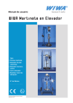
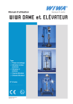
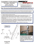
Operation manual
WIWA RAM and LIFT
Type:
❍ Ram Press
❍ Twin-Post Lift
❍ Single-Post Lift
❍ Lift Trolley
❍ Lift Cart
Serial-No.
_ _ _ _ _ _ _ _
Translation of the original operation manual
1302_RL_en • ski
Contents
1
Contents
1.1
Preface
This User’s Handbook must always be available to operating personnel!
The operating authority of the equipment must
ensure, that a User`s Handbook is available
to theoperator, in a language which he understands.
In the User’s Handbook, you can find all information requiredfor the proper handling of your
Ram Press
/
Lift /
Lift Trolley or
Lift Cart.
The manufacturer’s instructions and handling guidelines
for the paint or other material being processed must be
observed at all times.
No method of operation should be exercised which impairs
the safety of
products and the operating personnel.
1.2
Read before starting!
Always pay close attention to the instructions
and specifications found in the User's Handbook for the unit and any accessories!
Before each usage, be especially certain to:
➤➤ Check the seal and function of all connections andmounted parts.
➤➤ Observe the maximal allowed pressure of the unit and
➤➤ accessory parts.
Before beginning any work on the equipment and at
any pause during operation, be absolutely sure to:
➤➤ Cut off the the supply of compressed air to the lift / ram
press and set the operating lever (pict. 3.2.1 - 3.2.2, pos.
3) or the 3-way valve (pict. 3.2.5, pos. 11) to the "STOP"
postition
➤➤ If a pump is mounted to the lift / ram, close the inbound
air ball valve and depressurize the pump.
1.3
Table of contents
page
1Contents................................................................. 3
1.1Preface................................................................. 3
1.2
Read before starting!............................................ 3
1.3
Table of contents................................................... 3
2Safety..................................................................... 4
2.1
Description of symbols.......................................... 4
2.2
Warning instructions on the unit............................ 4
2.3
Dangers arising from the equipment..................... 4
2.4
Applications of the machine.................................. 4
2.5
Alterations, additions and emissions.................... 5
2.6
Sources of danger................................................ 6
2.7
Operating personnel............................................. 6
2.8
Installation site and handling of the unit and auxiliary items.............................................................. 7
2.9
Transporting the unit and accessory..................... 7
3
Unit descriptions................................................... 8
3.1
Available versions................................................. 8
3.2
Regulator Units................................................... 11
4
Assembly and Operation.................................... 12
4.1
Setting up............................................................ 12
4.2
Equipment preparation and operation - Ram
Press................................................................... 12
4.3
Preparation and operation - Lift.......................... 13
4.4
Follower plate / cover.......................................... 14
5
Shutting down..................................................... 16
6
Exchanging material container.......................... 16
7
Appendix.............................................................. 17
7.1
Inspection and maintenance............................... 17
7.2
Troubleshooting.................................................. 17
7.3
Technical Specifications...................................... 18
Copyright
© 2008 WIWA
Copyright ownership for this user manual remains with
WIWA WILHELM WAGNER GmbH & Co. KG
Gewerbestraße 1-3 • 35633 Lahnau
Phone: +49 (0)6441 609-0 • Fax: +49 (0)6441 609-50
This operating manual is solely intended for personnel involved in
preparation, operation and servicing.
It is prohibited to pass on this operating manual for reproduction,
utilisation or communication of its contents, unless this has been
explicitly permitted. Infringements incur an obligation to pay damage
compensation. All rights reserved in the event of registration of the
patented design, industrial design or registered design.
This operating manual only applies in conjunction with the machine
card that was given to you with the user manual for your equipment.
Please check that the type plate data is identical with the information on the machine card. Please notify us immediately if there are
discrepancies, if the user manual has been incorrectly compiled or if
the type plate is missing.
Translation of the original operation manual Ram/Lift/Lift Trolley
RL900 • en • 01.10 • cf
3
Safety
2
Safety
2.1
Description of symbols
The warnings and symbols used in this User's Handbook
have the following meaning:
Note
This marks a section of text which is especially
relevant to safety. Special attention should be paid
tothis section and its contents strictly abserved.
WARNING
This marks a situation which could be dangerous.
If not observed,death or very serious injuries could
result.
DANGER OF EXPLOSION
This marks a situation which could lead to explosion. Special attention should be given and the warning strictly observed.
ELECTRICAL VOLTAGE
This marks a situation which could lead to explosion through electrostatic charging.
Special attention should be given and the warning
strictly observed.
HOT SURFACE
This marks a situation which could lead to burns
from hot surfaces.
Special attention should be given and the warning
strictly observed.
WEAR PROTECTIVE GLOVES
Protective gloves with lower arm protection must
be worn to prevent burn injuries. Special attention
should be given and the warning strictly observed.
2.2
Warning instructions on the unit
➤➤ Warning signs and symbols which have been placed on
the unit are there to inform of possible dangers and must
be observed.
➤➤ Warning signs and symbols may not be removed.Damaged and illegible warning signs and symbols are to be
replaced immediately.
The following signs are located on the unit:
➤➤ Nameplate (Picture 2.2.1)
Please observe that the information located on the nameplate corresponds to data
found on the machine card
(Chapter "Technical Specification").
Picture 2.2.1
We request immediate notification should there be any
discrepancies or if the nameplate is missing.
4
➤➤ Plastic sign: „AB / DOWN - STOP - AUF / UP“
(Picture
2.2.2)
The sign shows the direction of travel depending on the
position of the operating lever.
AB /DOWN: The lift / ram travels downwards.
STOP:
The lift / ram stops at the desired position.
AUF /UP: The lift / ram travels
upwards
Picture 2.2.2
2.3
Dangers arising from the equipment
This unit was designed and built in accordance with all safety aspects.
It corresponds with the present standards of technical
regulations and current rules for accident prevention. It left
the factory in perfect condition and warrants a high level
of safety. However, the following dangers exist if operated
incorrectly or used inappropriately:
➤➤ Risk of physical injury or death to the operator or thirdpersonsorr third persons
➤➤ Risk of damage to the unit and other property belonging
to the owner
➤➤ Risk of malfunction or reduced operational efficiency
All personnel involved in the starting, operation and
maintenance of the unit must read the following notes
carefully and observe them.
It is a matter of their safety! We recommend that the
managers responsible for the proper operation of the unit
have this confirmed in writing.
In addition to the instructions found in this User's
Handbook, all instructions and guidelines loacted in
manuals covering accessory and/or auxillary items are
to be followed closely.
As a rule of thumb, no action is to be permitted that could
endanger
products or operating personnel.
2.4
Applications of the machine
Ram Press
The ram press simplifies the processing of poorly flowing materials, such as grease, mastics, high-viscosity
materials, etc.
Depending on the model, a follow plate / follow cover is
guide into the material container with the aid of compressed
air. All necessary accessories are mounted on the follow
plate / follow cover. A force feeding of the material into the
pump follows.
Translation of the original operation manual Ram/Lift/Lift Trolley
RL900 • en • 01.10 • cf
Safety
Lift
Lifts are used to raise pumps and accesories.
Ram Press and Lift
The follow plate / follow cover enable the use of several
components at the same time in the feed container, such as
a pump, agitator and level indicator.
Available accessories include:
➤➤ High-pressure pumps
➤➤ Extrusion pumps
➤➤ Low-pressure pumps
➤➤ Pneumatic geared agitators
➤➤ Electric geared agitators, etc.
All accessories are available in a variety of sizes / power ratings and are not included with the purchase of a ram press
or lift.
To exchange the material container, the follow plate / follow
cover (ram press) or the drum cover (lift), together with the
mounted accessories, are lifted with the aid of compressed
air.
Using this equipment in areas requiring
protection from explosions
Marking:
II 2G cT4
This equipment fulfills the explosion-proof requirements found in the guideline 94/9/EC for the type of
explosion, equipment catagory and temperature class
found on the nameplate).
This equipment is able to be installed in areas requiring
Zone I explosion protection. Due to the possibility that explosive gases and overspray may be created, this unit is to
be considered as Group II, Equipment Catagory 2G.
The flash point for the materials being sprayed, as well as
the solvent being used, must be above 200°C.
When operating this equipment, the User‘s Handbook must
be followed closely.
The required inspection and maintenance intervals
must be adhered to strictly.
All information found on the unit‘s signs or plates must
be adhered to and not exceeded. Do not allow this unit
to be overloaded. It is the responsibility of the operator of
this equipment to determine the explosion risk (zone determination according to EC regulation 94/9/EC,
Appendix II, Nr. 2.1-2.3) in the area of usage, in accordance
with local regulatory authority guidelines. Furthermore, it
is the responsibility of the operator on-sight to check
and ensure that the technical specifications and markings according to ATEX are compliant with local requirements.
Please observe that some components have their own nameplate with separate markings according to ATEX.
ving strangely during operation, the unit must be shut
down immediately and
Customer Service contacted as soon as possible.
Other usage is not in line with regulations. Before
equipment is used for other purposes or with other materials, and, therefore, not according to the regulations, permission should be obtained from the manufacturer as the
guarantee is otherwise invalid. The observation of technical
documentation and the compliance with specified operational, maintenance and starting guidelines are manditory in
accordance with the valid regulations.
2.5
Alterations, additions and emissions
Rebuilds and changes
For safety reasons, it is not allowed to carry out rebuilds or
changes without authorization.
Protective equipment may not be dismounted, changed or
neglected.
If using components which are not produced or delivered by
, warranty coverage is negated as well as liability.
The machine may only be operated within the prescribed
limits and machine parameters.
Danger caused by attachments and spare parts
If you use original attachments and original spare parts from
, the compatability with our equipment is guaranteed. It is, however, essential that the safety regulations of
the attachments and spare parts are observed. You can find
these safety regulations in the User’s Handbook located
with the spare parts lists.
If you use attachments and spare parts from another source,
cannot guarantee the safety of the entire system.
In this case, our guarantee does not cover any damage or
injury caused by such attachments and spare parts.
Emissions
The
Single and Twin-Post Ram Presses, as well
as the Twin-Post Lift, operate practically noise-free.
The operator is responsible for compliance with the rules
covering the prevention of accidents due to „noise“ (BGR
500, Chap. 2.25). Therefore, pay special attention to the
environmental conditions at the site, e. g. noise can be increased if the machine is installed in or on hollow bodies.
The marking with the lowest rating for explosion protection becomes valid for the entire system. If the intended application could lead to injury of personnel if this
equipment malfunctions, on-sight precautions and preventive measures must be implemented
If this equipment appears to be malfunctioning or behaTranslation of the original operation manual Ram/Lift/Lift Trolley
RL900 • en • 01.10 • cf
5
Safety
2.6
Sources of danger
Please remember that the equipment operates with
compressed air and that the accessories (i.e. airless
high pressure pump) may operate with very high
pressures which could cause severe injury if used
improperly.
Observe and follow these instructions:
➤➤ The raising and lowering of the unit, as well
as falling objects, can cause severe injury and
property damage.
➤➤ Persons or other living creatures should
never be placed on the frame or within the
lifting range of this equipment.
➤➤ Persons or other living creatures should
never be raised or lowered using this equipment.
➤➤ When the traverse is moving up or down, crushing danger can arise in certain areas of the machine due to inattention.
➤➤ Never place fingers, hands or other body parts
between following plate / cover and container rim,
frame and drum cover, traverse and piston rod or
traverse and upper tube for air supply.
➤➤ Take care that no clothing or other object comes between the following plate / cover and the container
rim.
➤➤ The release of pressurized material, as well as contact
with rotating parts, can cause severe injury.
➤➤ Please mount accessories only when the equipment
has been turned off. During assembly, the accessories must also be turned off and depressurized.
➤➤ Observe and follow the instructions in the User's
Handbook for this equipment and any accessories,
such as agitators, pumps, etc.
➤➤ If accessories are removed from the material container
with the motor still in operation, material or loose parts
can be thrown out and cause severe injury and property
damage.
➤➤ Whenever the traverse is in motion (upward or
downward) all mounted components must be turned
off and not moving!
➤➤ All mounted components must be secured to the following plate / cover before the traverse is placed in motion.
No loose components may be transported!
➤➤ In case electric agitators, heaters or other electric accessories are installed, the explosion-proof
rating
must
be
checked.
Connectors for heaters, agitators, etc., which are not explosion-proof may only be used outside of rooms which
fall under explosion-proof ordinances, even though the
accessory equipment may be explosion-proof.
6
➤➤ Do not exceed the maximum allowed lifting weight of the
machine. Exact details can be found in Chap. "Technical
Specifications".
➤➤ Uncontrolled raising and lowering can cause overheating due to friction and lead to fire or expolosion.
➤➤ Raise and lower the traverse only when needed to avoid
unnecessary friction.
➤➤ Operation of this equipment in a closed area can lead to
danger caused by explosive atmospheres, resulting in
possible severe injury and property damage.
➤➤ Smoking, open flames or other sources of ignition are
not allowed in the area where the unit is operating.
➤➤ If operated outdoors, a lightning strike can present danger.
Never operate the unit during a thunderstorm.
2.7
Operating personnel
Authorized personnel
People under the age of 16 should not operate this equipment. The management in charge of the operation of the
unit must make the User’s Handbook available to the operator and must make sure that he has read and understood it.
Only then may the system be put into operation. We recommend the manager has this confirmed in writing. The
operator is obliged to report any changes to the unit which
might affect its safety to the manager, as he must ensure
that the machine is functional.
The procedural responsibilities for operating the unit must
be laid down clearly and adhered to. No unclear competences may remain, as these could endanger the safety of
the users.
The operator must make sure that only authorised persons
work with the unit. He is responsible for third parties in the
working vicinity of the system.
The operator of the equipment is obliged to repeat instructions about dangers and safety measures at regular intervals (at least once a year, for juveniles twice a year).
Personal protective equipment
We call to your attention that the valid guidelines and regulations covering the site of operation (mining, closed areas
etc.) must be adhered to.
Translation of the original operation manual Ram/Lift/Lift Trolley
RL900 • en • 01.10 • cf
Safety
2.8
Installation site and handling of the unit
and auxiliary items
Installation site
To prevent equipment damage or severe injury
during installation of the maschine, the following must be observed:
➤➤ The installation and mounting of the machine may becarried out by trained operating personnel only, in accordance with all safety instructions.
➤➤ Before beginning with installation of the machine, it must
be inspected for transport damage.
➤➤ Read and observe the Chapter “Safety".
Safety measures on-site
➤➤ The system must have a secure position and sufficient
space to ensure safe operating.
➤➤ Anchor the
Single- and Twin-Post Ram Presses, or the Twin-Post Lift to the foundation at the installation site using 4 bolts (M12). Mounting holes are found
in the base plate of the unit (picture 2.8.1)
Holes for
mounting
Holes for
mounting
Picture 2.8.1 Base plate
➤➤ Mobile
versions:
Lock the wheels at the desired location using
your foot to press down on each wheel brake.
This prevents unwanted movement of the unit.
Prior to transport of the unit, the wheels must be released by pulling upwards on each brake.
➤➤ The owner of this equipment must ensure that it is properly gounded and protected from lightning.
➤➤ Keep the working area, especially all gangways and
standing areas, clean.
Remove spilled paint or solvent immediately.
➤➤ Comply strictly with the current rules for accident
prevention
Handling of the unit and auxiliary items
➤➤ Adapting the unit to different production requirements,
as well as servicing and cleaning, may only be done by
trained operating personnel.
➤➤ Maintenance and repair may only be performed by
trained and qualified personnel.
➤➤ Before starting such work as above, the supply of compressed air to the unit must be shut-off.
➤➤ The function of all safety features, as well as unit itself,
must be checked after completing any work on the unit.
2.9
Transporting the unit and accessory
Observe and follow these instructions to prevent equipment damage or severe injury during
transportation!
➤➤ Transportation may only be carried out by qualified and
authorized personnel.
➤➤ Cut off the supply of compressed air to the unit, even if
transporting for short distances.
➤➤ Remove coating material containers and loose parts before loading!
➤➤ Be careful when loading, whether a hoist is being used
or not!
➤➤ Only use suitable transportation vehicles with sufficient
load capacity.
➤➤ Secure the unit to the transporting vehicle against slipping and falling down.
➤➤ When loading the machine with hoisting devices, pay
attention to the maximum allowable load capacity. Place
two appropriately rated hoisting belts around the frame
tube (Picture 2.9.1 - applies only to Twin-Post Ram
Press or Lift).
➤➤ The weights of the the
Single- and Twin-Post
Ram Presses and the Twin-Post Lift are found in Chapter "Technical Specifications". The total weight of the
unit, including all accessories, must be calculated before transport. The individual weights are found in the
User's Handbook for each accessory component.
➤➤ Never transport the unit using lifting eyes found on accessory components (feed pump, etc.) These lifting
points are not suitable for lifting the total weight of the
unit.
➤➤ Never stand under raised loads or in the direct lifting
area. Block and mark the transport route so that unauthorised persons do not enter the danger zone. Nonobservance leads to danger of injury!
➤➤ Parts or equipment dismounted for transportation purposes must be properly remounted by trained personnel
before start-up.
Belts to be place around
this tube
Base plate
Picture 2.9.1
Translation of the original operation manual Ram/Lift/Lift Trolley
RL900 • en • 01.10 • cf
7
Unit descriptions
3
3.1
Unit descriptions
Available versions
Twin-Post Ram Press
Picture 3.2.1
Picture 3.1.1: Twin-Post Ram Press - Capacity: 0,3t
Picture 3.2.1
Picture 3.1.2: Twin-Post Ram Press - Capacity: 0,75t
Pos.
Picture 3.2.1
Picture 3.1.3: Twim-Post Ram Press - Capacity: 2,5t
Description
1
Frame
2
Traverse
3
Press Rod
4
Holder for mounting kit
5
Drum holder (accessory)
6
Air hose
7
Hose sleeve
8
Plug handle
9
Follow plate (accessory)
10
Piston
11
Floor plate
Single-Post Ram Press
Picture 3.2.1
Picture 3.2.1
Picture 3.1.4: Single-Post Ram Press Capacity: 0,375t, for 216,5 l-gal.drum
8
Picture 3.1.5: Single-Post Ram Press Capacity: 0,375t, for 60 l-container
Translation of the original operation manual Ram/Lift/Lift Trolley
RL900 • en • 01.10 • cf
Unit descriptions
Twin-Post Lift
Picture 3.2.4
Picture 3.1.6: Twin-Post Lift for Drum Cover Capacity: 0,75 t, for 216,5 ltr. gal.drum
Pos.
Picture 3.2.4
Picture 3.1.7: Twin-Post Lift
Capacity: 0,75 t, for 216,5 ltr. gal.drum
Description
1
Frame
2
Traverse
3
Press Rod
4
Holder for Mounting Kit
10
Piston
11
Floor plate
12
Drum cover (accessory)
Single-Post Lift
Picture 3.2.4
Picture 3.2.4
Picture 3.1.8: Singe-Post Lift for Drum Cover Capacity: 98 kg
Elevating height: 930 mm
Picture 3.1.9: Single-Post Lift for Dum Cover
Capacity: 98 kg /
Elevating height: 600 mm
Translation of the original operation manual Ram/Lift/Lift Trolley
RL900 • en • 01.10 • cf
9
Unit descriptions
Lift Trolley
Picture 3.2.1
Picture 3.2.5
Picture 3.1.10: Lift Trolley - Lift version Capacity: 0,3 t, for 60 ltr. container
Picture 3.1.11: Lift Trolley - Ram Press version
Capacity: 0,3 t, for 60 ltr. container
Picture 3.2.1
Picture 3.2.2
Picture 3.1.12: Lift Trolley - Ram Press / automatic version Capacity: 2,5 t, for 60 ltr. container
Picture 3.1.13: Lift Trolley - Ram Press version
Capacity: 0,75 t for 60 ltr. container
Lifting cart
Picture 3.2.5
Picture 3.1.14: Lifting cart
Capacity: 62,5 kg
10
Translation of the original operation manual Ram/Lift/Lift Trolley
RL900 • en • 01.10 • cf
Unit descriptions
3.2
Regulator Units
for Ram Press, Picture 3.2.1
for Lifting Cart, Picture 3.2.5
for Ram press / version with front plate and auto¬matic
function, Picture 3.2.2
for Ram Press / version with valve on ram and pump activation by spray gun, Picture 3.2.3
Push-rod valve on spray gun
for Lift, Picture 3.2.4
Roller-lever valve on ram
Pos.
Description
1
Rotary valve
2
Shut-off valve for air supply to follow plate or follow cover
3
Air pressure regulator
4
Air pressure gauge
5
Air connector
6
Switch for manual pump operation
7
Connection for automatic spray gun
P = compressed air
8
Connection for automatic spray gun
A = Drain/Circulate
9
Roller lever valve
10
Shut-off valve for air supply
11
3-way valve
Translation of the original operation manual Ram/Lift/Lift Trolley
RL900 • en • 01.10 • cf
11
Assembly and Operation
4
Assembly and Operation
4.1
Setting up
Job
You wish to erect the machine at the site and prepare it for
operation.
Prerequisite
All necessary accessories (follower plate / cover, pump,
agitator, etc.) are onhand.
Procedure
➤➤ Place the machine on an even and solid surface.
Only use M12 bolts (mech. strength class 8.8) to anchor
the unit's base plate to the floor.
➤➤ All operational elements must be easily accessible.
➤➤ Only use oiled compressed air. Never use bottled
gas (i.e. oxygen or propane) for air supply to the unit.
➤➤ To ensure that sufficient air is supplied, the rating of
the compressor must be compared to the unit's air
consumption rate.
➤➤ The diameter of the air supply hose must match the
connections on the unit.
➤➤ The equipment can be placed inside or outside of
spraying booths.
➤➤ Weight and dimensions of the unit can be found in
Chap. "Technical Specifications".
➤➤ Inspect all nuts, bolts, hose connections and other turnable parts for tightness.
4.2
Equipment preparation and operation Ram Press
Job
The unit is to be prepared for operation.
Prerequisite
All necessary accessories (follower cover/plate, pump, agitator, etc.) are mounted and the material to be processed
is onhand.
➤➤ For models with front plate and automatic function:
➤➤ Connect the pneumatic hoses to the valve of the
spray gun and on the connections of the front plate
(Picture 3.2.2, pos. 7 + 8)
➤➤ Compressed air to the fitting marked “P“
➤➤ Drain/circulate on the fitting marked “A“
12
➤➤ For models with valves on the ram press and spray gun
for activation of the pump (Picture 3.2.3):
➤➤ The roller lever valve on the ram press is connected
with the spray gun and further to the air supply side
of the air maintenance unit on the pump.
Procedure
Special instructions for the
Twin-Post Ram
Press:
To prevent unwanted lifting of the material container,
i.e. the drum lifting from the base plate when the traverse moves upward, we recommend that a drum
retaining ring (accessory) be installed on the ram
press. The corresponding order number is found in
the specification sheet, or can be provided by your
customer service representative or directly
from the
factory.
➤➤ Ensure that the air supply is turned off:
➤➤ Turn the adjusting knob on the air pressure regulator to the left until it turns freely and all pressure is
released
➤➤ Set the operating lever (c, pos. 3) or the 3-way valve
(Picture 3.2.5, pos. 11) to the “STOP“ position.
➤➤ Check for proper connection of all accessories.
➤➤ Connect the air supply line to the air supply fitting (Picture 3.2.1 - 3.2.5, pos. 5).
➤➤ Switch on the air supply to the equipment.
➤➤ Adjust the air pressure regulator (Picture 3.2.1 + 3.2.2,
pos. 3) to a pressure of 2 bar.
➤➤ Set the operating lever (Picture 3.2.1 - 3.2.2, pos. 3) or
the 3-way valve (Picture 3.2.5, pos.11) to the "UP" position. The traverse (together with mounted components)
moves upwards.
➤➤ Set the operating lever (Picture 3.2.1 - 3.2.2, pos. 3) or
the 3-way valve (Picture 3.2.5, pos.11) to the "STOP"
position as soon as enough free space is reached between the traverse (incl. mounted components) and the
top of the drum / container.
➤➤ Place the drum / container onto the base plate so that it
rests against the lift's drum stop.
➤➤ Set the operating lever (Picture 3.2.1 - 3.2.2, pos. 3) or
the 3-way valve (Picture 3.2.5, pos. 11) to the "DOWN"
position. The traverse lowers the mounted components
into the drum / onto the container.
Pay attention to correct seating of the follower
plate/cover in the material container/drum.
When the traverse is moving up or down,
crushing danger can arise in certain areas of
the machine due to inattention.
➤➤ Never place fingers, hands or other body
parts between: following plate / cover and
container rim, frame and drum cover, traverse and piston rod, traverse and upper
tube for air supply.
➤➤ Take care that no clothing or other object
comes between the following plate / cover
and the container rim.
Translation of the original operation manual Ram/Lift/Lift Trolley
RL900 • en • 01.10 • cf
Assembly and Operation
➤➤ Set the operating lever (Picture 3.2.1 - 3.2.2, pos. 3) or
the 3-way valve (Picture 3.2.5, pos. 11) to the "STOP"
position as soon as the following plate / cover rests on
top of the drum/container.
➤➤ Unscrew the plug (Picture 3.1.2 + 3.1.3, pos. 8) from the
follower plate / cover to bleed any air from the material
container or drum.
➤➤ Set the operating lever (Picture 3.2.1 - 3.2.2, pos. 3) or
the 3-way valve (Picture 3.2.5, pos. 11) to the “DOWN“
position and lower the accessories slowly into the material container or drum.
➤➤ Set the operating lever (Picture 3.2.1 - 3.2.2, pos. 3) or
the 3-way valve (Picture 3.2.5, pos.11) to the “STOP“
position as soon as the material comes out of the bleed
hole in the following plate / cover.
➤➤ Screw the plug (Picture 3.1.2 + 3.1.3, pos. 8) back into
the follower plate / cover.
➤➤ Set the operating lever (Picture 3.2.1 - 3.2.2, pos. 3) or
the 3-way valve (Picture 3.2.5, pos. 11) to the “DOWN“
position.
➤➤ Adjust the air pressure regulator (Picture 3.2.1 + 3,2,2,
pos. 3) to the desired operating pressure.
The maximum allowed operating pressure of the
ram press is 8 bar / 116 psi.
Result
The start-up is complete.
You may now operate any mounted accessories. Observe
and follow the instructions in the User's Handbook for each
of the accessories
For versions with front plate and automatic
function:
➤➤ The connected pump operates only when the
gun is triggered and downwards movement of
the ram press.
➤➤ When the ram reaches the lowest position, a
contact on the roller lever valve/spring pin valve
(Picture 3.2.2, pos. 9) shuts off the pump.
➤➤ To manually operate the pump (for example, to completely empty the material container), press the button on the operating
panel of the ram press (Picture 3.2.2, pos. 6).
Releasing the button will again shut off the
pump.
.
4.3
For versions with valves on the ram press and
spray gun for activation/deactivation of the
pump:
➤➤ The connected pump operates only when the
gun is triggered and there is movement of the
ram within the travel limits set by the roller lever
valve.
➤➤ The connected pump shutts off when:
➤➤ The ram is in the lowest position,
➤➤ The trigger of the spray gun is released.
Attention!
If the spray gun is triggered while the ram is in
upward travel, the pump will draw air and must
be bled before the next use.
Therefore, the trigger must be secured before
and during upward movement of the ram (for
example, on changing of the material container).
Read and follow the instructions in the user‘s hanbooks for the spray gun and pump.
Preparation and operation - Lift
Task
Prepare the equipment for operation.
Prerequisite
All necessary accessories (drum cover, pumpe, agitator,
etc.) for the twin-post lift are mounted and the material to be
processed is onhand.
Procedure
➤➤ Interrupt the air supply to the equipment:
➤➤ Turn the ball valve (Picture 3.2.4, pos. 10) to the
“CLOSED“ position.
➤➤ Adjust the rotary valve (Picture 3.2.1 - 3.2.2,
pos. 3) or the 3-way valve (Picture 3.2.5, pos. 11) to
“STOP“.
➤➤ Check for proper connection of all accessory items.
If any accessories outside of the material container (i.e. agitator) are in motion, clothing may
be caught or material splattered.
This can lead to severe injury or property damage.
➤➤ Turn off all accessories before any upward
or downward movement of the lift and wait
until they are no longer in motion.
➤➤ Connect the air supply line to the air supply fitting (Picture 3.2.1 - 3.2.5, pos. 5).
Translation of the original operation manual Ram/Lift/Lift Trolley
RL900 • en • 01.10 • cf
13
Assembly and Operation
➤➤ Switch on the air supply to the equipment at the ball
valve (Picture 3.2.4, pos. 10).
➤➤ Set the operating lever (Picture 3.2.1 - 3.2.2, pos. 3) or the
3-way valve (Picture 3.2.5, pos. 11) to the "UP" position.
The traverse (together with mounted components)
moves upwards.
➤➤ Set the operating lever (Picture 3.2.1 - 3.2.2, pos. 3) or
the 3-way valve (Picture 3.2.5, pos. 11) to the "STOP"
position as soon as enough free space is reached between the traverse (incl. mounted components) and the
top of the drum / container.
➤➤ Place the drum / container onto the base plate so that it
rests against the lift's drum stop.
➤➤ Set the operating lever (Picture 3.2.1 - 3.2.2, pos. 3) or the
3-way valve (Picture 3.2.5, pos. 11) to the "DOWN" position.
The traverse lowers the mounted components into the
drum / onto the container.
4.4
Follower plate / cover
Job
A follower plate / cover should be mounted to or exchanged
on a Ram Press.
Prerequisite
The following items are necessary:
➤➤ 1 Follower Plate or Cover
➤➤ 1 Mounting Kit for Follower Plate or Cover
Picture 4.1.1
Follower cover
(for 216,5 L drum)
When the traverse is moving up or down,
crushing danger can arise in certain areas of
the machine due to inattention.
➤➤ Never place fingers, hands or other body
parts between: following plate / cover and
container rim, frame and drum cover, traverse and piston rod, traverse and upper
tube for air supply.
➤➤ Take care that no clothing or other object
comes between the following plate / cover
and the container rim.
Picture 4.4.2
Follower plate
(not for single-post lifts)
1
2
➤➤ Set the operating lever (Picture 3.2.1 - 3.2.2, pos. 3) or
the 3-way valve (Picture 3.2.5, pos. 11) to the "STOP"
position as soon as the following plate / cover rests on
top of the drum/container.
Result
The start-up is complete.
You may now operate any mounted accessories. Observe
and follow the instructions in the User's Handbook for each
of the accessories.
Picture 4.4.3
Folower plate
(only PFP)
Pos.
Beschreibung
1
Hose connection
2
Handle for bleed valve
The use of a follower plate or cover is very specific to the
application. The appropriate mounting kits must be ordered
for the accessories used.
Contact your
Customer Service Center or the
factory directly for the correct order numbers for
the follower plate / cover and mounting kits.
Procedure
Mounting and/or disassembly may only be performed when the unit is shut off!
All accessories must be shut off and pressure released.
Observe all warning found in the chapter "Safety".
➤➤ Perform all steps found in chapter 4.1.
➤➤ Lower the traverse to its lowest position.
➤➤ Set the operating lever (Picture 3.2.1 - 3.2.2, pos. 3) or
the 3-way valve (Picture 3.2.5, pos. 11) to the "STOP"
position.
14
Translation of the original operation manual Ram/Lift/Lift Trolley
RL900 • en • 01.10 • cf
Assembly and Operation
➤➤ Cut off the air supply to the unit and turn the control
knob on the pressure regulator counter-clockwise until
it turns freely.
➤➤ According to version:
➤➤ Attach the follower plate to the pressure 3.1.2 +
3.1.3, pos. 3) or
➤➤ Mount the follower plate / cover directly to the material pump by using a mounting kit.
➤➤ Attach the mounting kit for the ram press to the holder
(Picture 3.1.2 + 3.1.3, pos. 4).
➤➤ Mount accessory components (i.e. pump) to the ram
press mounting assembly.
➤➤ Connect the air hose to the hose fitting (Picture 4.4.1 +
4.4.2, pos. 1) on the follow plate / cover.
➤➤ Proceed as described in Chapter 4.2.
➤➤ Contact with solvent or water can damage the
equipment. Do not use materials containing solvent to clean the equipment and do not spray
the equipment using high-pressure or water.
Electrically heated follow plate
Observe the following when using an electrically heated follow plate:
Through use of an electrically heated follow plate, high-viscosity can be heated and made to flow more easily.
The heating takes place through a special heater mounted
in the follow plate.
The temperature can be adjusted by a temperature regulator (optional).
The electrically heated follow plate is suitable for use with
216,5 L drums.
➤➤ The equipment may not be used in areas where
there is danger of .
➤➤ The heating of materials containing or flammable materials can lead to explosion, causing severe injury and property damage.
Follow the processing instructions in the
manufacturer‘s material data sheet-especially
the information concerning the max. working temperature (flash point) of the material.
Take care that the adjusted temperature for the
heater is lower than the manufacturer‘s stated
flash point.
➤➤ The connection of the equipment to the power
supply may only be performed by properly trained.
Observe
the
stated
power
rating
when
conecting
the
equipment.
The equipment must be turned off before connecting to the power supply.
➤➤ Turn off the equipment prior to all maintenance
abd repair work.
➤➤ Danger
of
burn
injury!
The temperature of the follow plate surfaces,
as well as the drum, can reach the max. adjusted temperature of up to 80°C. For this reason,
always wear the proper protective hand and
lower arm protection.
Translation of the original operation manual Ram/Lift/Lift Trolley
RL900 • en • 01.10 • cf
15
Shutting down
5
Shutting down
Task
Shut down the equipment after operation.
Prerequisite
Follow the shutdown procedure at each interupption of
work.
Procedure
➤➤ Turn off all accessories (i.e. high pressure pump).
Observe and follow the instructions in the User's
Handbook for each of the accessories.
Ram Press
➤➤ Set the operating lever (Picture 3.2.1 - 3.2.2, pos. 3) or
the 3-way valve (Picture 3.2.5, pos. 11) to the "STOP"
position. for versions with automatic function:
➤➤ Trigger brieflythe automatic spray gun.
➤➤ Adjust the air pressure regulator (Picture 3.2.1 + 3.2.2,
pos. 3) to 0 bar.
Lift
➤➤ Set the operating lever (Picture 3.2.1 - 3.2.2, pos. 3) or
the 3-way valve (Picture 3.2.5, pos. 11) to the "STOP"
position.
➤➤ Close the ball valve (Picture 3.2.4, pos. 10)
6
Exchanging material
container
1. Shut down
➤➤ Follow all steps
(see Chapter 5).
of
the
shut
down
procedure
➤➤ Ram Press
➤➤ Open the ball valve (Picture 3.2.1 + 3.2.2, pos. 2).
➤➤ Adjust the air pressure regulator (Picture 3.2.1 +
3.2.2, pos. 3) to2 bar.
➤➤ Set the operating lever (Picture 3.2.1 - 3.2.2,
pos.
3)
or
the
3-way
valve
(Picture 3.2.5, pos. 11) to the "UP" position.
Compressed air enters the empty drum and assists
the upward movement of the follow plate/follow cover with accessories.
➤➤ As soon as the follow plate/follow cover with accessories is above the rim of the container:
➤➤ Close the ball valve (Picture 3.2.1 + 3.2.2,
pos. 2).
➤➤ Set the operating lever (Picture 3.2.1 - 3.2.2,
pos. 3) or the 3-way valve (Picture 3.2.5,
pos. 11) to the "STOP" position.
➤➤ Exchange the material container/drum.
➤➤ Lift
➤➤ Open the ball valve (Picture 3.2.4, pos. 10) on the
lift.
➤➤ Set the operating lever (Picture 3.2.1 - 3.2.2,
pos. 3) or the 3-way valve (Picture 3.2.5, pos. 11) to
the "UP" position.
➤➤ The lift raises the drum cover with accessories from
the material container/drum.
➤➤ Raise the lift enough that the accessories are no longer inside the container/drum.
➤➤ Close the ball valve (Picture 3.2.4, Pos. 10) on the
lift.
➤➤ Set the operating lever (Picture 3.2.1 - 3.2.2,
pos. 3) or the 3-way valve (Picture 3.2.5, pos. 11) to
the "STOP" position.
➤➤ Exchange the material container/drum.
3. Start up
➤➤ Follow all steps of the start up (Chapter 4).
2. Exchanging material container or drum
If any accessories outside of the material container (i.e. agitator) are in motion, clothing may
be caught or material splattered.
This can lead to severe injury or property damage.
➤➤ Turn off all accessories before any upward
or downward movement of the lift and wait
until they are no longer in motion.
We recommend that the follow plate/cover be externally cleaned with the material manufacturer‘s
recommended cleaner at each exchange of material container or drum.
16
Translation of the original operation manual Ram/Lift/Lift Trolley
RL900 • en • 01.10 • cf
Appendix
7
Appendix
7.1
Inspection and maintenance
The equipment must be inspected:
➤➤ prior to initial start up
➤➤ after modifications or repair of components which affect
the safety of the unit,
➤➤ after an interruption of operation of more than 6 months,
➤➤ as a minimum every 12 months.
For non-operational equipment, the inspection may de postponed until the next start up.
The results of the inspection must be recorded in writing
and retained until the next inspection.
The inspection certificate must remain at the operating location of the equipment.
7.2
Troubleshooting
Fault
Equipment doesn‘t raise or lower
Possible Cause
➤➤ No air supply connected
➤➤ Operating control „STOP“ position
➤➤
➤➤
➤➤
➤➤
➤➤ Connect air supply
➤➤ Place operating control in position
„UP“ or „DOWN“
Ram press: Air pressure regulator ➤➤ Ram press : Open air pressure
closed
regulator
Lift: air supply ball valve is closed
➤➤ Lift: open air supply ball valve
Air pressure adjusted too low
➤➤ Increase air pressure adjustment
Piston rod seals worn
➤➤ Replace piston rod seals (apply acid-free grease to piston rods prior
to assembly)
Translation of the original operation manual Ram/Lift/Lift Trolley
RL900 • en • 01.10 • cf
Solution
17
Translation of the original operation manual Ram/Lift/Lift Trolley
RL900 • en • 01.10 • cf
Noise level: Equipment operates practically noise-free
* = without floor plate
1010
Lifting cart
1580
Twin post lift - 0,75 T
1050
1135
Single post lift - 98 kg / lift range 600 mm
1215
1700
Single post lift - 98 kg / lift range 930 mm
Lift trolley version
1630
Twin-post ram press - 2,5 T - Automatic
Ram trolley version - 0,75 t
975
Twin-post ram press - 0,75 T / 60 ltr.
1185
1580
Twin-post ram press - 0,75 T / 216 ltr.
Ram trolley version - 2,5 t - automatic
940
Twin-post ram press - 0,3 T
1050
1560
Ram trolley version - 0,3 T – automatic
1065
Single-post ram press for 216,5 ltr. drum
approx.
height(mm) fully
lowered
Single-post ram press for 60 l - container
Equipment
approx. Height
(mm) fully raised
1420
1730
1865
1815
1730
2570
1750
2650
2600
1625
2570
1670
2600
1760
490
885
910
1055
885
660
160*
160*
830
670
660
665
200
160
approx. width
(mm) (Bottom
plate / cart)
550
860
890
855
860
1000
160*
160*
1250
650
1000
500
200
160
approx. length
(mm) (floor plate
/ trolley)
18
approx. weight.
(kg)
235
235
113
300
113
113
41
Connection Ratings /
Performance
6,5
8
8
8
8
8
5
5
8
8
8
8
8
8
max. air inlet
pressure (bar)
0,0625
0,3
0,75
2,5
0,3
0,75
0,098
0,098
2,5
0,75
0,75
0,3
0,375
0,375
7.3
max. lift capacityat max. max.
air pressure (t)
Dimensions and Weight
Appendix
Technical Specifications
Appendix
Translation of the original operation manual Ram/Lift/Lift Trolley
RL900 • en • 01.10 • cf
19
Your contacts throughout the world
Michel Laksander
Sales Representative
France
2 Bis rue de léglise
F-02240 Brissy Hamegicourt, France
Tel.: +33 32 36 21 120
Mobil: +33 63 70 19 297
E-Mail: [email protected]
Wolfgang Pucken
Sales Director
North of Germany, Israel, Hungary, Romania, Turkey, Poland,
Malta, India, Pakistan, Africa, Morocco
Frankenstraße 37
53359 Rheinbach-Oberdrees, Germany
Mobil: +49 173 5432559
Tel.: +49 2226 12708
Fax: +49 2226 13973
Robert Jansen
Sales Director
Finland, Sweden, Norway, Denmark, Scotland, England,
Holland, Belgium, France, Spain/Portugal, Italy, Croatia,
Greece, Czech Republic, Slovakia, Slovenia, Luxembourg,
Bulgaria, Egypt, Libya, Dubai, Abu Dhabi, Catar, Bahrain,
Kuwait, Saudi Arabia, Iran, Oman
Headquarter and production
WIWA Wilhelm Wagner GmbH & Co. KG
Gewerbestr. 1 - 3
35633 Lahnau, Germany
Tel.: +49 6441 609-0
Fax +49 6441 609-50
E-Mail: [email protected]
Homepage: www.wiwa.de
WIWA partnership in USA
WIWA LP
107 N. Main St.
P.O. Box 398, Alger, OH 45812
Tel.: +1 (419) 757-0141
Fax: +1 (419) 549-5173
Toll Free: +1(855) 757-0141
E-Mail: [email protected]
Homepage: www.wiwalp.com
WIWA subsidiary in China
WIWA Taicang Co., Ltd.
Building A of Huaxin Industrial Park
No.11 East Qingdao Road, Taicang City
Jiangsu Province 215400, P.R.China
Tel.: +86 512-5354 8858
Fax: +86 512-5354 8859
E-Mail: [email protected]
Homepage: www.wiwa-china.com
WWW.WIWA.DE
Rietgans 38
3752 KH Bunschoten, Netherlands
Mobil: +31 6 18 88 40 97
Tel.: +31 33 494 69 81
Fax: +31 33 494 75 83
E-Mail: [email protected]
Otto Dietrich
Sales Director
Russia, Ukraine, Belarus, Moldavia, Lithuania, Latvia, Estonia,
Azerbaijan, Georgia, Armenia, Kazakhstan, Uzbekistan,
Kyrgyzstan, Turkmenistan, Tajikistan
Lindenhof 6
56154 Boppard, Germany
Mobil: +49 160 1574385
Tel.: +49 6742 899336
Fax: +49 6742 899337
E-Mail: [email protected]
John Berry
Sales Director
Mexiko, Mittelamerika
Callejon del Arrastradero 204
Col. Ocotepec, Morelos
Cuernavaca, 62220, Mexico
Mobil: +52-777-289-4275
Tel./Fax: +52-1-777-323-9931
E-Mail: [email protected]
Esteban Restrepo
Sales
Chile, Kolumbien, Ecuador, Peru
Mobil: +57-321-2858501 or +57-300-467-7887
Tel.: +57-1-466-2345
E-Mail: [email protected]
JK Tan
Sales Director
Korea, Japan, Australia, South East Asia
Mobil: +6012 223 7706
Tel./Fax: +603 8024 7706
E-Mail: [email protected]