1
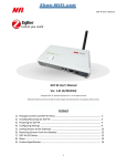
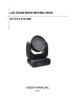
S05-LW User’s Manual S05-LW User’s Manual (ZigBee HA Profile) Ver. 1.01 Copyright 2011-14 Nietzsche Enterprise Co., Ltd. All rights reserved Nietzsche Enterprise reserves the right to make changes and improvements to its products without notice. Contact Information: Email: [email protected], Website: www.nhr.com.tw Content 1) 2) 3) 4) 5) 6) 7) 8) 9) Package Content and S05-LW Views. …...…….………...…………………………….……………... 2 Installing Mounting for S05-LW .………………………………………………………………………….. 3 Installing and Replacing Batteries in S05-LW ….....……………………………………………….. 4 Setting Transmission Interval for S05-LW ..….……………….………………………………….….. 5 Joining S05-LW to the Network ….………………………………….…………………………….……… 6 Removing S05-LW from the Parent’s Network ....………………………………………….…….. 6 S05-LW LED Status …..……………………………….…………………………………………………….……7 ZigBee Reset ..……………………………………………………………………………………………..……… 8 Product Specifications ………………………………………………………………………………………. 8 1 S05-LW User’s Manual Congratulations for choosing a world-class digital leaf wetness sensor using ZigBee wireless transmission technology. This manual is designed to help set up and get the most from the sensor in a few short minutes. Safety notice: Please read and follow the instructions before using this product To prevent electrical shock or fire, do not disassemble or expose the unit to liquids of any kind Only use attachments and / or accessories specified by the manufacturer 1 Package Content and S05-LW Views Mounting fixtures (mounting cradle, 2 wall plugs, 4 screws) NHR S05-LW digital leaf wetness sensor 4 x AA batteries If any of the above is missing please contact your supplier. Side Base Transmitter Internal Battery Product Serial Number Link Switch Compartment & Unique MAC Address Status LED Leaf Wetness Sensor 2 Transmission Interval Sensor Cable Setting Switches Connector S05-LW User’s Manual 2 Installing Mounting for S05-LW Requirements: Mounting fixtures Drill with 5mm (0.2 inches) drill bit size (if using wall plugs) or 3.5mm (0.14 inches) drill bit size (if not using wall plugs) Size 1 Phillips screwdriver a) Locate S05-LW with at least 15cm (approx.. 6 inches) spacing on each side (except on mounting side) avoiding the following sources of interference: direct sunlight, air flow from vents, fans, doors, windows, heaters, sources of steam, oil vapor, etc. b) If necessary, pre-drill mounting holes using mounting cradle for alignment, then use appropriate drill bit to drill the holes – 5mm (approx. 0.2 inches) if using wall plugs or 3.5mm (approx. 0.14 inches) if not using wall plugs. c) If necessary, insert wall plugs into the 4 holes and use size 1 Phillips screwdriver to fasten the screws securing the mounting cradle. Note: pay careful attention to the orientation of the mounting cradle. d) Install and remove S05-LW by placing it into and lifting it out of the cradle: Install - Remove 2 2 Initial hardware installation for S05-LW has been successfully completed. 3 S05-LW User’s Manual 3 Installing and Replacing Batteries in S05-LW Requirements: 4 x AA batteries a) Twist the base counter-clockwise to gain internal access to the transmitter, then pull the latch towards the hinge to open the battery compartment door: Battery Compartment Sensor Cable Connector Link Switch Note: When separating the base, be careful to ensure the sensor cable connector stays connected. b) If necessary, remove existing batteries. c) Install 4 x AA batteries into the battery compartment ensuring correct polarity, then close the compartment door and push the latch away from the hinge to secure the door in place. d) The status LED on S05-LW should start flashing to indicate its current state: Green LED Status 1 flash per second Ready to join a parent device 1 flash every 60 seconds Already joined a parent device and functioning normally 2 flashes every 5 seconds Already joined but unable find a parent device in the same network e) Replace the base by twisting it anti-clockwise until it is firmly secured to the transmitter. New batteries have been successfully installed. Recommendation: It is strongly recommended to install batteries into S05-LW just before joining to parent device as this will greatly improve battery life. For proper functioning of S05-LW and longer battery life, please install alkaline or lithium batteries from reputable suppliers. Low battery power is indicated by the red LED flashing once every 15 seconds. Replace batteries immediately to prevent potential damage and ensure proper functioning of S05-LW. 4 S05-LW User’s Manual 4 Setting Transmission Interval for S05-LW a) If necessary, remove the S05-LW from mounting cradle (see “Installing Mounting for S05-LW” section). b) Twist the base counter clockwise to gain internal access to the transmitter, being careful when separating the base to ensure the sensor cable connector stays connected. c) Set the transmission interval based on the following DIP switch positions: Transmit Interval DIP Switch Setting Transmit Interval 1 Second 1 Minute 5 Seconds 5 Minutes 10 Seconds 10 Minutes 15 Seconds 15 Minutes 20 Seconds 20 Minutes 25 Seconds 25 Minutes 30 Seconds 30 Minutes 35 Seconds 35 Minutes 40 Seconds 40 Minutes 45 Seconds 45 Minutes 50 Seconds 50 Minutes 55 Seconds 55 Minutes 60 Seconds 60 Minutes 65 Seconds 65 Minutes 70 Seconds 70 Minutes 75 Seconds 75 Minutes 5 DIP Switch Setting S05-LW User’s Manual d) Ensure S05-LW is joined to a parent device (see “Adding S05-LW to the Network” section). e) Use software for reading information from coordinator or gateway device (see relevant device’s manual) to confirm S05-LW transmissions are being received at the correct interval. f) Replace the base by twisting it anti-clockwise until it is firmly secured to the transmitter. g) If necessary, replace S05-LW into mounting cradle (see “Installing mounting for S05-LW” section). Transmission interval setting has been successfully configured. Note: Transmission interval is read at power on, a power cycle is required to effect interval change. 5 Joining S05-LW to the Network Requirements: Parent device, such as coordinator (eg. WZB-01USBC, WZB-02485C), gateway (eg. G07-W, WZB-05ET), or router (eg. WZB-01USBR, WZB-02485R) Sharp pointed tool a) Ensure parent device is powered on (see relevant device’s manual). b) Power on S05-LW (see “Installing and Replacing Batteries in S05-LW” section) ensuring it is in ready to join status (green LED flash once every second). c) Enable permit join status on parent device (see relevant device’s manual) and check S05-LW joined the parent device. d) If S05-LW has successfully joined the parent device, the green LED should flash 3 times, then once every 60 seconds. If S05-LW’s green LED does not flash once every 60 seconds, then it has not successfully joined. Repeat above steps until S05-LW has joined successfully. If S05-LW has still not joined after a few attempts, check it is within the operational range of 500m (line of sight) from the parent device and away from other 2.4GHz devices that might interfere with its operations. If S05-LW has joined successfully, but is showing disconnected status (green LED flashes twice every 5 seconds), then check parent device is correctly powered on. If the parent device is functioning correctly, S05-LW may be out of range or experiencing interference, additional router(s) may need to be added to ensure good connections. 6 Removing S05-LW from the Parent’s Network Requirements: 6 S05-LW User’s Manual Sharp pointed tool a) Ensure parent device (coordinator, gateway, or router) is powered on (see relevant device’s manual). b) Ensure S05-LW is powered on (see “Installing and Replacing Batteries in S05-LW” section) and has already joined the parent’s network (green LED flash once every 60 seconds). c) Twist the base counter clockwise to gain internal access to the transmitter, being careful when separating the base to ensure the sensor cable connector stays connected. d) Use a sharp pointed tool to apply 3 quick presses to the link switch on S05-LW, the red LED will flash rapidly for up to 30 seconds or until successful removal. e) If S05-LW has been successfully removed, the green LED should show ready to join status (flash once every second). Recommendation: It is strongly recommended to remove the batteries immediately from S05-LW once it has been removed from the parent’s network as this will prevent damage and greatly improve battery life. 7 S05-LW LED Status The S05-LW LED can be seen through the translucent base. The table below shows the LED status for S05-LW: S05-LW LED Green LED: Status 1 flash every second Ready to join – ready to join network of parent device (coordinator, gateway, or router) Green LED: Successfully joined – joined network of parent device 3 flashes (one time) Green LED: 1 flash every 60 seconds Green LED: 2 flashes every 5 seconds Red LED: Rapid Flashing up to 30 seconds Red LED: 1 flash every 15 seconds Green & Red LED: ON Normal Operations – joined network of parent device and functioning normally Disconnected – joined network, but unable to find any parent device of the network Removing – being removed from the network of the parent device Low Power – low battery power, replace batteries immediately ZigBee Reset – reset to factory default, remove all ZigBee network linkages 7 S05-LW User’s Manual 8 ZigBee Reset In the case where the parent devices (coordinator, gateway, or router) for S05-LW are no longer available or have been reset, S05-LW will need to be reset by applying a 5-second press to the link switch, the green & red LEDs will both come on during the reset, then the green LED should show ready to join status (flash once every second). Recommendation: It is strongly recommended to remove the batteries immediately from S05-LW once it has been reset as this will prevent damage and greatly improve battery life. 9 Product Specifications Measuring Element Leaf wetness sensor Wireless Protocol Compliant IEEE 802.15.4, ZigBee2007 / PRO HA Profile Operating Frequency 2.4GHz ISM band Transmission Range 500m (1640ft) line of sight RF Output Power 18dBm Power Supply DC 6 V 4 x AA alkaline batteries Operating Environment -40 ~ +125°C, < 85% relative humidity Power Consumption TX: 200mA, Sleep: 6µA Measurement Accuracy Temperature: ±0.5°C, Humidity: ±4.5% Network Topology Star / Tree / Mesh Transmit Interval 1 second to 75 minutes, based on DIP switch setting Battery Life > 1 year @ 10-minute transmission interval (dependent on battery quality) Enabling Devices Coordinator WZB-01USBC / WZB-02485C Gateway G07-W / WZB-05ET Router S05-R / WZB-01USBR / WZB-02485R Dimensions 130 (H) x 50 (Φ) mm / 5.1 (H) x 1.9 (Φ) inches Weight 142.8g / 5.04oz Supported Systems Windows NT ~ Win 8 Certifications CE / FCC 8