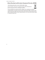
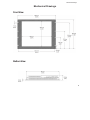
1
19” RACK MOUNT INDUSTRIAL MONITOR
USER MANUAL
Model: HRM819TR
i-Tech Company LLC
TOLL FREE: (888) 483-2418
email: [email protected]
web: www.iTechLCD.com
Table of Contents
Safety and Regulatory Information ................................................................................... 3
FCC Notice ........................................................................................................................................... 3
Waste Electrical and Electronic Equipment Directive (WEEE).............................................................. 4
Mechanical Drawings ....................................................................................................... 5
Front View ............................................................................................................................................ 5
Bottom View ......................................................................................................................................... 5
Side View.............................................................................................................................................. 6
Installation Instructions ................................................................................................... 7
Step 1: Prepare for Installation ............................................................................................................. 7
Step 2: Bench-test Confguration........................................................................................................... 8
Install Touchscreen Driver................................................................................................................. 9
Step 3: Install into Rack ...................................................................................................................... 11
Video Settings ................................................................................................................ 12
Setting the Timing Mode ..................................................................................................................... 12
Control Panel Buttons ......................................................................................................................... 13
OSD and Power Lock Settings ........................................................................................................... 14
On-Screen Display (OSD) Menus ....................................................................................................... 15
Auto Image Adjust Menu ................................................................................................................ 15
Contrast / Brightness Menu ............................................................................................................ 16
Input Select Menu .......................................................................................................................... 16
Color Adjust Menu .......................................................................................................................... 16
Information Menu ........................................................................................................................... 17
Manual Image Adjust Menu............................................................................................................. 18
Setup Menu .................................................................................................................................... 19
Cleaning Instructions...................................................................................................... 20
Glass, Acrylic, and Touchscreen Window Models .............................................................................. 20
No Protective Wndow (LCD Surface) Models ..................................................................................... 20
Troubleshooting ............................................................................................................. 21
Video Troubleshooting ........................................................................................................................ 21
Touchscreen Troubleshooting ............................................................................................................ 23
Specifcations ................................................................................................................. 24
Display ................................................................................................................................................ 24
Environmental .................................................................................................................................... 24
Video .................................................................................................................................................. 25
Electrical ............................................................................................................................................. 25
Functional ........................................................................................................................................... 25
Rack Compatibility .............................................................................................................................. 26
Physical .............................................................................................................................................. 26
Compliances and Certifcations ........................................................................................................... 26
2
Safety and Regulatory Information
Safety and Regulatory Information
WARNING!
To prevent fire or shock hazard, do not expose the unit to rain or moisture.
Dangerously high voltages are present inside the unit. Do not disassemble the unit.
Refer servicing to qualifed personnel only.
This equipment is not intended for use in critical applications where its failure to
operate would create immediate life threatening circumstances. Applications including,
but not limited to, nuclear reactor control, aerospace navigation systems and life
support systems are not appropriate for this product.
To be covered by UL 60950 3rd Edition, the socket-outlet shall be installed near the
equipment and shall be easily accessible.
FCC Notice
This equipment has been tested and found to comply with the limits for a Class A digital
device, pursuant to Part 15 of the FCC Rules. These limits are designed to provide
reasonable protection against harmful interference when the equipment is operated in a
commercial environment. This equipment generates, uses, and can radiate radio frequency
energy and, if not installed and used in accordance with the instruction manual, may cause
harmful interference to radio communications. Operation of this equipment in a residential
area is likely to cause harmful interference in which case the user will be required to correct
the interference at his own expense. Any changes or modifcations not expressly approved by
the grantee of this device could void the user’s authority to operate the device.
3
Safety and Regulatory Information
Waste Electrical and Electronic Equipment Directive (WEEE)
The following information is only for EU-member states:
The mark shown to the right is in compliance with the Waste Electrical and
Electronic Equipment Directive 2002/96/EC (WEEE).
The mark indicates the requirement NOT to dispose of the equipment as unsorted
municipal waste, but use the return and collection systems according to local law. Users
should contact their supplier and check the terms and conditions of the purchase contract.
When purchased directly from Hope Industrial Systems, you may contact technical support
for disposal arrangements.
4
Mechanical Drawings
Mechanical Drawings
Front View
Bottom View
5
Mechanical Drawings
Side View
6
Installation Instructions
Installation Instructions
Step 1: Prepare for Installation
IMPORTANT!
Perform the following steps BEFORE installation of the monitor into the rack.
1.
Ensure that suffcient power is available.
2.
Ensure that suffcient space is available to allow for proper air fow into and out of the
unit.
3.
Ensure that the air temperature around the unit (top and bottom) will not exceed the
rated specifcations of the unit.
The maximum rated temperature for the HRM819TR is 50°C (122°F).
► Remember that heat rises - the temperature at the top of the
cabinet will be much hotter than at the bottom if air inside the
enclosure is not actively circulating. Even in a sealed enclosure,
use of a circulation fan can greatly reduce temperature.
► Also,
remember that even though this product is designed to
operate at 50°C, the life span of any electronic device is shortened
when it is consistently operated at high temperatures. Therefore,
it is wise to take steps to keep the temperature of the ambient air
around the unit as low as possible.
4.
Ensure that the ambient humidity of the air around the unit does not exceed the
specifcations of the unit.
►
The maximum rated
is 90% non-condensing.
humidity
for
the
HRM819TR
7
Installation Instructions
Step 2: Bench-test Confguration
Make sure everything works before installing into the production environment.
TIP!
If using a KVM extender, please refer to the installation instructions included with the
KVM extender module. It is particularly important to bench-test the full confguration
prior to final installation. This will help to identify and troubleshoot any system issues
while confguration changes may still be easily made.
Install Cable Connections
All monitors are shipped with both a 6 ft. VGA video cable and 6 ft. power cable, unless longer
cables were ordered in their place. If you ordered a touchscreen monitor, you also received a 6
ft. Serial (RS-232) cable and 6 ft. USB cable.
The cable ports are located on the rear of the monitor. Refer to the following diagram and
instructions to connect power, video, and touchscreen (if applicable) to your monitor.
Video Connection
The HRM819TR supports analog and digital video.
Analog Video Connection
Connect one end of the VGA video cable to the HD-15 input port on the rear of the
monitor. Connect the other end to the analog video output port on the host computer.
8
Installation Instructions
Digital Video Connection
Connect one end of the DVI video cable to the DVI-D input port on the rear of the
monitor. Connect the other end to the digital video output port on the host computer.
Power Connection
The HRM819TR is powered by 120/240 VAC, 1.5/0.75 A, 60/50 Hz.
Connect the AC power cable to the power input port on the rear of the monitor. Connect the other
end into a nearby outlet.
Install Touchscreen Driver
Applies to touchscreen monitors only. Instructions below apply to Windows systems. Both Serial
and USB ports are present on all touchscreen monitors, but only one should be used to connect
the touchscreen interface to the monitor.
All touchscreen monitors are shipped with a CD-ROM that contains documentation and drivers for
all major operating systems. To be sure that you have the most current information, please check
the following Internet address:
http://www.i-techcompany.com/support-top.html
IMPORTANT!
If you will be using a Serial connection, connect the Serial cable frst, and then
install the touchscreen driver. If you will be using a USB connection, install the
touchscreen driver frst, and then connect the USB cable.
Serial (RS-232) Connection
1.
Connect one end of the Serial cable to the Serial input port on the rear of the
monitor. Connect the other end to the Serial port on the host computer. Tighten the
captive screws on the cable connectors to ensure adequate strain relief.
9
Installation Instructions
2.
Select the appropriate driver for your operating system.
a. If downloading from the web address listed above, select the appropriate
driver for your operating system.
b.
If using the included CD, insert it into the host computer's CD-ROM drive. If
the CD does not automatically run, browse the contents of the CD and open
the ReadMe.htm fle in a web browser. Select the appropriate driver.
NOTE: For Windows 7 and Vista operating systems, you must save the driver to
a location on your hard drive, then run using elevated privileges by right-clicking
on the fle and selecting "Run as administrator".
3.
Click to "Run" the software when prompted. Follow on-screen instructions to
download and execute the touchscreen driver installation.
USB Connection
1.
Select the appropriate driver for your operating system.
a. If downloading from the web address listed above, select the appropriate
driver for your operating system.
b.
If using the included CD, insert it into the host computer's CD-ROM drive. If
the CD does not automatically run, browse the contents of the CD and open
the ReadMe.htm fle in a web browser. Select the appropriate driver.
NOTE: For Windows 7 and Vista operating systems, you must save the driver to
a location on your hard drive, then run using elevated privileges by right-clicking
on the fle and selecting "Run as administrator".
2. Click to "Run" the software when prompted. Follow on-screen instructions to
download and execute the touchscreen driver installation.
3. A cable retention bracket comes installed on the USB port on the rear of the monitor and
will help to secure the cable and ensure adequate strain relief. Route one end of the USB
cable through the retention bracket and connect it to the USB input port on the monitor.
Connect the other end to the USB port on the host computer.
Calibrate the Touchscreen
Once the driver has fnished installing, you are ready to calibrate the touchscreen. Open the
touchscreen's Control Panel, located in the host computer's Control Panel.
NOTE: The latest versions of Wndows touchscreen drivers provided by Hope Industrial have an
"Enhanced Calibration Mode" option. If applicable to your particular driver, this setting may be
found in the touchscreen's Control Panel under the "Mode" tab.
10
Installation Instructions
Step 3: Install into Rack
Once you have completed the full bench-test confguration and confrmed that all components are
working properly, you are ready to install the monitor into the rack.
Hope Industrial Systems' Rack Mount monitors conform to the Electronic Industries Association
standard EIA-310-D. Our monitors will ft in type A, B, and C racks with a width of 482.6 mm (19")
(preferred EIA rack width).
WARNING!
i-Tech will not assume liability for damage to internal electronics due to
improper installation. Contact HIS if you need additional assistance.
The HRM819TR has a panel height of 8U (shown below).
0"
37.5
mm
(1.48")
316.9
mm
139.1 mm
(5.48")
(12.48"
215.3 mm
(8.48"
354.3
mm
(13.95")
8U
(13.95”)
Video Settings
Video Settings
Setting the Timing Mode
Setting the timing mode of your computer graphics adapter (or other video source) is important
for maximizing the quality of the screen image and for minimizing eye strain. The timing mode
consists of the resolution (e.g. 1280 x 1024) and refresh rate (or vertical frequency; e.g. 60 Hz).
After setting the timing mode, use the On-Screen Display (OSD) controls to adjust the screen
image.
TIP!
For the best picture quality, set your computer graphics adapter timing mode to:
VESA 1280 x 1024 @ 60 Hz
Please refer to the computer graphics adapter manufacturer's manual for instructions on setting
the resolution and timing mode. In Microsoft Windows, these settings may be found at the
following location:
► ME, 2000, XP: Control Panel > Display > Settings
► Vista: Control Panel > Personalization > Display Settings
► Windows 7: Control Panel
Adjust Screen Resolution
> Appearance and Personalization
>
WARNING!
Do not set the graphics card in your computer to exceed the maximum refresh rate
of 75 Hz; doing so may result in permanent damage to your display.
12
Video Settings
Control Panel Buttons
Use the control panel buttons located on the back of the monitor to display and adjust various
settings on the On-Screen Display (OSD) menu.
1.
To display the Main Menu, press button [1].
NOTE: All OSD menus and adjustments screens disappear automatically after
15 seconds. This is adjustable through the OSD Time Out setting in the Setup
menu.
2.
To select a control to adjust, press the up [▲] or down [▼] button to scroll through the
menu.
3.
Press button [2] to open the menu for a selected control.
4.
To adjust the control, press the up [▲] or down [▼] button.
5.
To save the adjustments and return to the main OSD menu, press button [1] once. To
exit the OSD menu, press button [1] twice.
13
Video Settings
.
OSD and Power Lock Settings
► OSD Lock: Press and hold [1] and the up [▲] button for 10 seconds. If any buttons are
pressed the message OSD Locked will display for 3 seconds.
► OSD Unlock: Press and hold [1] and the up [▲] button again for 10 seconds.
► Power Button Lock: Press and hold [1] and the down [▼] button for 10 seconds. If the
power button is pressed, the message Power Button Locked will display for 3 seconds.
With or without this setting, after a power failure, your monitor's power will automatically
turn ON when power is restored.
► Power Button Unlock: Press and hold [1] and the down [▼] button again for 10
seconds.
14
Video Settings
On-Screen Display (OSD) Menus
To open the OSD menu, press button [1] once. The following screen will appear:
Main Menu
Description
Auto Image Adjust
Automatically sizes, centers, and fne tunes the video signal to
eliminate waviness and distortion.
Contrast / Brightness
Includes the Contrast and Brightness functions.
Input Select
Allows the user to toggle between inputs.
Color Adjust
Provides several color adjustment modes.
Information
Displays the timing mode (video signal input).
Manual Image Adjust
Includes the H./V. Position, Horizontal Size, Fine Tune,
Sharpness, Dynamic Contrast, and ECO Mode functions.
Setup Menu
Includes the Language Select, Resolution Notice, OSD Position,
OSD Time Out, OSD Background, and Auto Power Off functions.
Memory Recall
Returns adjustments back to factory settings.
Auto Image Adjust Menu
The Auto Image Adjust menu automatically sizes, centers, and fne tunes the video signal to
eliminate waviness and distortion.
NOTE: Auto Image Adjust works with most common video cards. If this function does not work on
your display, lower the video refresh rate to 60 Hz and set the resolution to its pre-set value.
15
Video Settings
Contrast/ Brightness Menu
The Contrast/Brightness menu includes the Contrast and Brightness functions.
Contrast / Brightness
Menu
Description
Contrast
•
•
Brightness
•
•
Adjusts the difference between the image background
(black level) and the foreground (white level).
This feature may also be accessed by pressing the up [▲]
button outside of the OSD menu.
Adjusts the background black level of the screen image.
This feature may also be accessed by pressing the down
[▼] button outside of the OSD menu.
Input Select Menu
The Input Select menu allows the user to toggle between inputs if there is more than one
computer connected to the display.
Color Adjust Menu
The Color Adjust menu provides several color adjustment modes, including preset color
temperatures and a User Color mode which allows independent adjustment of red (R), green (G),
and blue (B). The factory setting for this product is 6500K (6500 Kelvin).
16
Video Settings
Color Adjust Menu
Description
sRGB
This is quickly becoming the industry standard for color
management, with support being included in many of the latest
applications. Enabling this setting allows the LCD to more
accurately display colors the way they were originally intended.
NOTE: Enabling the sRGB setting will cause the Contrast and
Brightness adjustments to be disabled.
9300K
Adds blue to the screen image for cooler white (used in most
offce settings with fuorescent lighting).
7500K
Adds blue to the screen image for cooler white (used in most
offce settings with fuorescent lighting).
6500K
Adds red to the screen image for warmer white and richer red.
5000K
Adds green to the screen image for a daylight color.
User Color
Individual adjustments for red (R), green (G), and blue (B).
1.
To select color (R, G, or B) press button [2].
2.
To adjust selected color, press the up [▲] or down [▼]
button.
NOTE: If you select RECALL from the OSD Main Menu when
the product is set to a Preset Timing Mode, colors return to the
6500K factory preset.
Information Menu
The Information menu displays the timing mode (video signal input) coming from the graphics card
in the computer. See your graphics card's user guide for instructions on changing the resolution
and refresh rate (vertical frequency).
NOTE: VESA 1280 x 1024 @ 60 Hz (recommended) means that the resolution is 1280 x 1024
and the refresh rate is 60 Hz.
17
Video Settings
Manual Image Adjust Menu
The Manual Image Adjust menu includes the H./V. Position, Horizontal Size, Fine Tune,
Sharpness, Dynamic Contrast, and ECO Mode functions.
Manual Image Adjust
Menu
Description
H./V. Position
(Horizontal / Vertical
Position)
Moves the screen image left or right and up or down.
Horizontal Size
Adjusts the width of the screen image.
Fine Tune
Sharpens the focus by aligning text and/or graphics with pixel
boundaries.
NOTE: Try the Auto Image Adjust function frst.
Sharpness
Adjusts the clarity and focus of the screen image.
Dynamic Contrast
Allows the user to turn the contrast ratio enhancement On or
Off. Dynamic Contrast adjusts the brightness of the backlights
to improve the contrast of the screen image (darker screen
images will have better black levels).
ECO Mode
Provides lower power consumption by reducing the brightness.
18
•
Standard is the default brightness setting
•
Optimize reduces brightness by 25%
•
Conserve reduces brightness by 50%
Video Settings
Setup Menu
The Setup menu includes the Language Select, Resolution Notice, OSD Position, OSD Time Out,
OSD Background, and Auto Power Off functions.
Setup Menu
Description
Language Select
Allows the user to choose the language used in the menus and
control screens.
Resolution Notice
Advises the optimal resolution to use.
OSD Position
Allows the user to move the OSD menus and control screens.
OSD Time Out
Sets the length of time the OSD screen is displayed. For
example, with a "15 second" time setting, if a control is not
pushed within 15 seconds, the display screen disappears.
OSD Background
Allows the user to turn the OSD background On or Off.
Auto Power Off
When enabled, this setting will automatically power off the
monitor when no signal is detected for 3 minutes.
Memory Recall Menu
The Memory Recall menu returns adjustments back to factory settings.
NOTE: This control does not affect changes made with the Language Select or Power Lock
settings.
19
Cleaning Instructions
Cleaning Instructions
CAUTION!
DO NOT USE ABRASIVE MATERIALS, SUCH AS PAPER TOWELS OR DIRTY SHOP
RAGS, ON THE DISPLAY AS IT WILL SCRATCH THE PROTECTIVE COATING.
ALWAYS USE A SOFT CLOTH, PREFERABLY MADE OF COTTON.
IMPORTANT!
Always spray the cleaner on the cloth or towel frst and then clean the monitor
screen. Cleaner sprayed directly on the monitor could possibly leak inside a
non-sealed unit and cause damage.
Glass, Acrylic, and Touchscreen Window Models
All displays with safety glass, acrylic, or resistive touchscreen windows may be cleaned using any
standard glass cleaner as long as there is no abrasive or oily content. Vinegar or ammonia will
not hurt the screen.
The anti-refective coatings on glass window-equipped displays are physically part of the surface of
the glass and resist degradation to the Military Specifcations.
To minimize over-run of cleaning solution, spray the cloth frst and then clean the screen.
No Protective Window (LCD Surface) Models
Wipe the screen with a clean, soft, lint-free cloth. This will remove dust and other particles. If the
screen is still not clean, apply a small amount of non-ammonia, non-alcohol based glass cleaner
onto a clean, soft, lint-free cloth, then wipe the screen.
20
Troubleshooting
Troubleshooting
Video Troubleshooting
IMPORTANT!
If using a KVM extender, first try to resolve any problems using the solutions listed
below. If the problem still exists, try bypassing the KVM extender. If this fixes the
problem and allows the monitor to work properly, then the KVM extender is the
source of the problem. Please refer to the troubleshooting section of the KVM
extender manual or contact i-Tech for additional assistance.
Symptom
Causes
Solutions
No image on the
screen and
control's Power
Indicator light is
not lit
Monitor is not powered on.
•
Press the Power button on the
monitor and make sure the Power
Indicator light is lit blue.
•
Check power connections at the
monitor and power source.
"No Signal"
Video cable is not plugged in
message box and correctly.
no image on the
PC is in Power Saving
screen
mode.
No image on the
screen and
control's Power
Indicator light is
lit orange
Check the video cable connection at the
monitor, PC, and/or KVM extender.
Power Saving mode can usually be exited
by moving the mouse.
PC is not powered on.
Ensure PC is powered on.
PC is not sending signal.
Connect the PC to another known working
monitor to check the PC source signal.
Video cable is not plugged in
correctly.
Check the video cable connection at the
monitor, PC, and/or KVM extender.
PC is in Power Saving
mode.
Power Saving mode can usually be exited
by moving the mouse.
PC is not powered on.
Ensure PC is powered on.
PC is not sending signal.
Connect the PC to another known working
monitor to check the PC source signal.
21
Troubleshooting
Symptom
Causes
"Out of Range"
message box and
no image on the
screen
The source signal exceeds the Adjust the computer settings to the
maximum resolution and/or
monitor's native resolution:
1280 x 1024 @ 60 Hz
refresh rate that the monitor
can handle ( > 1280 x 1024
resolution or > 75 Hz refresh
rate).
Incorrectly
displayed or
partial image on
the screen
Monitor has not been
adjusted correctly for the
source signal.
Wrong or
abnormal colors
(white is not
white)
Monitor color settings are
incorrectly adjusted.
Reset the monitor to the factory default
settings by activating the "Memory Recall"
function in the OSD.
Video cable is not securely
connected.
If any colors (red, green, or blue) are
missing, check the video cable to make
sure it is securely connected.
Video cable is bad.
Check to make sure there are no loose or
broken pins in the cable connector.
Shorts in the cable could also cause an
improper image to display.
Screen image is
dim
Brightness and/or contrast
settings are not set properly.
Adjust the monitor's brightness and
contrast settings in the OSD's "Contrast/
Brightness" menu.
The message
"OSD Locked"
appears
The OSD has been locked to
prevent unauthorized
changes to display settings.
Press and hold [1] and the up [▲] button
for 10 seconds.
The message
"Power Button
Locked"
appears
The Power button has been
locked to prevent
unauthorized shut down of
the monitor.
Press and hold [1] and the down [▼]
button for 10 seconds.
22
Solutions
•
Activate the "Auto Image Adjust"
function in the OSD menu.
•
Fine tune the picture by manually
adjusting the image. In the OSD
menu, these functions can be found in
the "Manual Image Adjust" menu.
Troubleshooting
Touchscreen Troubleshooting
Applies to touchscreen monitors only. To be sure that you have the most current driver, please
check the following Internet address:
http://www.i-techcompany.com/support-top.html
Symptom
Causes
Solutions
No response
when touching
the touchscreen
Touchscreen driver has not
been installed.
Download and install the latest driver from
the i-Tech website.
Touchscreen cable is not
plugged in correctly.
Make sure either the USB or Serial cable is
securely connected to the monitor and PC.
Do not connect both.
If using a USB connection,
does the USB cable length
exceed 3 meters?
USB cables have a 3 meter limitation and
could cause no touch response if this is
exceeded.
If using a Serial connection,
is the Serial cable plugged
into the correct COM port?
Ensure that the Serial cable is connected
to the COM port being used prior to
installing the touchscreen driver.
Touchscreen driver has not
been installed.
Download and install the latest driver from
the i-Tech website.
Touchscreen has not been
calibrated.
Activate the calibration utility. In Windows
systems, these settings may be found at
the following location:
Control Panel > Elo Touchscreen >
"General" Tab
• Press the Align button.
• Touch all targets as the appear to
calibrate the touchscreen.
• Press the Green Check button when
verifed.
The cursor
moves but does
not follow my
finger when
touching the
touchscreen
23
Specifcations
Specifcations
Display
Type
Thin-flm transistor (TFT) Active Matrix Liquid Crystal
Size
19" diagonal
Image Size (W x H)
376 mm x 301 mm (14.8" x 11.9")
Native Resolution
SXGA (1280 x 1024, 5:4 aspect ratio)
Minimum Resolution
VGA (640 x 480)
Pixel Pitch
0.294 mm x 0.294 mm
Number of Colors
16.7 million
Brightness (white)
250 nits (cd/m2)
Viewing Angle (Hori/Vert)
170° / 160°
Contrast Ratio (typical)
1000:1 (static); 100,000:1 (dynamic)
Backlight
Two CCFTs (Cold Cathode Fluorescent Tube); 50,000 hour
brightness half-life; replaceable
Environmental
Temperature
0° to 50°C (32° to 122°F)
Humidity
20% to 90% non-condensing
Operating Shock
15 g, 6 msec, half-sine
Operating Vibration (sine)
Transport Vibration
(random)
Altitude
24
1.0g, swept sine 9 - 500 Hz
0.1g2 / Hz, 10 - 200 Hz
0.03g2 / Hz, 200 - 2000 Hz
•
Operating: up to 10,000 feet
•
Non-operating: up to 40,000 feet
Specifcations
Video
Input Connectors
HD-15, DVI-D
NOTE: Optional BNC input using HD-15 to 5-wire BNC adapter;
see "Input Signal Formats" for a list of compatible video signals.
Input Signal Formats
•
RGB Analog video, 0.7/1.0 Vp-p, 75 Ohms
Compatible sync modes: Separate H/V sync
•
DVI
NOTE: NTSC/PAL composite input available (call for details)
Horizontal Scan
30 – 82 kHz
Vertical Scan
Supported Video
Standards
56 – 75 Hz
Response Rate (typical)
•
1280 x 1024 @ 60, 75 Hz
•
1280 x 960 @ 60, 75 Hz
•
1024 x 768 @ 60, 70, 72, 75 Hz
•
800 x 600 @ 56, 60, 72, 75 Hz
•
720 x 400 @ 70 Hz
•
640 x 480 @ 60, 75 Hz
5 ms
Electrical
Monitor Input
120/240 VAC, 1.5/0.75 A, 60/50 Hz
Power Consumption
~ 25 W
Power Consumption
(Standby mode)
<1W
Functional
Control Panel Buttons
1 (Menu), 2 (Enter), Power, Down, Up
On-Screen Display (OSD)
Menus
Touchscreen Option
Auto Image Adjust, Contrast / Brightness, Input Select, Color
Adjust, Information, Manual Image Adjust, Setup, Memory Recall
5-wire resistive system; emulates a mouse; Serial (RS-232) and
USB interface to host computer
25
Specifcations
Rack Compatibility
EIA Standard
EIA-310-D
EIA Type Rack
A, B, and C
Rack Width
482.6 mm (19.0") (preferred EIA width)
Mounting
8 Slots, 7.1 mm (0.28") wide
Panel Height
8U, 354.3 mm (13.95")
Physical
Enclosure Type
Rack mount
Panel Rating
Built to IP20 standards; NEMA/UL Type 1
Bezel Finish
Black Powder-Coated Carbon Steel, matte fnish
Depth Behind Bezel
57.9 mm (2.28")
Front Bezel Outside
Dimensions (W x H x D)
Net Weight
482.6 mm x 354.3 mm x 3.2 mm (19.0" x 13.95" x 0.125")
Shipping Weight
19 lbs.
15 lbs.
Compliances and Certifcations
Electrical
Environmental
Enclosure
26
•
UL 60950 3rd Edition / cUL Recognized Component (File No.
E212889)
•
UL 508A Listed (File No. E318630)
•
FCC Class A
•
CE
•
RoHS (Hazardous Substances)
•
IEC 60721-3 (Reliability)
•
WEEE (Registration No. WEE/DJ1859ZX for UK only)
UL 50E (File No. E318630)