1
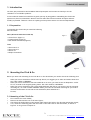
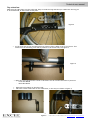
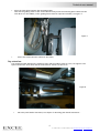
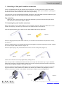
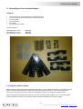
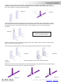
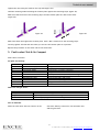
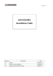
Technical Manual
Excel
Click & Go ‘Compact’
Read instructions before use
Technical user manual
Contents
1. Introduction ...................................................................................... 2
1.1 Preparation...................................................................................... 2
2. Mounting the Click & Go ........................................................................ 2
2.1 Mounting of the Click & Go ................................................................... 2
3. Mounting of the push handles extensions .................................................... 5
3.1 Mounting the push handles extensions ...................................................... 5
4. Mounting universal mountingset............................................................... 6
4.2 Adjusting fixation plates ...................................................................... 6
5. Fault codes Click & Go Compact .............................................................. 8
6. Tuning the hand controller..................................................................... 9
1
© 2009 VAN OS MEDICAL UK LTD.
Tel. +44(0)1757 701177, Fax +44(0)1757 706011, E-mail: [email protected], www.vanosmedical.com
Technical user manual
1. Introduction
You have just purchased a Van Os Medical UK Ltd powerpack and we want to thank you for the
confidence in our EXCEL® products.
In this technical manual we would like to guide you step by step guide in assembling the Click & Go
system on a (Excel ®) wheelchair. We have tried to make this technical manual as simple and userfriendly as possible. However if there is anything unclear please contact our technical department.
1.1 Preparation
To assemble the Click & Go you need the following
Parts and tools:
Parts (delivered with the Click & Go)
Figure 1
• Control lever (Figure 1)
• Fixation plates (Figure 2)
• Push handle extensions(Figure 3)
Tools
•
•
•
•
Allen wrench 4
Allen wrench 5
Wrench 10
Phillips Screwdriver
Figure 2
Figure 3
2. Mounting the Click & Go
Before you start with mounting of the Click & Go on the wheelchair you need to check the following first:
-
When you have a wheelchair without anti-tip wheels, we suggest you to order and mount these first.
Our order number is 92000012.
When you have a wheelchair with seat width 50 cm or more, you need to use an adaptation set 50 –
55 cm, in stead of the original guiding frame. Our order number is 08100330.
When you have a wheelchair with a seat height different than 50 cm, you need to use the universal
mounting set, our order number 08100302. When you order the universal mounting set you need to
mention the diameter of the tube of the wheelchair (Excel wheelchair =
25 mm).
2.1 Mounting of the Click & Go
•
•
•
•
First remove the crutch holder;
Remove the bolt and the nut of the Anti-Tipper;
Check that the drilled holes in the fixation plate match the holes in the (Excel®) wheelchair frame;
If so, mount the mounting plate with the bolts on the side frame of the wheelchair, as shown in
Figure 4. If not go first to Chapter 4.
2
© 2009 VAN OS MEDICAL UK LTD.
Tel. +44(0)1757 701177, Fax +44(0)1757 706011, E-mail: [email protected], www.vanosmedical.com
Technical user manual
Pay attention:
Make sure the right plate is at the right side. Keep in mind the long and short pin. Make sure the long pin
is at the backside, at the bottom of the plate.
Figure 4
At the front side of the mounting plate you need to place rubber rings of circa 4 mm. This
makes sure the mounting plate will be parallel to the frame tube, see figure 5.
•
Figure 5
• Make sure you use bolts with a sunk or flat head. You do not want the bolts to point out.
- Front side M6x40
- Back side M6x50
•
•
Repeat this procedure on the other side;
Place the crutch holder back on the wheelchair, in the way it is shown in figure 6;
3
Figure 6
© 2009 VAN OS MEDICAL UK LTD.
Tel. +44(0)1757 701177, Fax +44(0)1757 706011, E-mail: [email protected], www.vanosmedical.com
Technical user manual
Place the Click & Go between the mounting plates;
Slide out the guiding frame of the Click & Go until they touch the mounting plate. Make sure the
Click & Go is in the middle, so the guiding frame must be equal at both sides, see figure 7.
•
Figure 7
Secure the Click & Go with 4 bolts to the frame;
•
Pay attention:
The maximum width between the mounting plate and the guiding frame is 3 mm, see figure 8. The
space between the Click & Go and the floor must be around 1,5 until 2 cm.
Figure 8
•
Place the push handle extensions, see chapter 3 ‘Mounting push handle extensions’.
4
© 2009 VAN OS MEDICAL UK LTD.
Tel. +44(0)1757 701177, Fax +44(0)1757 706011, E-mail: [email protected], www.vanosmedical.com
Technical user manual
3. Mounting of the push handles extensions
There is a possibility that the push handles of the wheelchair, on which you want to place the Click &
Go, are too short to use in combination with the Click & Go system. When your attendant is pushing you
he will hit the Click & Go with his feet. This can be very annoying.
To prevent this you use the supplied push handle extensions. The push handle extensions makes sure your
attendant can push you with the Click & Go system without any problems.
Pay attention:
When you want a Click & Go with your Excel G4 wheelchair you need to drill out the push handle
with a bore of 18 mm until a depth of 48 mm.
3.1 Mounting the push handles extensions
Remove the rubber from the push handles of your wheelchair (figure 9). Most push handles have on the
inside a anti-slip layer, therefore you need to cut the rubber loose to remove them.
Take the supplied plastic plug. It with fit in the push handle tube exactly (figure 10).
Figure 9
Figure 10
Place the plug against the push handle extension, on the side with the smallest hole(side that is weld),
see figure 11.
Place the supplied bolt in the push handle extension and tighten the plastic plug with your hands against
the end of the push handle extension (figure 12).
Place the plastic plug in the push handle tube and turn the bolt firmly down (figure 13).
Figure 12
Figure 11
Figure 13
Check if the extension is securely tightened by making lateral movements with it.
After this you need to assembly the hand controller in the right and the easiest way for your attendant.
Please pay attention to the push handle extension when you are placing the hand controller (figure 14).
Use one of the supplied fillings for the hand controller.
Place the supplied extended push handle rubbers over the push handle extensions (figure 15). The best
way to do this is to rub the inside of the rubbers with benzine, the rubbers will glide gently over the
tubes. As soon as the benzine in the rubbers is dried up the rubbers are securely tightened.
Figure 14
Figure 15
5
© 2009 VAN OS MEDICAL UK LTD.
Tel. +44(0)1757 701177, Fax +44(0)1757 706011, E-mail: [email protected], www.vanosmedical.com
Technical user manual
4. Mounting universal mountingset
Content:
•
•
•
•
•
•
4x
8x
4x
8x
8x
8x
16 holes plate, for mounting of the mounting plates
tube clamp, (tube diameter that is mention by you)
cover plate
tap ends M6
nut M6
self-locking bolt M6
Our ordernumber:
Tube diameter 19 mm
Tube diameter 22 mm
Tube diameter 25 mm
: 93810922
: 93810923
: 93810924
4.2 Adjusting fixation plates
When you have a wheelchair with a different seat height or from a different brand, is it possible that the
holes in the fixation plates don’t match the frame holes. When the holes in the fixation plates don’t
match the frame holes you have to follow the following procedure to install the fixation plates.
Take the supplied mounting strips from the universal mounting system (figure 16). The mounting strips
makes it possible to mount the Click & Go under wheelchairs outside of the Excel® range.
6
© 2009 VAN OS MEDICAL UK LTD.
Tel. +44(0)1757 701177, Fax +44(0)1757 706011, E-mail: [email protected], www.vanosmedical.com
Technical user manual
Assemble on both sides of the side frame of the wheelchair two mounting strips (figure 17). The two
mounting strips are meant to be universal adaptation plates to make sure the fixation plates of the Click
& Go can be adjust to the right height and distance.
Figure 16
Figure 17
Turn the supplied tap ends in the holes that are point out until the back side of the tap ends are equal
with the back site of the mounting strips (figure 18). Repeat this for the other strips. Make sure you use
the same holes for the tap ends on all the strips. This is important for the rest of the mounting
procedure.
Figure 18
On the heart line of the strips are 4 holes:
-
2 holes for the smaller clamp blocks
2 holes for the bigger clamp blocks
Place the contra nuts on the tap ends and tighten them down. Make sure the tap ends is equal with the
back of the mounting strip (figure 19).
Place one side the clamp blocks over the tap ends (figure 20) and repeat this for the second strip.
Figure 19
Figure 20
Hold the mounting strips including the clamp block against the side frame of the wheelchair
(figure 21).
Place the second side of the clamp block over the tap ends (figure 22) and place the cover plates against
the backside of the second side of the clamp block (figure 23).
Figure 21
Figure 22
Figure 23
7
© 2009 VAN OS MEDICAL UK LTD.
Tel. +44(0)1757 701177, Fax +44(0)1757 706011, E-mail: [email protected], www.vanosmedical.com
Technical user manual
Tighten the nuts with your hands on the tap ends (figure 24).
Hold the mounting model including the fixation plate against the mounting strips (figure 25).
Make sure that the holes of the mounting strips and the fixation plate are above each other
(figure 25).
Figure 24
Figure 25
Mark these holes and tighten the fixation plate with a M6 x 8 mm bolt to the mounting strips.
Securely tighten all bolts and nuts when you are sure the fixation plate is in position.
Repeat this procedure for the other side of the wheelchair.
5. Fault codes Click & Go Compact
With S-Drive controller
All lights are blinking:
Flash Code
1x
2x
3x
4x
5x
6x
7x
8x
9x
10x
Fault
Batteries are empty
Bad motor contact
Short circuit motor
Not in use
Not in use
Power failure
Potentiometer fault
Controller fault
Park / motor brake
Bad connection
Solution
Charge the batteries
Check the connector of the motor and the motor brushes
Check motor or replace controller
Charger in use
Check potentiometer (stand 0) and wiring
Check wiring and connectors, replace controller
Check motor brake and wiring
Check batteries, wiring and connectors
Charge the batteries
Check the connector of the motor and the motor brushes
When the red light blinks:
Flash code
Slowly
Every 5 seconds
Fast
Solution
Batteries needs to be charged.
Sleep mode, switch the Click & Go on again.
Check wiring or program the Click & Go again.
PAY ATTENTION:
When the Click & Go does not function at all:
Check the battery connection, the automatic fuse
and the glass fuse.
8
© 2009 VAN OS MEDICAL UK LTD.
Tel. +44(0)1757 701177, Fax +44(0)1757 706011, E-mail: [email protected], www.vanosmedical.com
Technical user manual
6. Tuning the hand controller
Loosen the hex screw on the back of the throttle. You can reach the hex screw through a hole on the
back side of the hand controller, see figure 26.
Figure 26
Tighten the set screw of the gas potentiometer as far back as possible against the clock. You can reach
the set screw trough the hole on the right side, see figure 27.
Figure 27
Securely tighten the hex screw and check the working of the Click & Go.
9
© 2009 VAN OS MEDICAL UK LTD.
Tel. +44(0)1757 701177, Fax +44(0)1757 706011, E-mail: [email protected], www.vanosmedical.com
www.vanosmedical.com