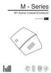
1
User Manual Excel Entice ‘Universe’ Read instructions before use Overall user manual Contents 1. INTRODUCTION .................................................................................................................................................................. 2 1.1 IMPORTANT SYMBOLS IN THIS MANUAL ............................................................................................................................................... 2 1.2 TYPE CLASSIFICATION AND AREA OF USE .............................................................................................................................................. 2 2. SAFETY NOTES .................................................................................................................................................................... 3 2.1 GENERAL SAFETY NOTES .................................................................................................................................................................. 3 2.2 SAFETY INFORMATION ON ELECTROMAGNETIC INTERFERENCE ................................................................................................................ 3 2.3 SAFETY INFORMATION ON DRIVING AND FREEWHEEL MODE .................................................................................................................. 4 3. THE MOST IMPORTANT PARTS ........................................................................................................................................... 5 4. DRIVING .............................................................................................................................................................................. 5 4.1 BEFORE DRIVING FOR THE FIRST TIME ................................................................................................................................................. 5 4.2 TAKING OBSTACLES ........................................................................................................................................................................ 5 4.3 DRIVING UP AND DOWN GRADIENTS ................................................................................................................................................... 6 4.4 PARKING AND STANDSTILL ............................................................................................................................................................... 6 5. PUSHING THE SCOOTER BY HAND ....................................................................................................................................... 6 5.1 DISENGAGING MOTORS................................................................................................................................................................... 7 6. THE CONTROL PANEL .......................................................................................................................................................... 7 6.1 CONTROL PANEL LAYOUT ................................................................................................................................................................. 7 6.2 DRIVING THE SCOOTER .................................................................................................................................................................... 8 6.3 DIAGNOSTICS AND TROUBLE SHOOTING.............................................................................................................................................. 8 7. ADJUSTMENT OPTIONS..................................................................................................................................................... 10 7.1 ADJUSTING THE ANGLE OF THE BACKREST .......................................................................................................................................... 10 7.2 ADJUSTING THE SEAT .................................................................................................................................................................... 10 7.3 ADJUSTING THE WIDTH OF THE ARMRESTS ......................................................................................................................................... 10 7.4 RELEASING THE SEAT SO THAT IT MAY ROTATED AND/OR REMOVED ........................................................................................................ 11 8. ELECTRICAL SYSTEM .......................................................................................................................................................... 11 8.1 ELECTRONICS PROTECTION SYSTEM ................................................................................................................................................. 11 8.2 BATTERIES .................................................................................................................................................................................. 12 9. CARE AND MAINTENANCE ................................................................................................................................................ 14 10. TECHNICAL SPECIFICATIONS ............................................................................................................................................. 15 © 2011 VAN OS MEDICAL UK LTD. Tel. +44(0)1757 701177, Fax +44(0)1757 706011, E-mail: [email protected], www.vanosmedical.com ~1~ Overall user manual 1. INTRODUCTION Dear User, First of all we wish to thank you for your confidence in our products! We hope you will enjoy your new Scooter. This manual contains important hints and information on: Safety Operation Care and maintenance. Please familiarise yourself thoroughly before making your first trip. Some of the necessary maintenance and adjustments can be carried out by the user. Some adjustments, however, require technical training and are only allowed to be performed by your Excel® specialised dealer. Any damage or defects caused by non observance of the operating instructions or by poor maintenance are excluded from liability. The instructions contain information which is protected by copyright. They may not be reproduced or copied in whole or in part without the prior written consent of Excel® or its authorised representative, Errors and modifications serving technological progress excepted. 1.1 Important symbols in this manual Note: This symbol indicates hints and suggestions which should help make operating the product easier and point out special functions. Warning: This symbol warns you of danger! Follow the instructions to avoid injury to the user or damage to the product! Requirements: This symbol indicates a list of the different tools and other requirements you will need to do certain maintenance work. 1.2 Type classification and area of use This vehicle has been classified as mobility product for outdoor areas). It has been successfully tested for its safety according to international standards. © 2011 VAN OS MEDICAL UK LTD. Tel. +44(0)1757 701177, Fax +44(0)1757 706011, E-mail: [email protected], www.vanosmedical.com ~2~ Overall user manual 2. SAFETY NOTES Read well before operation! 2.1 General safety notes Warning: Danger of injury if this scooter is used in any other way than the purpose described in this manual! - Adhere strictly to the instructions in this user's manual! - - Danger of injury if the scooter is driven when your ability to drive is impaired by medication or alcohol! Never drive any vehicle under the influence of medication or alcohol! Danger of damage or injury if the scooter is accidentally set into motion! Switch the power system off before you get in, get out or handle unwieldy objects! Be aware that there are only the motor brakes to stop your scooter. When the motors are disengaged, these brakes are automatically deactivated. For this reason, freewheel operation is only recommended on flat surfaces, never on gradients. Never leave your vehicle on a gradient with its motors disengaged. Always re-engage the motors immediately after pushing the vehicle. Danger of injury if the On/Off Button is pressed while the vehicle is in motion, due to it coming to an abrupt, sharp stop! If you have to brake in an emergency, simply release the drive lever, which will bring you to a halt! Only switch the vehicle off while in motion as a last resort! - Danger of injury if the scooter is transported in another vehicle with the occupant seated in it! Never transport the scooter with the occupant seated in it! - Danger of injury if maximum permissible load is exceeded! Do not exceed the maximum permissible load (see technical specifications)! - - Danger of injury due to wrong lifting or dropping of heavy components! When maintaining, servicing or lifting any part of your scooter, take into account the weight of the individual components, especially of the batteries! Be sure at all times to adopt the correct lifting posture and ask for assistance if necessary! Danger of injury if you fall off of the scooter! If restraining systems are installed (such as seat belts), use them each time you drive the scooter. - Danger of injury by moving parts! Make sure that no injury is incurred by moving parts of the scooter, like wheels or a Seat Lifter, especially when children are around! - Danger of fire or breaking down due to electric devices being connected! Do not connect any electric devices to your vehicle that are not expressly certified by Excel® for this purpose! Have all electrical installations done by your authorised Excel® Dealer! - Danger of technical failure and injury if unauthorized spare parts and components are used! Only use original Excel® spare parts, which have been approved for use with this vehicle! 2.2 Safety Information on Electromagnetic Interference This electric vehicle was successfully tested in accordance with international standards as to its compliance with Electromagnetic Interference (EMI) Regulations. However, electromagnetic fields, such as those generated by radio and television transmitters, and cellular phones, can influence the functions of electric vehicles. Also, the electronics used in our vehicles can generate a low level of electromagnetic interference, which however will remain within the tolerance permitted by law. For these reasons we ask you to please observe the following precautions: © 2011 VAN OS MEDICAL UK LTD. Tel. +44(0)1757 701177, Fax +44(0)1757 706011, E-mail: [email protected], www.vanosmedical.com ~3~ Overall user manual - Warning: Danger of malfunction due to electromagnetic interference! Do not switch on or operate portable transceivers or communication devices (such as radio transceivers or mobile phones) when the vehicle is switched on! Avoid getting near strong radio and television transmitters! In case the vehicle should be set in motion unintentionally or the brakes are released, switch it off immediately! Adding electrical accessories and other components or modifying the vehicle in any way can make it susceptible to electromagnetic interference. Keep in mind that there is no sure way to determine the effect such modifications will have on the overall immunity of the electronic system! Report all occurrences of unintentional movement of the vehicle, or release of the electric brakes to the manufacturer! 2.3 Safety Information on Driving and Freewheel Mode - Warning: Danger of injury if the vehicle tips over! Only ever negotiate gradients of up to the maximum defined in the Technical Specifications and only with the backrest in an upright position, and the seat lifter in the lowest position (if installed)! Only ever drive downhill at a maximum of 2/3 of the top speed! Avoid abrupt braking or accelerating on gradients! If at all possible, avoid driving on slippery surfaces (such as snow, gravel, ice etc.) where there is a danger of you losing control over the vehicle, especially on a gradient! If driving on such a surface is inevitable, then always drive slowly and with the utmost caution! Never attempt to overcome an obstacle when on an uphill or downhill gradient! Never attempt to drive up or down a flight of steps! Always approach obstacles straight on! Ensure that the front wheels and rear wheels move over the obstacle in one stroke, do not stop halfway! Do not exceed the maximum obstacle height (see Technical Specifications)! Avoid shifting your centre of gravity as well as abrupt changes of direction when the vehicle is in motion! Never use the vehicle to transport more than one person! Do not exceed the maximum permissible load! When loading the vehicle, always distribute the weight evenly! Always try to keep the centre of gravity of the vehicle in the middle, and as close to the ground as possible! Note that the vehicle will brake or accelerate if you change the Driving Speed while it is in motion! - Danger of injury if you collide with an obstacle when driving through narrow passages such as doorways and entrances! Drive through narrow passages in the lowest Driving Speed and with due caution! - © 2011 VAN OS MEDICAL UK LTD. Tel. +44(0)1757 701177, Fax +44(0)1757 706011, E-mail: [email protected], www.vanosmedical.com ~4~ Overall user manual 3. The most important parts 1: 2: De-clutching lever Release lever for swiveling and removing seat (under the seat on the right) Release lever for seat sliding rail adjustment (under the seat on the right in the front) Primary Charging Socket Key switch (ON/OFF) Throttle Control panel Lever for adjusting the angle of the steering column 3: 4: 5: 6: 7: 8: 4. DRIVING 4.1 Before driving for the first time Before you take your first trip, you should familiarise yourself well with the operation of the vehicle and with all operating elements. Take your time to test all functions and driving modes. Note: If installed, use the restraining systems (seat belts) each time you use the vehicle. Sitting Comfortably = Driving Safely Before each trip, make sure that: - You are within easy reach of all operating elements. The battery charge is sufficient for the distance intended to be covered. The seatbelt is in perfect order. 4.2 Taking Obstacles Your Excel® Entice ‘Universe’ can overcome obstacles and kerbs of up to 8 cm. Warning: Danger of Tipping Over! - Never approach obstacles at an angle! - Put your backrest into an upright position before climbing an obstacle © 2011 VAN OS MEDICAL UK LTD. Tel. +44(0)1757 701177, Fax +44(0)1757 706011, E-mail: [email protected], www.vanosmedical.com ~5~ Overall user manual Driving up over an obstacle - Approach the kerb or obstacle slowly head-on. Shortly before the front wheels touch the obstacle, increase the speed and reduce only after the rear wheels have also climbed the obstacle. Correct Driving down off of an obstacle - Approach the kerb or obstacle slowly head-on. Before the front wheels touch the obstacle, reduce speed and keep it until also the rear wheels have come down off of the obstacle. Incorrect 4.3 Driving up and down gradients The Excel® Entice ‘Universe’ can safely climb the following gradients: - 4-Wheel Version (up to 136 kg payload):12° - 3-Wheel Version (up to 120 kg payload):12° - 3-Wheel Version (up to 136 kg payload):10° - Warning: Danger of tipping over! Only ever drive downhill at a maximum of 2/3 of the top speed! Always return the backrest of your seat to an upright position before ascending slopes! We recommend that you lean the backrest slightly to the rear before descending slopes! Never attempt to ascend or descend a slope on slippery surfaces or where there is a danger of skidding (such as wet pavement, ice etc)! Avoid trying to get out of the vehicle on an incline or a gradient! Always drive straight in the direction the road or path you are on goes, rather than attempting to zigzag! Never attempt to turn around on an incline or a slope! 4.4 Parking and Standstill When parking your vehicle or if your vehicle is stationary for a prolonged period, switch the vehicle's power system off (key switch). 5. PUSHING THE SCOOTER BY HAND The motors of the scooter are equipped with automatic brakes, preventing the scooter from rolling away out of control when the power supply is switched off. When pushing the scooter, the magnetic brakes must be disengaged. © 2011 VAN OS MEDICAL UK LTD. Tel. +44(0)1757 701177, Fax +44(0)1757 706011, E-mail: [email protected], www.vanosmedical.com ~6~ Overall user manual 5.1 Disengaging Motors Warning Danger of the vehicle running away! When the motors are disengaged (for push operation), the electromagnetic motor brakes are deactivated! When the vehicle is parked, the levers for engaging and disengaging the motors must without fail be locked firmly into the "DRIVE" position (electromagnetic motor brakes activated)! The lever for engaging and disengaging the motor is located on the right at the rear of the scooter. Disengaging the motor - Make sure the power supply is switched off (key switch). - Push lever (1) forwards. Engaging the motor - Pull lever backwards. 6. THE CONTROL PANEL 6.1 Control Panel layout 1. 2. 3. 4. 5. 6. 7. 8. 9 10. 11. Seat Lifter activation (if installed) Battery charge indicator Hazard flashers Horn Right turn signal Driving speed adjustment Throttle lever Plug for external charger Reduced Speed Mode Left turn signal Lights 6.1.1 Seat Lifter "Up" and "Down" Buttons - Press the button to activate the Seat Lifter (if is installed). Raise or lower the seat using the throttle lever. Note: If the Seat Lifter is not lowered entirely, then the speed of the scooter is automatically reduced to lower the risk of tipping over. This is indicated by the LED just above the buttons being lit. Lower the Lifter to restore speed to it's normal level. The LED will go out. © 2011 VAN OS MEDICAL UK LTD. Tel. +44(0)1757 701177, Fax +44(0)1757 706011, E-mail: [email protected], www.vanosmedical.com ~7~ Overall user manual 6.1.2 Status display Note: The leftmost diode of the battery charge display serves as an error message display (status display). For an explanation of the Error Codes please see chapter 6.3. 6.1.3 Battery charge display - All diodes lit: full driving range Only red and yellow diodes lit: decreased drive range. Charge batteries at end of journey. Only red diodes lit / flashing: battery reserve = very low drive range! Charge batteries immediately! Note: Total discharge protection: After a certain drive time on reserve battery power the electronics switches the drive off automatically and the scooter will be immobile. 6.2 Driving the Scooter Switch on the power supply (key switch). The displays on the Control Panel light up. The scooter is ready to drive. - Note: If the scooter does not respond after switching on, check the status display (see chapter "Status display"). Set the driving speed with the speed adjustment knob. Gently pull the right driving lever towards you to drive forwards. Gently pull the left driving lever towards you to drive backwards. Note: The controller is programmed with standard values ex-works. Your Excel® Dealer can program it to fit your requirements. Note: To brake quickly, simply let go of the driving lever. It will automatically return to the middle position. The scooter will brake. 6.3 Diagnostics and Trouble Shooting The electronics system provides diagnostics information to assist technicians to diagnose and correct faults within the scooter system. The existence of a fault will cause the status light to flash in bursts, separated by a pause. The nature of the fault is indicated by the number of flashes in each burst, also referred to as the Flash Code. Depending on the severity of the fault and impact on user safety, the electronic system will react differently. It may… - Simply display the Flash Code as a warning and allow normal driving and operation. - Display the Flash Code, stop the scooter and prevent driving until the electronic system has been turned off and then back on again. - Display the Flash Code, stop the scooter and prevent driving until the fault has been fixed. - For detailed descriptions of what each Flash Code means, and the probable cause and remedy, see Section 6.3.2 on page 9. © 2011 VAN OS MEDICAL UK LTD. Tel. +44(0)1757 701177, Fax +44(0)1757 706011, E-mail: [email protected], www.vanosmedical.com ~8~ Overall user manual 6.3.1 Diagnosing Faults Use the following troubleshooting guide if the scooter fails to operate. Note: Turn the key switch on before beginning any diagnostics. If the Status Light is OFF Check that the key switch is turned ON Check that all cables are connected correctly If only the leftmost diode of the battery charge display is PERMANENTLY ON Contact your authorised Excel® Dealer If the leftmost diode of the battery charge display is FLASHING Count the number of flashes and refer to the next section. 6.3.2 Flash Codes Number of flashes 1 2 Fault Impact on Scooter Notes Battery needs charging Battery voltage too low Will Drive Lifter raised Driving speed reduced Drive inhibited Battery charge is running low. Recharge the batteries as soon as possible. Battery charge is empty. Recharge the batteries. If the scooter is left off for a few minutes, battery charge may recover sufficiently to allow driving for a short period of time. Lower lifter completely. 3 Battery voltage too high 4 Current Limit Time Out Drive inhibited Drive inhibited 5 Brake Fault Drive inhibited 6 Out Of Neutral Drive At Power Up Drive inhibited 7 Speed Pot Error Drive inhibited 8 Motor Volts Error Other Internal Errors Drive inhibited 9 Battery charge is too high. If a charger is plugged in, unplug it. The electronic system charges the batteries when travelling down slopes or decelerating. Excessive charging in this manner may cause this fault. Turn the scooter power off and then back on again. The scooter has drawn too much current for too long, possibly because the motor has been over-worked, jammed or stalled. Turn the scooter power off, leave it off for a few minutes, and then turn the power back on again. The controller has detected a short-circuited motor. Check the cable harness for short and check the motor: Contact your authorised Excel® Dealer. Check that the declutching lever is in the engaged position. The park brake coil or wiring is faulty. Check the park brake and wiring for open or short circuits. Contact your authorised Excel® Dealer. Throttle is not in neutral position when turning key switch on. Return throttle to neutral, turn power off, and back on again. Throttle may need to be re-calibrated. Contact your authorised Excel® Dealer. The throttle or its wiring may be faulty or incorrectly set up. Contact your authorised Excel® Dealer. The motor or its wiring is faulty. Contact your authorised Excel® Dealer. Contact your authorised Excel® Dealer. Drive inhibited © 2011 VAN OS MEDICAL UK LTD. Tel. +44(0)1757 701177, Fax +44(0)1757 706011, E-mail: [email protected], www.vanosmedical.com ~9~ Overall user manual 7. ADJUSTMENT OPTIONS 7.1 Adjusting the angle of the backrest The backrest is held in place by a metal plate on each side. Each plate has 4 holes that are used to set the backrest to different angles. This is done by selecting different combinations of holes. - Requirements: Allen key, 4 mm Spanner, 10 mm Remove the screws on both sides of the seat that hold the backrest (1), using the spanner and Allen key. Adjust the backrest to the desired angle. Reposition the screws and tighten. 7.2 Adjusting the seat The lever for adjusting the seat back and forth is located under the seat in the front on the right side. - Pull the lever (1) to release the seat - Slide the seat forward or backward to the desired position - Release the lever to lock the seat in place. 7.3 Adjusting the width of the armrests The knobs to release the armrests are located in the back, under the seat (1). - Turn the knobs to release the armrests - Adjust the armrests to the desired width - Retighten the knobs © 2011 VAN OS MEDICAL UK LTD. Tel. +44(0)1757 701177, Fax +44(0)1757 706011, E-mail: [email protected], www.vanosmedical.com ~ 10 ~ Overall user manual 7.4 Releasing the seat so that it may rotated and/or removed The seat can be rotated to the side to ease getting on and off of the scooter. In this position, the seat can also be removed. The lever for releasing the seat so that it can be rotated is located under the seat on the right (1). - Push the lever forward to release the seat. - Rotate the seat to the side. - If desired, firmly grip the seat by the backrest and the front edge and pull upwards to remove it. Note: Do not use the uppermost hole. In this position the seat is too low, and does not have enough clearance above the cowling. Adjust the seat height. Reposition the bolt and tighten. 8. ELECTRICAL SYSTEM 8.1 Electronics Protection System The vehicle's electronics are equipped with an overload-protection system. If the motors are put under considerable strain for a longer period of time (for example, when driving up a steep hill) and especially when the ambient temperature is high, then the electronic system could overheat. In this case the vehicle's power is reduced gradually until it finally comes to a halt. The Status Display shows a corresponding error code. By switching the power supply off and back on again, the error code is cancelled and the electronics are switched back on. It will take approximately five minutes until the electronics have cooled down enough that the motors deliver their full power again. When the motors are stalled by an insurmountable obstacle, such as a high kerb, and the vehicle driver allows the motors to strain against this hindrance for more than 20 seconds without moving, then the electronics will automatically switch off to prevent the motors from being damaged. The Status Display shows a corresponding error code. By switching off and back on again, the error code is cancelled and the electronics are switched back on. © 2011 VAN OS MEDICAL UK LTD. Tel. +44(0)1757 701177, Fax +44(0)1757 706011, E-mail: [email protected], www.vanosmedical.com ~ 11 ~ Overall user manual 8.1.1 The main fuse The entire electric system is protected against overload by two master fuses. The master fuses are mounted on the positive battery cables. They can be replaced only after removing the battery lid. Note: A defective main fuse may be replaced only after checking the entire electric system. An Excel® specialised dealer must perform the replacement. 8.2 Batteries 8.2.1 What you need to know about batteries Power is supplied by two 12V gel batteries. The batteries are maintenance-free and only need regular charging. New batteries should always be once fully charged before their first use. New batteries will be at their full capacity after having run through approx. 10 - 20 charging cycles. How fast the batteries will be discharged will depend on many circumstances, such as ambient temperature, condition of the surface of the road, tyre pressure, weight of the driver, way of driving and utilisation of lighting, etc. Note: Pay attention to the battery charge indicator! Make sure to charge the batteries when the battery charge indicator shows that battery charge is low. We recommend charging the batteries after each trip, as well as each night over night. Depending on the level of discharge, it can take up to 12 hours until the batteries are fully charged again. Protect your charger for sources of heat such as heaters and direct sunlight. If the battery charger overheats, charging current will be reduced and the charging process delayed. To avoid damaging the batteries, never allow them to be fully discharged. Do not drive on heavily discharged batteries if it is not absolutely necessary, as this will strain the batteries unduly and greatly shorten their life expectancy. In case your vehicle is not used for a longer period of time, then the batteries must be charged at least once a month to maintain a full charge. Alternatively, the vehicle can stay connected to the charger. The batteries cannot be overcharged with the specified charger. Please use only charging devices in Class 2. This class of chargers may be left unattended during charging. All charging devices which are supplied by Excel® comply with these requirements. 8.2.2 Charging the batteries Make sure you read and understand the battery charger's user's manual, in case one is supplied with it, as well as the safety notes on the front and rear panels of the charger! Warning Danger of explosion and destruction of batteries if the wrong battery charger is used! - Only ever use the battery charger supplied with your vehicle, or a charger that has been approved by Excel®! Danger of electric shock and damage to the battery charger if it is allowed to get wet! - Protect the battery charger from water! Danger of short circuit and electric shock if the battery charger has been damaged! - Do not use the battery charger it has fallen on the ground or been damaged! Danger of fire and electric shock if a damaged extension cable is used! - Only ever use an extension cable if it is absolutely necessary! In case you must use one, make sure it is in good condition! © 2011 VAN OS MEDICAL UK LTD. Tel. +44(0)1757 701177, Fax +44(0)1757 706011, E-mail: [email protected], www.vanosmedical.com ~ 12 ~ Overall user manual Note: The Excel® Entice ‘Universe’ can be charged using an internal or an external charger. Although it is not inherently dangerous to use both simultaneously, we recommend using only one at a time. The Excel® Entice ‘Universe’ is equipped with an integrated charger. The socket for this charger is located on the front of the Battery and Motor Compartment Cover (1). To charge the scooter, you only need to connect it to a mains power supply using the cable supplied with the scooter. Connecting the scooter to a mains power supply - First connect the cable to the scooter. - Then connect the cable to the mains power supply and switch on. Disconnecting the scooter from the mains power supply - First disconnect the cable from the mains power supply. - Then disconnect the cable from the scooter. Note: How can I tell when the batteries are fully charged? Look through the slot for the de-clutching lever (2) down into the motor and battery compartment. You will see a green LED. This is the charger LED. LED ACTIVITY LED lights constantly LED dims and flickers LED go out / flickers for a few seconds / goes out again CHARGING PHASE Start 90% Finished Finished The Excel® Entice ‘Universe’ can also be charged using an external charger. The charging socket is on rear edge of the Control Panel (1). Connecting the charger - First connect the battery charger to the scooter. - Then connect the battery charger to the mains power supply and switch on. Disconnecting the charger - First disconnect the battery charger from the mains power supply. - Then disconnect the battery charger from the scooter. © 2011 VAN OS MEDICAL UK LTD. Tel. +44(0)1757 701177, Fax +44(0)1757 706011, E-mail: [email protected], www.vanosmedical.com ~ 13 ~ Overall user manual 9. CARE AND MAINTENANCE Note: Have your vehicle checked once a year by an authorised Excel® dealer in order to maintain it's driving safety. Cleaning the vehicle When cleaning the vehicle, pay attention to the following points: - Only use a damp cloth and gentle detergent. - Do not use any scrubbing agents. - Do not subject the electronic components to any direct contact with water. - Do not use high-pressure cleaning devices. Maintenance Jobs When delivered Weekly Seat and backrest padding: - Check for perfect condition Monthly X Tyres: - Have tyred checked for specified air pressure (2,5 bar) Front wheels: - Front wheels must spin smoothly - If wheels wobble or do not spin easily, adjust steering pivot pin or front wheel bearing. X X X X Rear wheels: - Test wheel for firm seat on the axle drive shaft - Rear wheels must spin without wobbling X X Electronics / Electrical System: - Check all plug connections for condition and firm connection - Have batteries been fully charged before the daily operation - Are all holders, screws firmly fixed, tight and safe? - Are all electric bulbs of the lightning system (if applicable) in working order? Cleaning: - Clean all parts carefully X Before every trip X Before each trip When necessary © 2011 VAN OS MEDICAL UK LTD. Tel. +44(0)1757 701177, Fax +44(0)1757 706011, E-mail: [email protected], www.vanosmedical.com ~ 14 ~ Overall user manual 10. TECHNICAL SPECIFICATIONS 3 Wheel version Electrical System Motor Batteries Main battery fuse Charger Weight Empty weight (including 30 Ah batteries) Weight of the heaviest part Maximum load (payload) Dimensions Height Width Length (w/o bumpers and antitippers) Seat height (measured from the chassis, manually adjustable) Backrest height (w/o headrest) Backrest height (/with headrest) Backrest angle (manually adjustable) Seat width Seat depth Armrest height Tyres Tyre pressure if fitted with pneumatic tyres Driving attributres Speed Safe climbing capability Maximum obstacle height Minimum turning radius Range according to ISO 7176 ** With 30 Ah Batteries: With 40 Ah Batteries: 4 Wheel version 230 W Standard: 2 x 30 AH Option: 2 x 40 AH 30 A On board, Input 230V AC, Output 3 A, 24V DC for 40 Ah batteries (external battery charger plug also available on rear of control panel) 230 W Standard: 2 x 30 AH Option: 2 x 40 AH 30 A On board, Input 230V AC, Output 3 A, 24V DC for 40 Ah batteries (external battery charger plug also available on rear of control panel) 88 kg* 94 kg* 21.4 kg 25 kg 136 kg 136 kg 120 cm* 61 cm* 120 cm* 120 cm* 61 cm* 122 cm* 43, 45, 47, 49 cm* 43, 45, 47, 49 cm* 44 cm* 63 cm* 0°, 10°, 15°, 30° 44 cm* 63 cm* 0°, 10°, 15°, 30° 44-55 cm* 44-55 cm* 44 cm* 20-26 cm* 2.5 bar (40 psi) 44-55 cm* 44-55 cm* 44 cm* 20-26 cm* 2.5 bar (40 psi) 6.4 km/h (4 mph) up to 120 kg load: 12° (21%) up to 150 kg load: 10° (17%) 8 cm 120 cm 6.4 km/h (4 mph) 12° (21%) 32 km (20 miles) 40 km (25 miles) 32 km (20 miles) 40 km (25 miles) 8 cm 150 cm * Approximately. ** Note: The scooter's range depends strongly on various factors, such battery charge, ambient temperature, local topography, road conditions, tyre pressure, driver's weight, driving habits and the usage the batteries for lighting, actuators, and so on. © 2011 VAN OS MEDICAL UK LTD. Tel. +44(0)1757 701177, Fax +44(0)1757 706011, E-mail: [email protected], www.vanosmedical.com ~ 15 ~ Overall user manual EN 12183 EN 1041 Product identification Product Brand Model/type Version : : : : ISO 7176-15 ISO 7176 Physically propelled wheelchair Excel Entice ‘Universe’ Manufacturer: EU Representative: Technical constructed file Prepared by: Function: Issue date: TCF date: Recertification date: Name Address Van Os Medical B.V. Koperslagerij 9 Country The Netherlands Name W. van Os Address Koperslagerij 9 Country The Netherlands Function Director Name J.M.J. Brouwer BBA Research and Development 01 - 12 - 2010 01 – 12 – 2010 - Certificate/report no.: Crash test report no. according to ISO 7176/19: N/A N/A Means of conformity The product is in conformity with Directive 93/42/EEG based on the use of a Technical construction file in accordance with Article 9 (Class I products) of the Directive Signature of EU representative: Place : Steenbergen Date : 01 – 12 - 2010 Number : VOS.TCF.EX.0906 © 2011 VAN OS MEDICAL UK LTD. Tel. +44(0)1757 701177, Fax +44(0)1757 706011, E-mail: [email protected], www.vanosmedical.com ~ 16 ~ Van Os Medical UK Ltd Excel House Escrick Business Centre Escrick, York YO19 6FD Tel: + 44 (0) 1904 720170 Fax:+ 44 (0) 1904 720398 [email protected] www.vanosmedical.com