1
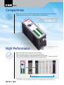
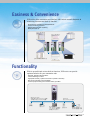
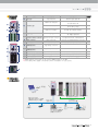
Leader in Electrics & Automation
Series
Programmable Logic Controller
Automation Equipment
Programmable Logic Controller
All-In-One PLC
with Next Generation Technology
XGB series is the micro PLC that offers maximum
automation at minimum cost. With its high
performance and functionality, it can support from
simple control to complex task. Strengthening its
communication functions, XGB offers user-oriented
integrated control. Based on its strengths, it can be
used in many fields of applications.
2
C o n t e n t s
4
Features
6
Main Unit
8
Input & Output
14
Special Functions
- High-speed Counter
- Positioning
- PID Cotrol
- Pulse Catch /
Input Filter/Task
- Analog Input /Output
26
Communication
- Fast ethernet
- Cnet
28
Software
30
Product list / Dimension
3
Compactness
XGB series is even more compact but provides powerful functions and performance.
Compact & Powerful solution is XGB’s steadfast competitiveness.
Item
W
H
D
Main Unit
30
20
90
90
60
60
Expansion Modules
This image was drawn to actual
size of the product.
High Performance
With its high-speed processing and system capability,
XGB series offers utmost efficiency for your applications.
�60ns/Step processing speed and floating-point arithmetic with on-board CPU
�Max. 7 expansion modules, Max. 480 I/O point control: PLC systems for Low - to-Mid level applications
�Max. 5-Port Communication with built-in functions and expansion modules
Main Unit
Network(2)*1)
Special function(7)*1)
Expansion I/O (7)*1)
Max. 7 expansion modules
*1) Each number in ( ) is the number of modules that can be mounted for each function (network,
special function, expansion I/O). And the total number of mountable expansion modules is limited to 7.
4
Easiness & Convenience
XGB series offers convenient user interface with various network diagnosis &
monitoring functions and back-up function.
�Enhanced user interface with XG5000/XG-PD
�Various monitoring functions.
�Network diagnosis and monitoring
�Batteryless back-up
Device monitoring
User event
Frame monitoring
Trend monitoring
Special module monitoring
Network Scan
Functionality
With its powerful and various built-in functions, XGB series can provide
optimum solution for your automation task.
�RS-232C, RS-485 communications
�2-axis Positioning functions
�High-speed counter (1-phase 4 channels / 2-phase 2 channels)
�PID control (Cascade control available)
�Various input processing such as Pulse catch, Input filter
High-speed counter
Single phase:Max.4channels,20kpps
Two phase:Max.2channels,10kpps
Encoder
Pulse catch
Input filter
Positioning
Max.2channels,100kpps
RS-232C/485
XGK dedicated protocol
User-defined protocol
Modbus-RTU/ASCII
LS Inverter
Servo/Stepping drive
Servo/Stepping motor
5
Main Unit >>
1
2
3
4
Descriptions
Item
Ambient temperature
Storage temperature
Ambient humidity
Storage humidity
0~55 �C
-25~+70 �C
5~95%RH (Non-condensing)
5~95%RH (Non-condensing)
Ocnasional vibration
Acceleration
Frequency
Pulse width
10 ≤ f < 57Hz
0.075mm
10 times
9.8m/s2(1G)
57 ≤ f ≤ 150Hz
each
IEC61131-2
5 Vibration resistance
direction
Continuous vibration
(X,
Y
and
Z)
Acceleration
Frequency
Pulse width
10 ≤ f < 57Hz
0.035mm
4.9m/s2(0.5g)
57 ≤ f ≤ 150Hz
2
�Peak Acceleration: 147m/s (15g) �Duration: 11ms
IEC61131-2
6 Shock resistance
�Pulse waveform: Half-sine, 3times each directon per each axis
Square wave
LSIS Standard
±1,500 V
impulse noise
IEC61131-2
Electrostatic
4kV
IEC61000-4-2
discharge
Radiated
7 Noise resistance
IEC61131-2
electromagnetic
27 ~ 500 MHz, 10V/m
IEC61000-4-3
field noise
Expansion module
Main unit
Fast transient/
IEC61131-2
IEC61000-4-4
Burst noise
1kV
2kV
Free
from
corrosive
gases
and
excessive
dust
8 Operating Ambience
Up to 2,000m
9 Altitude
Less than equal to 2
10 Pollution level *1)
Air-cooling
11 Cooling
*1) Pollution level indicates the degree to which conductive material is generated in the environment where the
equipment is used. Pollution level 2 is the condition that only non-conductive pollution occurred but
temporary conductivity may be produced due to condensing.
Item
Model
XBM-DN16S
XBM-DN32S
Repetitive, cyclic, interrupt, constant scan
Refresh mode (Batch processing by scan synchronization)
I/O control mode
Direct mode by instruction
Programming language
Ladder Diagram, Instruction List
No. of instructions
Basic : 28, Applied : 677
Processing speed
0.16㎲ /Step (for basic instruction)
Program capacity
10ksteps
Max. I/O points
480 points(Main + 7 expansions)
P0000 ~ P127F (2,048 points)
P
M0000 ~ M255F (4,096 points)
M
K00000 ~ K2559F (Special area : K2600~2559F) (40,960 points)
K
L00000 ~ L1279F (20,480 points)
L
F000 ~ F255F (4,096 points)
F
100ms, 10ms, 1ms : T000 ~ T255 (Changeable by Parameter setting)
T
Data memory
C000 ~ C255
C
S00.00 ~ S127.99
S
D0000 ~ D5119 (5,120 word)
D
U00.00 ~ U07.31 (Analog data refresh area : 256 word)
U
Z000~Z127 (128 word)
Z
N0000~N3935 (3,936 word)
N
128
Number of program
RUN, STOP, DEBUG
Operation mode
Self diagnosis
Operationdelay monitoring,memoryerror,I/Oerror,battery error, powererror,etc.
Program port
RS-232C (Loader) Remote connection using RS-232C, RS-485
Data retension at power failure
Latch range setting at Basic parameter
RS-232C/485, High-speed counter, PID control, Pulse catch, Input filter
Built-in function
External interrupt, Positioning*1)
Internal current consumption
400mA
280mA
300mA
Weight
100g
*1) XBM-DR16S doesn’
t have built-in positioning function.
Control method
6
XBM-DR16S
Descriptions
Descriptions
Input indication
Red On: Input signal On
Red Off: Input signal Off
PWR: Power indication
Red On: Power On
Red Off: Power Off
RUN: RUN indication
Green On: PLC Run
Green Off: PLC Stop
ERR: Error indication
Red On-and-Off: PLC Error
Red Off: PLC Normal condition
Output LED
On: Output signal On
Off: Output signal Off
Name
�
�
�
�
�
Input LED
Condition LED
�
�
�
�
�
�
�
Output LED
�
Expansion module connector Expansion module connector
Connection of expansion module
(I/O, Spacial function, Communication)
PADT connection
Connector for XG5000/XG-PD connection
Mode setting
Setting Run/Stop mode of PLC
�
Input connector
/Terminal block
Input wiring connection
-
Ouput wiring connection
-
Built-in RS-485 connection
RS-485 +/- terminal connection
�
PADT connector
�
Mode switch
�
�
�
�
Output connector
/Terminal block
�
�
�
Built-in RS-485 connector
�
Built-in RS-232C connector Built-in RS-232C connection RS-232C TxD, RxD, GND terminal connection
�
Power connector
�
�
Power supply connection
DC 24V power supply
*1)
*2)
*3)
*1) In the remote mode, set the mode switch to STOP.
*2) GND terminal of RS-232C can be used as GND terminal of RS-485.
*3) Select DC power supply considering current consumption of PLC system.
�
�
�
Main unit
RS-232C
XG5000
Communication
Special function
Expansion I/O
Max.7expansion modules
High-speed counter
Single phase:Max.4Ch,20kpps
Two phase:Max.2Ch,10kpps
Encoder
Positioning
Max.2Ch,100kpps
Pulse catch
/Input filter
XGT Panel
RS-232C/485
XGK dedicated protocol
User-defined protocol
Modbus-RTU/ASCII
LS Inverter
Servo/stepping drive
Servo/stepping motor
7
Input & Output >>
Model
Specifications
Input points
Insulation method
Rated input voltage/current
Operation voltage range
On voltage/On current
Off voltage/Off current
Input resistance
DC Input
Expansion module
XBM-DN32S XBE-DC08A
XBE-DC16A
XBE-DC32A
8points
16points
16points
32points
Photocoupler insulation
DC24V / 4mA (Contact 00~03: 7mA)
DC24V / 4mA
DC20.4~28.8V (Ripple rate < 5%)
DC19V or more / 3mA or more
DC6V or less / 1mA or less
5.6 kΪ (Contact 00~03: 3.3 kΪ )
5.6 kΪ
XBM-DR16S
8points
Off→On
Response time
External connection method
AC560Vrms / 3 Cycle (altitude 2000m)
10㏁ or more by megger
8 points/COM
16 points/COM 8 points/COM 16 points/COM
32 points/COM
Twisted wire 0.3~0.75mm2 (external diameter ≤ 2.8mm)
Input On LED On
30mA
240mA
300mA
40mA
50mA
100mA
400mA
9-pin terminal
block
20-pin
connector
20-pin
connector
10-pin terminal 8-pin + 10-pin
terminal block
block
40-pin
connector
40-pin
connectorX2
Output point
Insulation method
Rated load voltage
Load voltage range
Transistor output
XBM-DN16S XBM-DN32S XBE-TN08A XBE-TP08A XBE-TN16A XBE-TP16A XBE-TN32A XBE-TP32A XBE-TN64A XBE-TP64A
16points
32points
64points
8points 16points
8points
Photocoupler
DC 12/24V
DC 10.2 ~ 26.4V
Max. load current
0.2A/point
Model
Specifications
0.2A/point,
2A/COM
Response time
Off→On
On→Off
COMMON method
Internal current consumption
Voltage
External
power supply
Current
0.5A/1 point
8points
/COM
16points
/COM
180mA
200mA
24mA or less
(DC 24V connection)
8points/COM
Model
Output point
Insulation method
Rated load voltage/current
Min. load voltage/current
Max. load voltage/current
Off leakage current
Max. on/off frequency
Surge absorber
Mechanical
Response time
32points/COM
10mA or less (DC 24V connection)
200mA
40mA or less
20mA or less
(DC 24V connection) (DC 24V connection)
Output On, LED On
External connection method
Service life
16points/COM
40mA
60mA
120mA
DC12/24V ± 10% (Ripple voltage ≤ 4 Vp-p)
Operation indicator
Specifications
0.1A/point, 2A/COM
0.2A/point, 2A/COM
0.1mA or less
DC 0.4V
Zenor diode
1mA or less
1ms or less (Rated load, resistive load)
Off leakage current
Max. voltage drop(On)
Surge absorber
Electrical
Off→On
On→Off
COMMON method
Internal current consumption
Operation indicator
External connection method
8
XBE-DC64A
64points
1 / 3/ 5/ 10 / 20 / 70 / 100ms(setting by CPU parameter) Initial value : 3ms
On→Off
Insulation pressure
Insulation resistance
COMMON method
Proper cable size
Operation indication
Internal current consumption
Main unit
XBM-DN16S
8points
20-pin connector
10-pin
terminal block
8-pin + 10-pin
terminal block
40-pin connector
40-pin
connector x 2
Relay output
XBE-RY08A
XBE-RY16A
8points
16points
Relay insulation
DC24V 2A(resistive load)/AC220V 2A(COSΨ = 1), 5A/COM
DC5V/1mA
AC250V, DC125V
0.1mA (AC220V, 60Hz)
3,600 times/hr
None
20 million times or more
Rated load voltage/current 100,000 times or more
AC200V/1.5A, AC240V/1A (COSΨ = 0.7) 100,000 times or more
AC200V/1A, AC240V/0.5A (COSΨ = 0.35) 100,000 times or more
DC24V/1A, DC100V/0.1A (L / R = 7ms) 100,000 times or more
10 ms or less
12 ms or less
8 points/1COM
230mA
360mA
420mA
Output On, LED On
9-pin terminal block connector
9-pin terminal block connectorx2
XBM-DR16S
8points
8-point DC input
8-point NPN output
8-point PNP output
XBM-DR16S
XBE-TN08A
XBE-TP08A
8-point Relay output
16-point Relay output
XBM-DR16S, XBE-RY08A*Note1)
XBE-RY16A
*Note1) The address of XBE-RY08A is assigned as contact point 00~07.
XGB module
Main unit
(20+20 pin)
Expansion
input(40 pin)
Expansion
output(40 pin)
Smart Link
Descriptions
Cable number
Cable specifications
40 Pin
Main Unit I/O wiring
SLP-CT101-XBM
Soft tube type 1m
40 Pin
32/64-point expansion I/O wiring
SLP-CT101-XBE
Soft tube type 1m
SLP-CT101-XBE
Soft tube type 1m
SLP-T40P
SLP-RY4A
40 Pin 32/64-point expansion output wiring
9
Input & Output >>
PLC
Pin number
Smart Link
XBM-DN32S
B10
00
00
B09
01
01
B1
B08
02
02
A2
A1
B07
03
03
B2
B06
04
04
A3
B05
05
05
B3
B04
06
06
A4
B03
07
07
B4
B02
COM 0
COM 0
A5
B01
COM 0
COM 0
B5
A10
NC
08
A6
A09
NC
09
B6
A08
NC
0A
A7
A07
NC
0B
B7
A06
NC
0C
A8
A05
NC
0D
B8
A04
NC
0E
A9
A03
NC
0F
B9
A02
NC
COM 1
A10
A01
NC
COM 1
B10
PLC
Pin number
10
SLP-T40P
XBM-DN16S
Smart Link
SLP-T40P
XBM-DN16S
XBM-DN32S
B10
20
20
A11
B09
21
21
B11
B08
22
22
A12
B07
23
23
B12
B06
24
24
A13
B05
25
25
B13
B04
26
26
A14
B03
27
27
B14
B02
+12/24V
+12/24V
A15
B01
+12/24V
+12/24V
B15
A10
NC
28
A16
A09
NC
29
B16
A08
NC
2A
A17
A07
NC
2B
B17
A06
NC
2C
A18
A05
NC
2D
B18
A04
NC
2E
A19
A03
NC
2F
B19
A02
COM 0
COM 0
A20
A01
COM 0
COM 0
B20
PLC
Pin number
B20 A20
Smart Link
XBE-DC32A*Note1)
XBE-DC64A
XBE-TN32A*Note1)
XBE-TN64A
XBE-TP32A*Note1)
XBE-TP64A
00(20)
00(20)
10(30)
00(20)
10(30)
10(30)
SLP-T40P
SLP-RY4A*Note2)
(I/O link terminal) (Relayoutputboard)
A1
A11
P00
P10
B19
A19
01(21)
11(31)
01(21)
11(31)
01(21)
11(31)
B1
B11
P01
P11
B18
A18
02(22)
12(32)
02(22)
12(32)
02(22)
12(32)
A2
A12
P02
P12
B17
A17
03(23)
13(33)
03(23)
13(33)
03(23)
13(33)
B2
B12
P03
P13
B16
A16
04(24)
14(34)
04(24)
14(34)
04(24)
14(34)
A3
A13
P04
P14
B15
A15
05(25)
15(35)
05(25)
15(35)
05(25)
15(35)
B3
B13
P05
P15
B14
A14
06(26)
16(36)
06(26)
16(36)
06(26)
16(36)
A4
A14
P06
P16
B13
A13
07(27)
17(37)
07(27)
17(37)
07(27)
17(37)
B4
B14
P07
P17
B12
A12
08(28)
18(38)
08(28)
18(38)
08(28)
18(38)
A5
A15
P08
P18
B11
A11
09(29)
19(39)
09(29)
19(39)
09(29)
19(39)
B5
B15
P09
P19
B10
A10
0A(2A)
1A(3A)
0A(2A)
1A(3A)
0A(2A)
1A(3A)
A6
A16
P0A
P1A
B09 A09
0B(2B)
1B(3B)
0B(2B)
1B(3B)
0B(2B)
1B(3B)
B6
B16
P0B
P1B
B09 A08
0C(2C)
1C(3C)
0C(2C)
1C(3C)
0C(2C)
1C(3C)
A7
A17
P0C
P1C
B07
A07
0D(2D)
1D(3D)
0D(2D)
1D(3D)
0D(2D)
1D(3D)
B7
B17
P0D
P1D
B06 A06
0E(2E)
1E(3E)
0E(2E)
1E(3E)
0E(2E)
1E(3E)
A8
A18
P0E
P1E
B05 A05
0F(2F)
1F(3F)
0F(2F)
1F(3F)
0F(2F)
1F(3F)
B8
B18
P0F
P1F
B04 A04
NC
NC
NC
NC
NC
NC
A9
A19
NC
NC
B03 A03
NC
NC
NC
NC
NC
NC
B02 A02
B01
A01
COM
COM
DC12/24V
COM
COM
0V
B9
B19
NC
NC
A10
A20
+24V
24G
B10
B20
+24V
24G
*Note1) The number inside ( ) is the address of 64-point I/O module.
*Note2) SLP-RY4A can be connected to only NPN transistor output module.
11
Input & Output >>
12
DC input circuit
Relay output circuit
NPN Type TR output
PNP Type TR output
According to external equipment type, refer to the following connection between DC input part
and external devices.
External equipment (I/Os)
Input part
External equipment (I/Os)
Relay
output
type
PNP
Current
output
type
NPN
Open
collector
output
type
Voltage
output
type
Input part
NPN
Current
output
type
13
Special functions >>
High-speed counter
With XGB’
s various special functions,
you can configure
ALL-IN-ONE system.
Main unit
RS-232C
XG5000
Communication
High-speed counter
Single phase: Max. 4Ch, 20kpps
Two phase: Max. 2Ch, 10kpps
Encoder
Special function
Expansion I/O
Max. 7 expansion modules
Positioning
Max. 2Ch, 100kpps Servo/stepping drive
Pulse catch/Input filter/Task
Servo/stepping drive
Servo/stepping motor
14
High speed counter accurately counts the number of high speed pulse generated from encoder or
pulse generator.
High-speed counter terminal
Encoder
High-speed counter
One phase : Max. 4Ch, 20kpps
Two phase : Max. 2Ch, 10kpps
1-Phase
Terminal
number
Signal name
Description
Signal name
Description
000
Ch0 counter input
Counter input
Ch0 A-axis input
A-axis input
001
Ch1 counter input
Counter input
Ch0 B-axis input
B-axis input
002
Ch2 counter input
Counter input
Ch2 A-axis input
A-axis input
003
Ch3 counter input
Counter input
Ch2 B-axis input
B-axis input
004
Ch0 preset24V
Preset input
Ch0 preset24V
Preset input
005
Ch1 preset24V
Preset input
-
-
006
Ch2 preset24V
Preset input
Ch2 preset24V
Preset input
007
Ch3 preset24V
Preset input
-
-
COM0
Input COMMON
COMMON
Input COMMON
COMMON
Function specifications
Pulse input
mode
Counter
mode
Performance specifications
Performance
Specifications
Functions
�Incremental/Decremental counter by program
when input is 1-phase pulse
�Incremental/Decremental counter by B-axis input
when input is 1-phase pulse
�Incremental/Decremental counter by Incremental/
Decremental input when input is 2-phase pulse
�Incremental/Decremental counter (4 multiplication)
by phase difference when input is 2-phase pulse
�Incremental counter by CW/CCW input
�Linear counter
�Ring counter : Counter rotating between value in
0 ~ (Ring counter setting value-1)
�Changes present value of counter to optional value
Present
value preset - Internal preset / External preset
Comparison
output
No. of
rotation
2-Phase
�Sets output contact when counter value corresponds
with comparison output condition
- Comparison output condition : >, >=, =, <=, <,
inclusion, exclusion
�Outputs the rotation number of input pulse per
unit time
Specifications
No. of points 1-phase 4points, 2-phase 2points
Input points
Counting
range
A phase, B phase, Preset input
Linear counter: -2,147,483,648 ~
2,147,483,647 (Binary 32Bit)
Ring counter: 0 ~ 2,147,483,647
Counting speed 1-phase 20kpps/2-phase 10kpps
Incrementalal Ring counter, preset , Rotation
number per unit time ,
functions
Comparison output, Latch counter
Electrical specifications
Item
Specifications
Input voltage
DC 24V
(20.4V ~ 28.8V)
Input current
7mA
On guaranteed voltage (Minimum)
DC 20.4V
Off guaranteed voltage (Maximum) DC 6V
Encoder wiring
Voltage output encoder
Open collector encoder
15
Special functions >>
High-speed counter
Operation setting address of high-speed counter
Item
Device range for each channel
Ch3
Ch2
K2700
K2800
Counter enable
Counter internal preset assignment
K2601
K2701
K2801
K2901
Bit
Counter external preset enable
K2602
K2702
K2802
K2902
Bit
Substraction counter assignment
K2603
K2703
K2803
K2903
Bit
Comparison output enable
K2604
K2704
K2804
K2904
Bit
Rotation number per unit time enable
K2605
K2705
K2805
K2905
Bit
Latch counter enable
K2606
K2706
K2806
K2906
Bit
Carry signal(Bit)
K2610
K2611
K2612
K2710
K2711
K2712
K2810
K2811
K2812
K2910
K2911
K2912
Bit
Bit
Bit
Borrow signal
Comparison output signal
Ch4
K2900
Remark
Ch1
K2600
Bit
Parameter setting address of high-speed counter
Item
Counter type selection
Setting value
Descriptions
Setting descriptions
h0000 Linear counter setting
h0001
Ring counter setting
Device range for each channel
Ch0
Ch1
Ch2
Ch3
Remark
K300
K330
K360
K390
Word
K301
K331
K361
K391
Word
K302
K332
K362
K392
Word
h0000 1 phase 1 input 1 multiplication
Pulse input mode setting
h0001
1 phase 2input 1 multiplication
h0002 CW/CCW
h0003 2phase 4multiplication
h0000 (Single comparison) <
h0001
(Single comparison) ≤
h0002 (Single comparison) =
Comparison output mode setting
h0003 (Single comparison) ≥
h0004 (Single comparison) >
h0005 (Section comparison) Inclusion
h0006 (Section comparison) Exclusion
Internal preset value setting
K304
K334
K364
K394
Double word
-2,147,483,648 ~ 2,147,483,647
K306
K336
K366
K396
Double word
Max. Ring counter value setting
-2,147,483,648 ~ 2,147,483,647
K310
K340
K370
K400
Double word
Min. Comparison output value setting
-2,147,483,648 ~ 2,147,483,647
K312
K342
K372
K402
Double word
Max. Comparison output value setting -2,147,483,648 ~ 2,147,483,647
K314
K344
K374
K404
Double word
K320
K350
K380
K410
Word
Comparison output contact assignment
16
-2,147,483,648 ~ 2,147,483,647
External preset value setting
0x0000
P20
0x0001
P21
0x0002
P22
0x0003
P23
0x0004
P24
0x0005
P25
0x0006
P26
0x0007
P27
Rotation number setting per unit time
0 ~ 60000
K322
K352
K382
K412
Double word
Pulse number setting per rotation
0 ~ 60000
K323
K353
K383
K413
Double word
�Special function Monitoring
Special function Monitoring in XG5000 can monitor operation condition and data of
high speed counter while PLC is On-line.
�Device Monitoring
While PLC is On-line, Device Monitoring can monitor the operation condition and data
by monitoring the Device setting area.
Parameter setting address of high-speed counter
Device range for each channel
Item
Ch1
Ch2
Ch3
Ch4
Remark
Present counter value
K262
K272
K282
K292
Double word
No. of rotations per unit time
K264
K274
K284
K294
Double word
Error code
K266
K276
K286
K296
word
Error code of high-speed counter
Error code
(decimal)
Error description
20
Out of counter type range
21
Out of pulse input type range
22
When requesting RUN of CH1[3] during 2-phase operation of CH0[2]
( Use of CH1[3] is not available during 2-phase operation of CH0[2] )
23
Out of Comparison output type range
25
Internal preset value setting error ( Out of counter range)
26
External preset value setting error ( Out of counter range)
27
Ring counter setting error (Ring counter value should be set as 2 or more)
28
Comparison minimum value setting error ( Out of maximum input range)
29
Comparison maximum value setting error ( Out of maximum input range)
30
Minimum comparison output 1 > Maximum comparison output 1
31
Contact assignment value setting error of comparison output
34
Out of unit time setting range
35
Out of pulse value range per rotation
17
Special functions >>
Positioning
Positioning function is to control servo/stepping motor connected to servo/stepping drive by
supplying high-speed pulse to the drive.
Positioning function terminal
Pin layout Item
Out
put
Servo/Stepping drive
Servo/Stepping motor
Pin number
X axis Y axis
A1
A2
A3
A4
A9/A10
B9/B10
Input
Positioning
Max. 2 channels, 100kpps
Signal name
Direction of positioning Operating
signal to external condition
Pulse output (Open collector)
→
-
Direction Pulse output (Open collector)
→
-
DC 24V
External 24V power supply
→
-
Output COM External 24V GND
→
-
Pulse
A1
A3
Limit L
Low limit
←
Edge
A2
A4
Limit H
High limit
←
Edge
A5
A7
DOG
Near point
←
Edge
A6
A8
Zero
Zero signal (+24V)
←
Edge
Common
←
-
A9/A10, B9/B10 Input COM
Performance specifications
Remark
Description
2 axes
2-axis linear interpolation
Position control, Speed control, Speed/Position switching control,
Position/speed switching control
Pulse
30-step pattern for each axis (set in XG5000)
(operation step number : 1 � 30)
Dedicated monitoring function for positioning in XG5000
Permanent Backup of downloaded parameter (FLASH memory)
2-month Super Cap. Backup of parameter/data modified during operation (RAM)
Permanent Backup of parameter/data in RAM by instruction (FLASH memory)
Absolute / incremental method
-2,147,483,648 � 2,147,483,647
1 � 100,000(pulse/sec)
-
Item
No. of control axis
Interpolation
Control mode
Control unit
Positioning data
Positioning monitor
Back-up
Positioning method
Positioning range
Speed range
Positioning Acceleration /
Deceleration type
Trapezoidal acceleration / deceleration
Acceleration /
Deceleration time
1 � 10,000㎳
-
(4 patterns each can be set)
100 Kpps
2m
Max. output pulse
Max. distance of connection
-
Electric specifications
Signal
Output
Output pulse
Signal
External high limit
Input
External low limit
Approximate zero
Zero
18
Rated input
voltage
Leakage
Response
Max. load current/
Max. voltage
current (Off)
time
inrush current
drop (On)
100μs
100mA (1 point)1A/
DC 5�24V DC 4.75�26.4V
DC 0.3V or less 0.1mAorless
10ms or less
or less
Response
Off voltage/
Rated input
Load voltage
Input
On voltage/
time
current
voltage/current
range
resistance
current
DC 24V/7mA
DC 24V/4mA
Load voltage
range
DC 20.4
�28.8V
DC 19V/5.7mA
or more
DC 6V/1.8mA
or less
3.3 ㏀
DC 19V/3.4mA
or more
DC 6V/1.1mA
or less
5.6 ㏀
0.5ms
or less
Parameter setting and test operation
After setting and downloading positioning parameters, test operation is available through
command setting window in positioning monitoring.
�
Positioning parameter setting
Test operation by command setting window
Storage range of positioning parameter
Assigned parameters are stored in the following memory range. While operating PLC,
these parameters can be changed by changing data in corresponding range.
Item
Setting range
Positioning
0 : disabled, 1 : enabled
Pulse output level
0 : Low active, 1 : High active
Bias Speed
1 � 100,000 [pulse/sec]
Speed limit
1 � 100,000 [pulse/sec]
Acceleration time 1
0 � 10,000 [Unit:ms]
Deceleration time 1
0 � 10,000 [Unit:ms]
Acceleration time 2
0 � 10,000 [Unit:ms]
Deceleration time 2
0 � 10,000 [Unit:ms]
Basic
Acceleration time 3
0 � 10,000 [Unit:ms]
parameter
Deceleration time 3
0 � 10,000 [Unit:ms]
Acceleration time 4
0 � 10,000 [Unit:ms]
Deceleration time 4
0 � 10,000 [Unit:ms]
Soft high limit
-2,147,483,648�2,147,483,647[pulse]
Soft low limit
-2,147,483,648�2,147,483,647[pulse]
Backlash compensation amount
0 � 65,535 [pulse]
Detection of soft high/low limit
0 : disabled, 1 : enabled
during equal speed operation
Use of high / low limit
0 : disabled, 1 : enabled
Zero address
-2,147,483,648�2,147,483,647[pulse]
Zero-return high speed
1 � 100,000 pulse/sec
Zero-return low speed
1 � 100,000 pulse/sec
Zero-return Acceleration time
0 ~ 10,000 [Unit:ms]
Zero-return Deceleration time
0 ~ 10,000 [Unit:ms]
Zero-return dwell time
0 ~ 50,000 [Unit:ms]
Zero/
manual Zero-return method
parameter
Zero-return direction
JOG high Speed
JOG low Speed
JOG Acceleration time
JOG Deceleration time
Inching speed
0 : Zero detection after near zero OFF
1 : Zero detection after deceleration
when near zere is ON
2 : Zero detection by near zero
0 : Forward, 1 : Reverse
1 � 10,000 pulse/sec
1 � 10,000 pulse/sec
0 ~ 65535 [Unit:ms]
0 ~ 65535 [Unit:ms]
1 � 65,535 [pulse/sec]
Initial value
Device range
X axis Y axis
0
K4870
0
K4871
1
K450
100,000
K452
500
K454
500
K455
1,000
K456
1,000
K457
1,500
K458
1,500
K459
2,000
K460
2,000
K461
2147483647
K462
-2147483648 K464
0
K466
Remark
K5270
K5271
K490
K492
K494
K495
K496
K497
K498
K499
K500
K501
K502
K504
K506
Bit
Bit
Double word
Double word
Word
Word
Word
Word
Word
Word
Word
Word
Double word
Double word
Word
0
K4684
K5084
Bit
1
0
5,000
500
1,000
1,000
0
K4872
K469
K471
K473
K475
K476
K477
K5272
K509
K511
K513
K515
K516
K517
Bit
Double word
Double word
Double word
Word
Word
Word
0
K4780
K4781
K5180
K5181
Word
1
5,000
1,000
1,000
1,000
100
K4782
K479
K481
K483
K484
K485
K5182
K519
K521
K523
K524
K525
Bit
Double word
Double word
Word
Word
Word
19
Special functions >>
Positioning
Operation command using programming
Writes a positioning program using positioning flag and its dedicated instructions.
Zero Return
Error Reset
DST
Positioning dedicated instruction
Instruction *1)
Descriptions
Instruction Operand *1)
ORG
FLT
Zero return start
Floating-point zero setting
DST
Direct start
IST
LIN
SST
Indirect start
Linear interpolation start
Simultaneous start
VTP
PTV
STP
Speed/Position conversion
Position/Speed conversion
Stop
Slot, Instruction axis
Slot, Instruction axis
Slot, Instruction axis, Position, Speed, Dwell time,
M code, Control word
Slot, Instruction axis, Step number
Slot, Instruction axis,step number, Axis information
Slot, Instruction axis, X-axis step number,
Y-axis step number, Z-axis step number, Axis information
Slot, Instruction axis
Slot, Instruction axis
Slot, Instruction axis, Deceleration
SSP
Position synchronization
Slot, Instruction axis, Step number,
Master-axis position, Master-axis setting
SSS
Speed synchronization
Slot, Instruction axis, Master-axis ratio, Slave-axis ratio,
Master-axis setting
POR
Position override
Slot,
SOR
Speed override
Slot,
PSO
Positioning speed override
Slot,
INCH
Inching
Slot,
MOF
M code off
Slot,
PRS
Present position preset
Slot,
EMG
Emergency stop
Slot,
CLR
Error reset, Output disable annulment
Slot,
WRT
Parameter/Operation data saving
Slot,
*1) In instruction, the slot should be assigned as number '0'.
Instruction
Instruction
Instruction
Instruction
Instruction
Instruction
Instruction
Instruction
Instruction
axis,position
axis,speed
axis,position,speed
axis, Inching amount
axis
axis,position
axis
axis, Pulse output enable / disable
axis,-axis information
Operation data range for Positioning
Step
number
1
Item
Coordinates
Operation pattern
Control method
Operation method
Repeating step
Targeted position
M Code number
Accel/Decel number
Operation speed
Dwell time
2
3
4~29
30
20
Device range
Intial
Remark
value
X-axis
Y-axis
Absolute K5384
K8384
Bit
0 : Absolute, 1 : Relative
K5382~3 K8382~3
End
Bit
0 : End, 1 : Continue, 2 : Repeat
Position K5381
K8381
Bit
0 : Positon control, 1 : Speed control
K5380
K8380
Bit
0 : Single operation, 1 : Repeated operation Single
word
K539
K839
0
0 ~ 30
Double word
0
K530
K830
-2,147,483,648 ~ 2,147,483,647 [pulse]
word
0
K537
K837
0 ~ 65,535
Bit
K5386
K8386
0 : Number 1, 1: Number 2,
0
2: Number 3, 3: Number
Bit
K5387
K8387
1 ~ 100,000 [pulse/sec]
Double word
K534
0
K834
word
0
1 ~ 50,000 [pulse/sec]
K536
K836
K540~549 K840~849
Same items as Step number 0
K550~559 K850~859
Same items as Step number 0
K560~810 K860~1119
Same items as Step number 0
K820~829 K1120~1129
Same items as Step number 0
Specification
Operation monitoring range for Positioning
Device range
X axis
Item
Word
Busy signal
ERROR
Positioning completed
M code On
Zero determination
Output disable
Stop
High limit detection
Low limt detection
Emergency stop
Forward/Reverse rotation
Operation (acceleration)
Operation (fixed speed)
Operation (deceleration)
Operation (dwell)
Operation control (position control)
Operation control (speed control)
Operation control (linear interpolation)
Zero return
Position synchronization
Speed synchronization
JOG low speed
JOG high speed
Inching
Present position
Present speed
Step number
Error code
M code
JOG operation (start)
JOG forward operation
JOG reverse operation
JOG low/high speed
K420
K421
K422
K424
K426
K427
K428
K429
Remark
Y axis
Bit
Address
0
1
2
3
4
5
6
8
9
A
B
C
D
E
F
0
1
2
5
6
7
8
9
A
0
1
2
3
K4200
K4201
K4202
K4203
K4204
K4205
K4206
K4208
K4209
K420A
K420B
K420C
K420D
K420E
K420F
K4210
K4211
K4212
K4215
K4216
K4217
K4218
K4219
K421A
K422
K424
K426
K427
K428
K4290
K4291
K4292
K4293
Word
K430
K431
K432
K434
K436
K437
K438
K439
Bit
Address
0
1
2
3
4
5
6
8
9
A
B
C
D
E
F
0
1
2
5
6
7
8
9
A
0
1
2
3
K4300
K4301
K4302
K4303
K4304
K4305
K4306
K4308
K4309
K430A
K430B
K430C
K430D
K430E
K430F
K4310
K4311
K4312
K4315
K4316
K4317
K4318
K4319
K431A
K432
K434
K436
K437
K438
K4390
K4391
K4392
K4393
Operation
monitoring
JOG
command
Wiring with DC 5V
Wiring with DC 24V
Stepping motor / drive
21
Special functions >>
PID control Pulse catch Input filter Task
Features
�Built-in PID control function in XGB’
s main unit.
�Various control operation (P, PI, PD, PID, On/Off)
�PWM (Pulse Width Modulation) output of control result
�Forward, Reverse, Forward/Reverse Mixed Operation
�Enhanced responsivity to disturbance with cascade loop
�Available to use 2 set values and PID parameter simultaneously according operation zone
�Various PID control configurations with its SV Ramp, PV Tracking, Delta MV, MV Preset, alarm functions
Performance specifications
Item
No. of control loop
16-loop independent control
Control mode
P control, PI control, PD control, PID control
Control period
10ms ~ 6,563.5ms (Setting unit : 0.1ms)
Forward/Reverse
Mixed control
Function
Switching control direction automatically when exceeding dead band
Cascade
Improved control precision by serial connection between Master loop and Slave loop
SV Ramp
Preventing overload caused by excessive SV change by setting variation slope
Alarm
Auto tuning
Additional
function
22
Specification
Improved control stability with various alarm function such as MV high limit/low limit,
PV high limit/low limit, PV variation width
Auto tuning with improved auto-tuning algorithm
PWM output, PV Tracking, � MV, � PV, etc
When the On-condition time of input signal (P0000~P0007) is shorter than 1 scan time (Min. 50㎲ ),
Pulse catch processes the input signal as normal input.
External input signal
Input image data
Specifications
Item
8 points : P000 ~ P007
No. of setting points
50㎲
Min. pulse width
Input filter prevents processing of the input signal that is shorter than the filtering time. (Filtering time
is set by parameter) In the application site where noise is frequently generated, input filter prevents
wrong input caused by noise.
External input signal
Input image data
Item
Specifications
Every input contact
No. of setting points
Assigning for each module
Input filtering time setting
1 ~ 100㎳
Setting range
(1,3,5,10,20,70,100)
Task function is the processing method of internal/external signal generated preriodically or
aperiodically. (Total 24 task can be assigned.) It stops operation of scan program for the moment
and then execute the assigned task.
2. Fixed-cycle task setting
1. Initialization task setting
Item
Running a task one time before INIT_DONE
at initial execution
3. External points task setting
Item
No. of setting points
Min. pulse width
Condition
Description
8 points : P000 ~ P007
Min. 50㎲
No. of setting points
Setting range
Description
8 points
1~42,94,967,295ms
4. Internal device task setting
Item
No. of setting points
Condition
Description
8 points
Up, Down, Change, On, Off
Up, Down, Change
23
Special functions >>
Analog input output
Performance specifications
Specifications
Item
Analog range
Analog input
Analog output
XBF-AD04A
XBF-DV04A
DC 0 � 10 V (input resistance: 1 MΪ min.)
DC 4 � 20 mA
DC 0 ~ 20 mA (input resistance 250 Ϊ )
DC 0 ~ 10V(Load resistance ≥ 1㏀ )
�Analog input range can be selected by
Analog range
selection
user(sequence) program or I/O parameter
in XG5000.
�Each input range can be set for each channel.
0~10 V 4~20 mA 0~20 mA
Analog range
Signed Value
Precise Value
0 ~ 10 V
0 ~ 4000
Unsigned Value
Digital data
-
0 ~ 4000
-2000 ~ 2000
-2000 ~ 2000
400~2000
0 ~ 1000
0~1000
0~2000
0 ~ 1000
Percentile Value
0 ~ 1000
Data format of digital output is set by user program or software package.
(Setting for each channel is available.)
Analog input
Resolution
(1/4000)
0 ~ 10 V
2.5 mV
Resolution
Analog
input
4 ~ 20mA
Max. conversion speed
0 ~ 20mA
1.5ms / channel
Max. absolute input/output
±15 V
Accuracy
±0.5% or less
Resolution
(1/4000)
Resolution (1/4000)
5.0 ㎂
2.5mV
1ms / channel
±25mA
±15 V
±0.5% or less
4 channel / module
Analog I/O channels
Photocoupler insulation between I/O terminal and power supply
Insulation method
Connection terminal
11-point terminal block
Occupied I/O points
Fixed type : 64 points
Current consumption
(DC 24V)
DC 24V : 80㎃
(External input)
DC 24V : 200㎃
(External input)
Names and Functions
Name
�
Descriptions
Indicates condition of module
�LED On: Normal condition
�
RUN LED
�LED On and Off: Error
�LED Off: Power Off or module
malfunction
�
�
�
�
�
24
�
Input selection
switch
External connection
Voltage/Current selection termianl
�V : Voltage input selection
�I : Current input selection
External device connection
terminal
External power
supply terminal
External DC 24V input
Wiring with 2-wire sensor
Wiring 4-Wire sensor
※ Use 22AWG, 2 conductor, twist shielded cable when wiring between analog module and external device.
Output
value
selection
Digital
Precise value
Percentile -2,000
~
value
4~20mA 0~20mA 0~10V
2,000
0
~
4,000
2,023
2,000
2,023
2,000
1,011
1,000
1,011
1,000
2,047
2,000
4,047
4,000
1,600
1,500
750
750
1,000
3,000
1,200
1,000
500
500
0
2,000
800
500
250
250
-1,000
1,000
400
381
0
0
0
-2,000
-2,048
0
-48
*Note1)
*Note1)
output
0~10V
0~20mA
4~20mA
Analog
input
0
0
4
2.5
5
8
5
10
12
7.5
15
16
10
20
20
*Note1) supported in case analog input is 4~20mA
XBF-AD04A
Device
XBF-DV04A
U0x.00.0
Module ERROR flag
Device
U0x.00.0
U0x.00.F
Module READY flag
U0x.00.F
Module READY flag
Channel 0 operation flag
U0x.01.0
Channel 0 operation flag
U0x.01.1
Channel 1 operation flag
U0x.01.2
Channel 2 operation flag
U0x.01.3
Channel 3 operation flag
U0x.02.0
Channel 0 output permission setting
U0x.02.1
Channel 1 output permission setting
U0x.02.2
Channel 2 output permission setting
U0x.01.0
Description
R/W
Description
Module ERROR flag
U0x.01.1
Channel 1 operation flag
U0x.01.2
Channel 2 operation flag
U0x.01.3
Channel 3 operation flag
U0x.02
Channel 0 digital output
U0x.03
Channel 1 digital output
U0x.04
Channel 2 digital output
U0x.02.3
Channel 3 output permission setting
U0x.05
Channel 3 digital output
U0x.03
Channel 0 digital input value
U0x.11.0
ERROR clear request flag
U0x.04
Channel 1 digital input value
U0x.05
Channel 2 digital input value
U0x.06
Channel 3 digital input value
R
W
R/W
R
W
25 25
Communication >>
Fast ethernet Cnet
Features
�10/100Base-Tx Fast Ethernet for industrial use (IEEE802.3)
�Dedicated service for HMI connection (XGT dedicated/MODBUS-TCP protocol)
�High-speed link communication with high-level PLC (XGT/MASTER-K/GLOFA-GM)
�Remote program, Remote monitoring with XG5000 remote service
�Network security with Host Table (limitation of unwanted connections)
�Convenient network system setting and various self-diagnosis/monitoring with XG-PD
- Monitoring network information (Auto Scan)
- Checking module in network (PING)
- Providing information of each service
(high-speed link, P2P, dedicated service, media condition)
�User protocol editing and P2P service (communication with other brand’s equipment)
Network with ethernet
GLOFAView
GLOFAView
IFOS
MASTER-K
GLOFA-GM
XGT Panel
XGB
XGT
Other Ethernet
Performance specifications
Item
Communication spec.
TCP/IP, UDP/IP
Protocol
With LS PLCs
Service With other devices
High-speed link, P2P service
P2P service
Application
Dedicated protocal service, XG5000 service
HS link sending/receiving data
200words/block(Max.128blocks)
No. of channel connectable
to upper stage
Service
Media
Current consumption (mA)
26
XBL-EUMTA
10/100BASE-TX
8 channels
Communication with PC(HMI) and external devices,
High-speed communication among LSIS PLCs
UTP/STP Category 5
410
Features
�Max. 2 module mountable for 1 main unit. Total 5 channels of communication in 1 XGB system. (including loader)
�Max. 32-unit connection through Cnet
�Protocol editing and parameter setting using XG-PD
�Flexible communication speed setting (300~115,200bps)
�Long-distance communication system using dedicated modem (expansion RS-232C Communication module)
�Full duplex/ Half duplex communication (expansion RS-422 Communication module)
�PTP : User-defined Communication and XGT/MODBUS Communication Master
�XGT dedicated/MODBUS-RTU/ASCII drivers for HMI connection
�Various diagnosis functions using XG-PD (I/O information, CPU, Link, Service, LOG)
�Simultaneous monitoring of sending/receiving frame and checking the result of frame
�Communication service information (Checking information of dedicated service, P2P service)
System configuration
RS-232C
XG5000
Main Unit
Dedicated modem
Dedicated
modem
RS-232C/485
XGK dedicated protocol
User-defined protocol
Modbus-RTU/ASCII
Other net devics
XGT Panel
Smart I/O
LS Inverter
XGB
Performance Specifications
Item
interface
Modem connection
Specification
Built-in RS-232C
XBL-C21A
Built-in RS-485
XBL-C41A
RS-232C 1Ch
RS-232C 1Ch
RS-485 1Ch
RS-422/485 1Ch
Remote communication with external devices via modem connection, Available for only RS-232C port.
Dedicated mode
communication
mode
1:1 or 1:N communication using LSIS decficated protocol
XG5000 mode
P2P mode
Operation Server(Slave)
mode
Master
Program upload/download and remote control
Communication by protocal using XG-PD (Interface with other PLCs),
XGT, MODBUS RTU/ASCⅡ master communication
Remote connection simultaneoualy using XGT/Modbus Server, user-defined
XGT, MODBUS RTU/ASCⅡ master, user-defined
Start Bit
1
Data Bit
7 or 8
Data type Stop Bit
1 or 2
Parity
Even/Odd/None
Setting
Basic parameter setting with XG-PD
Synchronization
Transmission speed (bps)
Asynchronous
Selectable among 1,200/2,400/4,800/9,600/19,200/38,400/57,600/115,200 bps
Station number setting
Up tp 32 stations from 0 to 31 with XG-PD
Transmission distsnce
RS-232C: Max. 15m (Extendfible by using modem), RS-422/485: Max. 500m
Modem communication
Not available
Network configuration
Not available
1:1
Diagnosis function
Max. number of installation
Available
Not available
1:N
Available through LED and XG-PD dagnosis service
Built-in
2
Built-in
2
27
Software >>
�Program editing & Engineering software
�Windows-based easy operation
�Multi-PLC, Multi-programming support
�Various monitoring and diagnosis functions
�Windows 2000, XP (Limited use in Windows 98, ME)
Variable Monitor
Ladder Monitor
Forcel I/O
Trend Monitor
Special Module Monitor
�Convenient network setting
�Extended monitoring function for network system and communication modules
�Fast interface with CPU by effective network management
�Various built-in diagnosis functions
(CPU condition, Link condition, Service condition, Auto scan, LOG, Frame monitoring)
Parameter setting
Network Scan
Link Monitoring
Fast Ethernet
XGT Panel
Cnet
Other PLC
Smart I/O
Other net devics
LS Inverter
Frame Monitoring
28
Service Condition Monitoring
�Cell type input window
�Cell-unit editing
�Auto Filling
�Compatibility with Microsoft EXCEL
�Redo & Undo
�Screen split editing
�Drag & Drop
Supports Drag & Drop for Project,
Variable/Statement, Ladder editing, Variable monitoring
�User-defined shortcut key
Enhances user convenience with user-defined shortcut key
�Remote connection with RS-485 Communication and Ethernet
Remote connection with Max. 32 main units using built-in RS-485 Communication
RS-232C
XG 5000
XG 5000
Remote connection using RS-485 Communication
Remote connection using Ethernet
User-defined event
By registering user-defined
event, users can read the
record of specified event
and use it for PLC operation
and debugging.
Trend monitoring
Device monitoring
Variable monitoring
Item
The charging value
of specific device
can be monitored
and saved as a file.
System requirement
O/S
Windows 2000, XP (Limited use in Windows 98, ME)
CPU
IBM compatible PC with Min. 200MHz Pentium processor
Memory
HDD
Serial Port
Min. 128M RAM
100 MB (Free memory space)
Communication port for program transmission (RS-232C)
Printer
Compatible with Window 98 or later
Mouse
Compatible with Window 98 or later
29
Product list / Dimension >>
Item
Model
Specifications
Remark
XBM-DR16S
DC24V power supply, 8-point DC24V input, 8-point relay output
-
XBM-DN16S
DC24V power supply, 8-point DC24V input, 8-point TR output,
Built-in positioning function
-
XBM-DN32S
DC24V power supply, 16-point DC24V input, 16-point TR output,
Built-in positioning function
-
XBE-DC08A
8-point DC24V input
-
XBE-DC16A
16-point DC24V input
-
XBE-DC32A
32-point DC24V input
-
XBE-RY08A
8-point relay output
-
XBE-RY16A
16-point relay output
-
XBE-TN08A
8-point Transistor(NPN) output
-
XBE-TN16A
16-point Transistor(NPN) output
-
XBE-TN32A
32-point Transistor(NPN) output
-
XBE-DR16A
8-point DC24V input, 8-point relay output
-
Expansion
special module
XBF-AD04A
4-channel analog input (current/voltage)
-
XBF-DV04A
4-channel analog output (voltage)
-
Expansion
Communication
module
XBL-CU41A
Cnet (RS-422/485) I/F
-
XBL-EHTA
Ethernet I/F
-
SLP-T40P
40-point I/O link terminal board
-
SLP-RY4A
32-point relay output board
-
SLP-CT101-XBM
Connection cable between XGB main unit and Smart Link
(I/O link terminal board)
Plastic hood type
SLP-CT101-XBE
Connection cable between 32/64 expansion I/O and Smart Link
(I/O link terminal board, relay output board)
Plastic hood type
PMC-310S
Connection cable(PC to PLC), 9pin (PC)-6pin (PLC), Soft tube type cable
Main unit
Expansion
I/Omodule
Smart Link
Loader Cable
Soft tube type
※ 64-point I/O and TR(PNP) output modules are under development. (XBE-DC64A, TN64A, TP8A, TP16A, TP32A, TP64A)
(Unit : mm)
W
Model
30
XBM-DT16/32S, XBM-DR16S
XBE-DC32A, XBE-TR32A,
20
XBE-DC32A, XBE-TR32A,
XBF-AD04A, XBF-DV04A
27
30
XBE-RY16A, XBL-EMTA
31
Leader in Electrics & Automation
� For your safety, please read user's manual thoroughly before operating.
� Contact the nearest authorized service facility for examination, repair, or adjustment.
� Please contact qualified service technician when you need maintenance.
Do not disassemble or repair by yourself!
Safety Instructions
� Any maintenance and inspection shall be performed by the personnel having expertise concerned.
www.lsis.biz
� HEAD OFFICE
Yonsei Jaedan Severance Bldg., 84-11, Namdaemunro 5-ga,
Jung-gu, Seoul 100-753, Korea
Te l. (82-2)2034-4870
Fax. (82-2)2034-4713
� Global Network
�LS Industrial Systems Tokyo Office �
�Tokyo, Japan
Address: 16F, Higashi-Kan, Akasaka Twin Towers 17-22, 2-chome, Akasaka, Minato-ku Tokyo 107-8470, Japan
Tel: 81-3-3582-9128 Fax: 81-3-3582-0065 e-mail: [email protected]
�LS Industrial Systems Dubai Rep. Office �
�Dubai, U.A.E
Address: P.O.Box-114216, API World Tower, 303B, Sheikh Zayed road, Dubai, UAE.
Tel: 971-4-3328289 Fax: 971-4-3329444 e-mail: [email protected]
�LS-VINA Industrial Systems Co., Ltd �
�Hanoi, Vietnam
Address: LSIS VINA Congty che tao may dien Viet-Hung Dong Anh Hanoi, Vietnam
Tel: 84-4-882-0222 Fax: 84-4-882-0220 e-mail: [email protected]
�LS Industrial Systems Hanoi Office �
�Hanoi, Vietnam
Address: Room C21, 5Th Floor, Horison Hotel, 40 Cat Linh , Hanoi, Vietnam
Tel: 84-4-736-6270/1 Fax: 84-4-736-6269
�Dalian LS Industrial Systems Co., Ltd. �
�Dalian, China
Address: No. 15 Liaohexi 3 Road, Economic and Technical Development zone, Dalian, China
Tel: 86-411-8273-7777 Fax: 86-411-8730-7560 e-mail: [email protected]
�LS Industrial Systems (Wuxi) Co., Ltd. �
�Wuxi, China
Address: 102-A National High&New Tech Industrial Development Area, Wuxi, Jiangsu, China
Tel: 86-510-534-6666 Fax: 86-510-522-4078 e-mail: [email protected]
�LS Industrial Systems International Trading (Shanghai) Co., Ltd �
�Shanghai, China
Address: Room E-G, 12 th Floor Huamin Empire Plaza, No.726, West Yan’an Road Shanghai 200050, P.R. China
Tel: 86-21-6278-4291 Fax: 86-21-6278-4372 e-mail: [email protected]
�LS Industrial Systems Shanghai Office �
�Shanghai, China
Address: Room 1705~1707, 17th Floor Xinda Commercial Building, No.322, Xian Xia Road Shanghai 200336, China
Tel: 86-21-6208-7610 Fax: 86-21-6278-4292
�LS Industrial Systems Beijing Office �
�Beijing, China
Address: B-Tower 17. Beijing Global Trade Center B/D. No. 36, BeisanhUanDong-Lu, DongCheong-District,
Beijing 100013, P.R. China
Tel: 86-10-6462-3254 Fax: 86-10-6462-3236 e-mail: [email protected]
�LS Industrial Systems Guangzhou Office �
�Guangzhou, China
Address: Room 1403, 14F, New Poly Tower, 2 Zhongshan Liu Road, GuangZhou, China
Tel: 86-20-8326-6754 Fax: 86-20-8326-6287 e-mail: [email protected]
�LS Industrial Systems Chengdu Office �
�Chengdu, China
Address: 12Floor, Guodong Building, No52 Jindun Road Chengdu, 610041, P.R. China
Tel: 86-28-8612-9151 Fax: 86-28-8612-9236 e-mail: [email protected],com
�LS Industrial Systems Qingdao Office �
�Qingdao, China
Specifications in this catalog are subject to change without notice due to
continuous product development and improvement.
2006. 06
Address: 7B40,Haixin Guangchang Shenye Building B, No. 9, Shang Road Qingdao, China
Tel: 86-532-580-2539 Fax: 86-532-583-3793 e-mail: [email protected]
LS XGB Series(E) 2006. 06/(01) 2006. JUN
Printed in Korea
HumanPower