Transcript
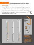
Sabertooth 2x10 RC User’s Guide:
Input Voltage: 6V to 25V (2s to 6s lithium)
Output current: Up to 10A per motor
Peak output current: Up to 15A per motor
Weight: 1.1oz/32 grams
Size: 2.3” x 1.8” x .75”
Sabertooth 2x10 RC is designed for combat robots from 16oz to 12lb, and generalpurpose robots up to 100lb. It controls two motors in mixed or independent modes. Its synchronous regenerative drive allows for high
efficiency operation and recharges your battery when you slow down or reverse. It is internally protected from damage due to
overheating and over-current.
Installation Overview:
Battery connections – The positive (usually red) wire connects to the B+ terminal and the negative (usually black) wire connects to
the B- terminal. Using a polarized mating battery connector such as Deans Ultra is recommended to ensure a reliable connection.
Motor connections – Connect Motor 1 to the M1A and M1B terminals, and Motor 2 to the M2A and M2B terminals.
Fwd/CH1 connector – This connector controls the forward/backwards motion of your robot in Mixed mode, and Motor 1 in
independent mode. It is usually connected to the elevator channel on an R/C receiver.
Turn/CH2 connector - This connector controls the turning motion of your robot in Mixed mode, and Motor 2 in independent mode.
It is usually connected to the aileron channel on an R/C receiver.
Flip connector – This connector is used to reverse the steering if your robot gets flipped upside down. It can connect to either a 0V5V signal for automatic flip correction or an R/C channel (usually channel 5 or 6) for radio-controlled flip correction.
Mounting: Sabertooth 2x10 RC mounts with four 4-40 machine screws (included) on a 1.5” x 2” hole pattern. For best thermal
performance it should be mounted with the bottom aluminum heat spreader connected directly to a metal chassis if possible.
Indicator LEDs: The red Error LED will light to indicate overheating or current limit. The green Status1 LED will glow dimly
when power is applied, and brightly when a radio signal is present. The green Status2 LED will flash out the detected number of
lithium cells when lithium mode is enabled.
Options: All options are set by using the option switches.
Mixing mode: With switch 1 in the UP position, the controller is in mixed mode. Switch 1 in the DOWN
position (as shown) turns mixing mode off. Note that Flip (Switch 4) only affects Motor 2 if mixing mode is
off.
Exponential: If switch 2 is in the UP position the controller will be in exponential mode. This makes the
response less sensitive in the center. This is useful to bring very fast robots under control. If Switch 2 is in the
DOWN position (as shown) exponential is disabled and the response is linear.
Lithium Mode: Switch 3 in the DOWN position (as shown) enables Lithium mode, for use with Lithium
batteries. This will shut the controller down at 3.0 volts per cell, preventing damage to a Lithium battery
pack. The detected cell count is flashed on the Status 2 LED. Switch 3 should be in the UP position when
using NiCd, NiMH or lead-acid batteries.
Flip control: Switch 4 in the UP position sets flip to R/C mode. When R/C mode is set, the bot’s steering
will be reversed if the R/C pulse is 1500us or longer. Switch 4 in the DOWN position (as shown) sets flip to
digital input mode. If you are not using the Flip channel (if your bot is not invertible) set switch 4 to DOWN.
Auto-Calibrate: Switch 5 in the UP sets auto-calibrate mode. In auto-calibrate mode the neutral position is
read at power-up and the endpoints are automatically detected. This maximizes your useful stick travel, and
allows use with pistol-grip transmitters with 70/30 throttles. Switch 5 in the DOWN position always uses
1000us for full reverse, 1500us for stop and 2000us for full forward.
Timeout: Switch 6 in the UP position enables timeout. If no signal is received for 1 second, the controller
turns the motors off. This prevents your bot from driving away if you get interference. If Switch 6 is in the
DOWN position, timeout is disabled and the controller will run at the last commanded speed until a new
command is given. This is useful when running from a microcontroller like a Basic Stamp.
