Download RAGEBriDGE vI.D Revision 20 Feb 2013
Transcript
RageBridge v1.0
Overview
Revision 20 Feb 2013
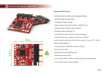
Mounting Dimensions
RageBridge is a motor controller that can drive 2
channels of DC motors from 2 R/C “servo” style PWM
inputs, in forward and reverse with no delay.
RageBridge features optional channel mixing, 3rd
channel direction reversal (“invert”) input, stick travel
calibration, signal-loss failsafe, synchronous rectification
with regenerative braking, constant-current output
mode, and an isolated heat sink plate.
Installation
RageBridge’s isolated heat spreader plate has four
clearance holes for #4 screws (0.130 diameter). The
heat spreader plate may be bolted directly to a metal
chassis for better thermal performance.
Specifications
Voltage Input Range
Continuous Current
Maximum Current
Dimensions
Weight
Inputs
12 – 36v nominal
8 – 50v absolute limits
30A per channel
@ 50% duty cycle, 25°C ambient
Up to 90A per channel
Constant-current mode limited
4.5” x 2” x 0.8” Board only
4.5” x 2.55” x 1.0” With heat sink
3.5oz without wires
Logic Power
2x R/C servo for drive signals
500us to 2500us limits
1100us to 1900us default
1x R/C servo for invert control
1x Mixing switch header
5V @ 150mA maximum
Heat Management
Isolated heat spreader plate
RageBridge may also be mounted without the heat sink
to minimize dimensions. The board itself has 4x #4-40
screws which may be untightened with a 3/32” hex
wrench. Use the following guidelines for best results:
1. Use nonconductive standoffs or spacers to
offset the board from the mounting surface.
2. Insulate the underside using electrical tape or
brush-on insulation compound to prevent stray
metal or wires from shorting.
3. Do not enclose the board in tape, shrink tube,
or sealed cases. Doing so will negatively affect
the thermal performance and reduce
continuous current rating.
1
RageBridge v1.0
Revision 20 Feb 2013
Signal Connection
Power Connection
The IN1, IN2, and IN3 pin headers accept standard
3-pin servo connectors. The ground wire must be
oriented towards the outside of the board. It is
generally black or brown.
Warning: Do not use RageBridge with only a
power supply. The regenerative nature of
RageBridge will cause the motor’s kinetic energy
to be directed into the power supply upon
stopping and can cause high voltage spikes and
damage to both supply and controller. A battery
must be placed between the supply and controller
to absorb this energy if a supply must be used.
Connect IN1 to channel 1 of your radio and IN2 to
channel 2.
If invert control is needed, connect IN3 to a switch
channel on your radio. Else, leave it unconnected.
Power connections to RageBridge are made using
solder terminal holes on the circuit board.
The Mixing switch is enabled if the two MIX pins
are connected via a jumper (not included). If it is
disconnected, the channels are independent.
Use 12 to 16 gauge wire. 14 gauge is recommended.
The heat sink should be dismounted first for easiest
access to the solder terminals. Use a 3/32” hex
wrench to undo the four #4-40 screws mounting
the board to the heat sink.
Both sets of B+ and B- terminals must be
connected to power. The board derives logic
power from the right side as viewed from above.
The voltages may be different between sides
provided neither exceeds the board’s capabilities.
Example 2 channel connection
with mixing header (not included) installed
Range and Direction
By default, signal pulse widths greater than 1500us
is associated with motor terminals 1 (MA1 and
MB1) being more positive in voltage.
Twist and tin the wire prior to soldering them in
the terminals. This prevents frayed wires from
shorting neighboring components. Flush cut the
resulting solder joint to minimize risk of causing
shorts.
Invert status is active if the pulse width on IN3 is
greater than 1500us.
2
RageBridge v1.0
Revision 20 Feb 2013
Stick Calibration
RageBridge’s default pulse width range of 1100us –
1900us can be calibrated to better match your
radio travels. Before beginning, we recommend
that your radio be set up such that stick-up or stickright is an increasing pulse width. This direction is
associated with forward. Disconnect all loads from
the controller first, to prevent accidental
movement.
Example wire installation
To calibrate the controller, use the following
procedure:
Flush cutting the resulting joint to minimize shorting risk
1.
Normal and Failsafe Behavior
2.
3.
4.
5.
Under normal circumstances when the controller is
receiving good signals, the green LED (status) will
strobe every 1 second. The motor drivers are active
and the default neutral behavior is braking.
6.
If either IN1 or IN2 receive an invalid signal, the
controller will enter failsafe mode within 1 second.
The green LED will strobe rapidly, and the motors
will coast freely.
7.
8.
9.
If valid signal is received again, the controller will
enter normal operation within 0.5 seconds
Connect both IN1 and IN2 on the controller to your
receiver. Both channels must be calibrated at once.
Power on your transmitter.
Power on the controller.
Apply full forward stick travels within 2 seconds.
Hold full forward stick travels for 5 seconds.
The green LED will light solid, indicating calibration
mode is active.
Apply full reverse stick travels and hold for least 2
seconds
Release the stick to neutral.
Calibration will automatically exit after 2 seconds of
neutral signal.
The green LED will blink rapidly for 1 second to
indicate successful calibration.
At any point, if the procedure is not followed or
there is a signal error, the calibration mode will
simply exit and the controller will enter either
Normal or Failsafe mode.
3
RageBridge v1.0
Output Current Adjustment
Revision 20 Feb 2013
Warnings
A unique feature of RageBridge is its ability to
output exactly as much current as you limit it to.
This is a departure from generic “smart” current
limiting in which you have no control over when
the controller will cut its output current!
1. Controller will be hot during and after
operation. Do not place controller in
contact with low temperature melting
materials. Do not handle controller
immediately after use.
2. Do not reverse battery polarity. This
controller does NOT have reverse polarity
protection. Reverse polarity damage is NOT
covered under warranty. See the Shipping
and Warranty section on e0designs.com for
more information.
3. Do not cover the controller or wrap it in
insulating materials. Doing so will
compromise the controller’s ability to
dissipate heat and will reduce the
continuous current rating.
4. Do not short the controller or allow
conductive materials to contact the board
directly. The current limit is not guaranteed
to protect against “dead” shorts and board
level shorts.
5. Do not use RageBridge with only a power
supply. The regenerative nature of
RageBridge will cause the motor’s kinetic
energy to be directed into the power supply
upon stopping and can cause high voltage
spikes and damage to both supply and
controller. A battery must be placed
between the supply and controller to
absorb this energy if a supply must be used.
RageBridge will output up to your maximum
current limit and reduce its output voltage just
enough to maintain that current limit if the
demand is higher. This offers protection against
stalled
motors,
over-torquing
actuators,
acceleration-sensitive applications, etc.
To adjust the current limit, turn the Max Current
trim potentiometer to your desired setting using a
nonconductive screwdriver:
The default setting is approximately 50 amps. Use a
DC ammeter connected to the motor output wire
side to verify exact current.
The accuracy of the current limit is strongly
dependent on motor inductance; for typical iron
core motors, the accuracy is ± 2-5 amps.
4


