1
BLCDN-6M12LT-2RFID-S-8XSG-PD
10 Parameters
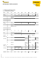
10.1 DeviceNet™-Parameters
Gateway parameters (fieldbus communication)
The module provides the following parameters to configure the DeviceNet™-communication.
The parameters are described in module-specific EDS-files which allow text-based parameterization in EDS-interpreting configuration tools like
RSNetworx from Rockwell Automation, for example.
For a parameterization via Class Instance Attribute (C - I - A), please find the necessary information in brackets (hexadecimal format).
Parameter
MAC-ID (03 - 01 - 01)
Baud rate
(03 - 01 - 02)
AutoBaud
(03 - 01 - 64)
on I/O cntcn timeout
(64 - 02 - 73)
BUS OFF irtp
(03 - 01 - 03)
* default setting
Description
0 to 63
0 = 125 kbps *
1 = 250 kbps
2 = 500 kbps
0 = disable
1 = enable *
Defines the output behavior in case of I/O connection timeout:
0 = switch outputs faulted *
1 = switch outputs off
2 = hold outputs
0 = holf CAN chip in BUS OFF state *
1 = reset CAN chip
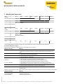
10.2 RFID-S - Parameters
Parameter
RFID-S Bypass Ch1 (in ms)
(7C - 1 - 73) and
RFID-S Bypass Ch2 (in ms)
(7C - 1 - 43)
Description
Bypass time of the transceiver in steps of 4 milliseconds: Values from 0 = 0 ms* to 255 = 1020 ms
Please maintain the default setting “= 0“ of this parameter if the system startup is done without the error
message "Dwell time of the Tag in the detection area was not long enough for successful command processing.". Check if the application makes it possible to set the recommended minimum distances, to reduce the speed or the transferred data amount. The information about the recommended and the maximum distances can be found in the Installation manual D101583.pdf for the RFID-system in the chapter "operating data“. If you are not able to respect the required distances or if the error is still sent due to
external influences even if these distances are respected, this parameter has to be set to an adequate
value.
* default setting
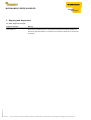
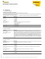
10.3 8XSG - Parameters
Description
The input signal is inverted (bit 0 = channel 0 to bit 7 = channel 7).
0 = normal *
1 = inverted
8XSG-PD output auto recovery
The outputs (bit 0 = channel 0 to bit 7 = channel 7) switch on automatically after an overload.
(75 - 1 - 85)
0 = active *
1 = inactive
8XSG-PD output re-triggered recovery The outputs (bit 0 = channel 0 to bit 7 = channel 7) have to be retriggered in case of an overload.
(75 - 1 - 89)
0 = inactive *
1 = active
8XSG-PD enable output
Activates the output at this channel (bit 0 = channel 0 to bit 7 = channel 7).
(75 - 1 - 8B)
0 = inactive *
1 = active
8XSG-PD enable 2.5ms input filtering Sets the input filter from 0.25 ms to 2.5 ms (bit 0 = channel 0 to bit 7 = channel 7).
(75 - 1 - 8F)
0 = disabled *
1 = enabled
* default setting
Edition • 2011-3-15
Parameter
8XSG-PD invert input
(75 - 1 - 7F)
17 / 32011
Hans Turck GmbH & Co.KG ñ D-45472 Mülheim an der Ruhr ñ Witzlebenstraße 7 ñ Tel. 0208 4952-0 ñ Fax 0208 4952-264 ñ [email protected] ñ www.turck.com