1
PT330 Series
System Board
User’s Manual
A13010102
Copyright
This publication contains information that is protected by copyright. No part of it
may be reproduced in any form or by any means or used to make any transformation/adaptation without the prior written permission from the copyright holders.
This publication is provided for informational purposes only. The manufacturer
makes no representations or warranties with respect to the contents or use
of this manual and specifically disclaims any express or implied warranties of
merchantability or fitness for any particular purpose. The user will assume the
entire risk of the use or the results of the use of this document. Further, the
manufacturer reserves the right to revise this publication and make changes to
its contents at any time, without obligation to notify any person or entity of such
revisions or changes.
© 2011. All Rights Reserved.
Trademarks
All trademarks and registered trademarks of products appearing in this manual
are the properties of their respective holders.
FCC and DOC Statement on Class B
This equipment has been tested and found to comply with the limits for a Class B
digital device, pursuant to Part 15 of the FCC rules. These limits are designed to
provide reasonable protection against harmful interference when the equipment
is operated in a residential installation. This equipment generates, uses and can
radiate radio frequency energy and, if not installed and used in accordance with
the instruction manual, may cause harmful interference to radio communications.
However, there is no guarantee that interference will not occur in a particular
installation. If this equipment does cause harmful interference to radio or television reception, which can be determined by turning the equipment off and on,
the user is encouraged to try to correct the interference by one or more of the
following measures:
•
•
•
•
Reorient or relocate the receiving antenna.
Increase the separation between the equipment and the receiver.
Connect the equipment into an outlet on a circuit different from that to which
the receiver is connected.
Consult the dealer or an experienced radio TV technician for help.
Notice:
1. The changes or modifications not expressly approved by the party responsible
for compliance could void the user’s authority to operate the equipment.
2. Shielded interface cables must be used in order to comply with the emission
limits.
1
Introduction
Table of Contents
Copyright. .......................................................................................... 2
Trademarks......................................................................................... 2
FCC and DOC Statement on Class B............................................... 3
About this Manual.............................................................................. 7
Warranty
........................................................................................... 7
Static Electricity Precautions.............................................................. 8
Safety Measures.................................................................................. 8
About the Package............................................................................. 9
Before Using the System Board......................................................... 9
Chapter 1 - Introduction................................................................. 10
Specifications................................................................................. 10
Features . ..................................................................................... 12
Chapter 2 - Hardware Installation................................................... 15
System Board Layout..................................................................... 15
System Memory............................................................................ 16
Installing the DIMM Module........................................................ 18
CPU............................................................................................. 20
Installing the CPU..................................................................... 21
Installing the Fan and Heat Sink................................................. 25
Jumper Settings............................................................................. 27
Clear CMOS Data...................................................................... 27
PS/2 Power Select..................................................................... 28
USB Power Select...................................................................... 29
Power-on Select........................................................................ 30
Rear Panel I/O Ports. .................................................................... 31
PS/2 Mouse and PS/2 Keyboard Ports.......................................... 32
COM (Serial) Ports.................................................................... 33
VGA Port.................................................................................. 34
DVI-I Port................................................................................ 35
USB Ports................................................................................ 36
RJ45 LAN Port.......................................................................... 38
Audio ..................................................................................... 39
4
Introduction
1
I/O Connectors............................................................................. 40
CD-in Internal Audio Connector.................................................. 40
S/PDIF Connector...................................................................... 41
Digital I/O Connector................................................................. 42
SATA (Serial ATA) Ports............................................................. 43
FDD (Floppy Disk Drive) Connector............................................. 44
Cooling Fan Connectors.............................................................. 45
Chassis Instrusion Connector...................................................... 46
Power Connectors..................................................................... 47
Standby Power LED................................................................... 48
Front Panel Connectors.............................................................. 49
Expansion Slots........................................................................ 50
Battery.................................................................................... 51
Chapter 3 - BIOS Setup................................................................... 52
Overview............................................................................................................... 52
AMI BIOS Setup Utility.................................................................. 54
Main........................................................................................ 54
Advanced................................................................................. 55
PCIPnP..................................................................................... 78
Boot........................................................................................ 80
Security................................................................................... 86
Chipset.................................................................................... 89
Exit......................................................................................... 94
Updating the BIOS. ....................................................................... 97
Chapter 4 - Supported Software
.................................................... 98
Intel Chipset Software Installation Utility..................................................... 99
Microsoft DirectX 9.0C Driver..................................................................... 101
Microsoft .NET Framework 3.5..................................................................... 102
Intel Graphics Drivers...................................................................................... 104
Audio Drivers..................................................................................................... 106
Realtek LAN Drivers........................................................................................ 107
Intel LAN Drivers............................................................................................. 108
Intel Management Engine Interface............................................................... 110
MyGuard Hardware Monitor......................................................................... 112
Adobe Acrobat Reader 9.3............................................................................. 114
Infineon TPM Driver and Tool (optional)..................................................... 116
5
1
Introduction
Chapter 5 - RAID
......................................................................... 121
RAID Levels........................................................................................................ 121
Settings................................................................................................................. 122
Chapter 6 - Intel AMT Settings
.................................................... 126
Overview............................................................................................................. 126
Enable Intel® AMT in the AMI BIOS............................................................. 127
Enable Intel® AMT in the Intel® Management Engine BIOS
Extension (MEBX) Screen............................................................................... 130
Appendix A - NLITE and AHCI Installation Guide........................ 161
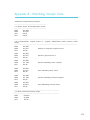
Appendix B - Watchdog Sample Code.......................................... 173
Appendix C - Troubleshooting....................................................... 174
6
Introduction
1
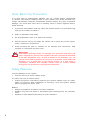
About this Manual
An electronic file of this manual is included in the CD. To view the user’s manual
in the CD, insert the CD into a CD-ROM drive. The autorun screen (Main Board
Utility CD) will appear. Click “User’s Manual” on the main menu.
Warranty
1. Warranty does not cover damages or failures that arised from misuse of the
product, inability to use the product, unauthorized replacement or alteration
of components and product specifications.
2. The warranty is void if the product has been subjected to physical abuse,
improper installation, modification, accidents or unauthorized repair of the
product.
3. Unless otherwise instructed in this user’s manual, the user may not, under
any circumstances, attempt to perform service, adjustments or repairs on the
product, whether in or out of warranty. It must be returned to the purchase
point, factory or authorized service agency for all such work.
4. We will not be liable for any indirect, special, incidental or consequencial
damages to the product that has been modified or altered.
7
1
Introduction
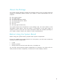
Static Electricity Precautions
It is quite easy to inadvertently damage your PC, system board, components
or devices even before installing them in your system unit. Static electrical discharge can damage computer components without causing any signs of physical
damage. You must take extra care in handling them to ensure against electrostatic build-up.
1. To prevent electrostatic build-up, leave the system board in its anti-static bag
until you are ready to install it.
2. Wear an antistatic wrist strap.
3. Do all preparation work on a static-free surface.
4. Hold the device only by its edges. Be careful not to touch any of the components, contacts or connections.
5. Avoid touching the pins or contacts on all modules and connectors. Hold
modules or connectors by their ends.
Important:
Electrostatic discharge (ESD) can damage your processor, disk drive and
other components. Perform the upgrade instruction procedures described
at an ESD workstation only. If such a station is not available, you can
provide some ESD protection by wearing an antistatic wrist strap and
attaching it to a metal part of the system chassis. If a wrist strap is
unavailable, establish and maintain contact with the system chassis
throughout any procedures requiring ESD protection.
Safety Measures
To avoid damage to the system:
• Use the correct AC input voltage range.
To reduce the risk of electric shock:
• Unplug the power cord before removing the system chassis cover for installation or servicing. After installation or servicing, cover the system chassis
before plugging the power cord.
Battery:
• Danger of explosion if battery incorrectly replaced.
• Replace only with the same or equivalent type recommend by the manufacturer.
• Dispose of used batteries according to local ordinance.
8
Introduction
1
About the Package
The system board package contains the following items. If any of these items are
missing or damaged, please contact your dealer or sales representative for assistance.
One
Two
Two
Two
One
One
One
system board
USB cables
Serial ATA data cables
Serial ATA power cables
I/O shield
CD
QR (Quick Reference)
The system board and accessories in the package may not come similar to the
information listed above. This may differ in accordance to the sales region or
models in which it was sold. For more information about the standard package in
your region, please contact your dealer or sales representative.
Before Using the System Board
Before using the system board, prepare basic system components.
If you are installing the system board in a new system, you will need at least the
following internal components.
•
•
•
A CPU
Memory module
Storage devices such as hard disk drive, CD-ROM, etc.
You will also need external system peripherals you intend to use which will normally include at least a keyboard, a mouse and a video display monitor.
9
1
Introduction
Chapter 1 - Introduction
Specifications
Processor
10
•LGA 1156 socket for:
- Intel® CoreTM i7-860 2.80GHz/8M
- Intel® Core™ i5-750 2.66GHz/8M
- Intel® CoreTM i5-660 3.33GHz/4M
- Intel® CoreTM i3-540 3.06GHz/4M
- Intel® Pentium® G6950 2.80GHz/3M
Chipset
•Intel® Q57 PCH (Platform Controller Hub)
System Memory
•Four 240-pin DDR3 DIMM sockets
•Supports DDR3 1066/1333MHz
•Supports maximum memory bandwidth of 21GB/s in dualchannel mode when using DDR3 1333MHz
• Supports dual channel memory interface
• Supports up to 16GB system memory
Expansion Slots
•1 PCI Express x16 slot (PCIe 2.0)
•1 PCI Express x4 slot (PCIe 1.0)
•2 PCI slots (PCI 2.3)
Graphics
•Intel® HD Graphics
•VGA display resolution up to 2048x1536
•Supports 3D, 2D and video capabilities
Note: Both Intel® CoreTM i7-860 and CoreTM i5-750 CPUs do
not support integrated graphics.
Audio
•Realtek ALC262 2-channel High Definition Audio
•Two 24-bit stereo DACs and three 20-bit stereo ADCs
•S/PDIF audio interface
LAN
•One Realtek RTL8111DL PCI Express Gigabit Ethernet controller
•One Intel W82578DM with iAMT6.0 Gigabit Ethernet PHY
•Supports 10Mbps, 100Mbps and 1Gbps data transmission
•IEEE 802.3 (10/100Mbps) and IEEE 802.3ab (1Gbps) compliant
Serial ATA
•6 Serial ATA ports compliant with SATA 1.0 specification
•SATA speed up to 3Gb/s (SATA 2.0)
•Supports RAID 0/1/5/10
INTEL ACTIVE
MANAGEMENT
TECHNOLOGY
(AMT)
•Supports iAMT6.0
•Out-of-band system access
•Remote troubleshooting and recovery
•Hardware-based agent presence checking
•Proactive alerting
•Remote hardware and software asset tracking
Introduction
TPM - TRUSTED
PLATFORM
MODULE
(optional)
•Provides a Trusted PC for secure transactions
•Provides software license protection, enforcement and password protection
Rear Panel I/O
Ports
•
•
•
•
•
•
•
•
1 mini-DIN-6 PS/2 mouse port
1 mini-DIN-6 PS/2 keyboard port
2 DB-9 RS232 serial ports
1 DB-15 VGA port
1 DVI-I port (DVI-D signal only)
2 RJ45 LAN ports
4 USB 2.0/1.1 ports
Mic-in, line-in and line-out
I/O Connectors
•
•
•
•
•
•
•
•
•
•
•
•
4
1
1
1
1
6
1
1
1
1
1
2
BIOS
•AMI BIOS
•64Mbit SPI BIOS
Energy Efficient
Design
•ACPI v3.0 specification
• System Power Management
• Wake-On-Events include:
- Wake-On-PS/2 Keyboard/Mouse
- Wake-On-USB Keyboard/Mouse
- Wake-On-LAN
• AC power failure recovery
Damage Free
Intelligence
•Monitors CPU/system temperature and overheat alarm
•Monitors VCORE/5V/3.3V/V_DIMM/12V/5VSB voltages and
failure alarm
•Monitors CPU/system fan speed and failure alarm
•Read back capability that displays temperature, voltage and
fan speed
•Watchdog timer function
Temperature
•0oC to 60oC
Humidity
•10% to 90%
PCB
•microATX form factor
•244mm (9.6”) x 244mm (9.6”)
1
connectors for 8 external USB 2.0/1.1 ports
8-bit Digital I/O connector
front audio connector for line-out and mic-in jacks
CD-in connector
S/PDIF connector
Serial ATA ports
FDD connector
24-pin ATX power connector
8-pin 12V power connector
chassis intrusion connector
front panel connector
fan connectors
11
1
Introduction
Features
Watchdog Timer
The Watchdog Timer function allows your application to regularly “clear” the system at the set time interval. If the system hangs or fails to function, it will reset
at the set time interval so that your system will continue to operate.
DDR3
DDR3 delivers increased system bandwidth and improved performance. It offers
peak data transfer rate of up to 21 Gb/s bandwidth. The advantages of DDR3
are its higher bandwidth and its increase in performance at a lower power than
DDR2.
Graphics
The Intel Clarkdale CPU comes integrated with the Graphics Processing Unit delivering exceptional 3D, 2D and video capabilities. It supports VGA and DVI interfaces.
PCI Express
PCI Express is a high bandwidth I/O infrastructure that possesses the ability to
scale speeds by forming multiple lanes. The x4 PCI Express lane supports transfer rate of 1 Gigabyte per second. The PCI Express architecture also provides a
high performance graphics infrastructure by enhancing the capability of a x16 PCI
Express lane to provide 4 Gigabytes per second transfer rate.
Intel Active Management Technology (AMT)
Intel Active Management Technology (Intel® AMT) allows remote access and management of networked systems even while PCs are powered off, remotely repair
systems after OS failures and has the capability to remotely update all systems
with the latest security software.
Audio
The Realtek ALC262 audio codec provides 2-channel High Definition audio output.
S/PDIF
S/PDIF is a standard audio file transfer format that transfers digital audio signals to a device without having to be converted first to an analog format. This
prevents the quality of the audio signal from degrading whenever it is converted
to analog. S/PDIF is usually found on digital audio equipment such as a DAT
machine or audio processing device. The S/PDIF connector on the system board
sends surround sound and 3D audio signal outputs to amplifiers and speakers
and to digital recording devices like CD recorders.
12
Introduction
1
Serial ATA
Serial ATA is a storage interface that is compliant with SATA 1.0a specification.
With speed of up to 3Gbps, it improves hard drive performance faster than the
standard parallel ATA whose data transfer rate is 100MB/s. It supports RAID
0/1/5/10.
Gigabit LAN
The Intel W82578DM PHY and Realtek RTL8111DL PCI Express Gigabit controllers
support up to 1Gbps data transmission.
USB
The system board supports USB 2.0 and USB 1.1 ports. USB 1.1 supports 12Mb/
second bandwidth while USB 2.0 supports 480Mb/second bandwidth providing a
marked improvement in device transfer speeds between your computer and a
wide range of simultaneously accessible external Plug and Play peripherals.
Wake-On-LAN
This feature allows the network to remotely wake up a Soft Power Down (SoftOff) PC. It is supported via the onboard LAN port or via a PCI LAN card that uses
the PCI PME (Power Management Event) signal. However, if your system is in the
Suspend mode, you can power-on the system only through an IRQ or DMA interrupt.
Important:
The 5V_standby power source of your power supply must support
≥720mA.
Wake-On-PS/2
This function allows you to use the PS/2 keyboard or PS/2 mouse to power-on
the system.
Important:
The 5V_standby power source of your power supply must support
≥720mA.
Wake-On-USB
This function allows you to use a USB keyboard or USB mouse to wake up a system from the S3 (STR - Suspend To RAM) state.
Important:
If you are using the Wake-On-USB Keyboard/Mouse function for 2 USB
ports, the 5V_standby power source of your power supply must support
≥1.5A. For 3 or more USB ports, the 5V_standby power source of your
power supply must support ≥2A.
13
1
Introduction
ACPI STR
The system board is designed to meet the ACPI (Advanced Configuration and
Power Interface) specification. ACPI has energy saving features that enables PCs
to implement Power Management and Plug-and-Play with operating systems that
support OS Direct Power Management. ACPI when enabled in the Power Management Setup will allow you to use the Suspend to RAM function.
With the Suspend to RAM function enabled, you can power-off the system at
once by pressing the power button or selecting “Standby” when you shut down
Windows® without having to go through the sometimes tiresome process of
closing files, applications and operating system. This is because the system is
capable of storing all programs and data files during the entire operating session
into RAM (Random Access Memory) when it powers-off. The operating session will
resume exactly where you left off the next time you power-on the system.
Important:
The 5V_standby power source of your power supply must support
≥720mA.
Power Failure Recovery
When power returns after an AC power failure, you may choose to either poweron the system manually or let the system power-on automatically.
14
2
Hardware Installation
Chapter 2 - Hardware Installation
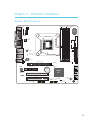
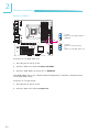
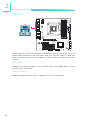
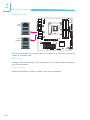
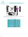
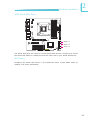
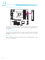
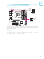
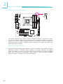
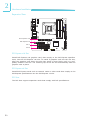
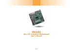
System Board Layout
CPU fan
1
Mouse
K/B
DDR3-2
DDR3-4
DDR3-1
DDR3-3
1
Chassis
intrusion
1
Fintek
F71879F
12V power
VGA
DVI -I
FDD
PS/2 power
select (JP4)
12
LGA 1156
Chrontel
CH7318C
DVI-I port
(DVI-D signal only)
COM 2
COM 1
1
DIO
2
1
1 2
33 34
19
LAN 1 (Intel)
USB 1
USB 0
Intel
W82578DM
LAN 2
(Realtek)
USB 3
USB 2
Standby
Power LED
ATX power
1
USB 0-3 power
select (JP2)
Realtek
RTL8111DL
Mic-in
Line-in
Line-out
1
CD-IN
Realtek
ALC262
Power-on
select (JP6)
PCI Express x16
1
PCI Express x4
10
9
Intel
Q57
PCI 1
Front audio
1
S/PDIF
1
System
fan
SATA 4
SATA 5
USB 10-11 USB 8-9
1
1
SATA 2
SATA 3
PCI 2
USB 8-11 power
select (JP7)
13
1
SATA 0
SATA 1
Battery
2
1
24
12
1
1
Clear CMOS
USB 4-7 power
(JP1)
select (JP3)
USB 6-7 USB 4-5
1
1
SPI Flash
BIOS
1
Front
panel
11
1
12
2
15
2
Hardware Installation
Important:
Electrostatic discharge (ESD) can damage your system board, processor,
disk drives, add-in boards, and other components. Perform the upgrade
instruction procedures described at an ESD workstation only. If such a
station is not available, you can provide some ESD protection by wearing
an antistatic wrist strap and attaching it to a metal part of the system
chassis. If a wrist strap is unavailable, establish and maintain contact
with the system chassis throughout any procedures requiring ESD protection.
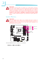
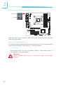
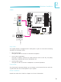
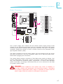
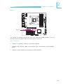
System Memory
Important:
When the Standby Power LED lit red, it indicates that there is power on
the system board. Power-off the PC then unplug the power cord prior to
installing any devices. Failure to do so will cause severe damage to the
motherboard and components.
DDR3-2
DDR3-1
2
1
DDR3-4
DDR3-3
Standby
Power LED
The four DIMM sockets are divided into 2 channels:
Channel A - DIMM 1 and DIMM 2
Channel B - DIMM 3 and DIMM 4
16
Channel A
Channel B
Hardware Installation
2
The system board supports the following memory interface.
Single Channel (SC)
Data will be accessed in chunks of 64 bits from the memory channels.
Dual Channel (DC)
Data will be accessed in chunks of 128 bits from the memory channels. Dual
channel provides better system performance because it doubles the data transfer
rate.
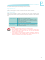
Single Channel
DIMMs are on the same channel.
DIMMs in a channel can be identical or completely different. However, we highly recommend
using identical DIMMs.
Not all slots need to be populated.
Dual Channel
DIMMs of the same memory configuration are
on different channels.
Important:
1. You can populate either Channel A or Channel B first.
2. When installing a DIMM in Channel A or Channel B, always populate the socket that is farthest the CPU. This will mean populating
DDR3-1 and/or DDR3-3 first.
3. If you intend to use dual channel, the same rule applies - always the
socket farthest the CPU. Populate DDR3-1 and/or DDR3-3 first; not
DDR3-1 and DDR3-4 and not DDR3-3 and DDR3-2.
17
2
Hardware Installation
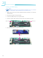
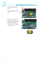
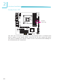
Installing the DIMM Module
Note:
The system board used in the following illustrations may not resemble
the actual board. These illustrations are for reference only.
1. Make sure the PC and all other peripheral devices connected to it has been
powered down.
2. Disconnect all power cords and cables.
3. Locate the DIMM socket on the system board.
4. Push the “ejector tabs” which are at the ends of the socket to the side.
Ejector tab
Ejector tab
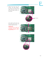
5. Note how the module is keyed to the socket.
Notch
Key
18
Hardware Installation
2
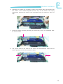
6. Grasping the module by its edges, position the module above the socket with
the “notch” in the module aligned with the “key” on the socket. The keying
mechanism ensures the module can be plugged into the socket in only one
way.
7. Seat the module vertically, pressing it down firmly until it is completely seated in the socket.
8. The ejector tabs at the ends of the socket will automatically snap into the
locked position to hold the module in place.
19
2
Hardware Installation
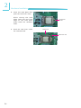
CPU
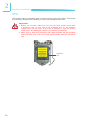
The system board is equipped with a surface mount LGA 1156 socket. This socket
is exclusively designed for installing a LGA 1156 packaged Intel CPU.
Important:
1. Before you proceed, make sure (1) the LGA 1156 socket comes with
a protective cap, (2) the cap is not damaged and (3) the socket’s
contact pins are not bent. If the cap is missing or the cap and/or
contact pins are damaged, contact your dealer immediately.
2. Make sure to keep the protective cap. RMA requests will be accepted
and processed only if the LGA 1156 socket comes with the protective
cap.
Protective
cap
20
Hardware Installation
2
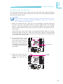
Installing the CPU
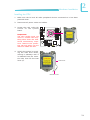
1. Make sure the PC and all other peripheral devices connected to it has been
powered down.
2. Disconnect all power cords and cables.
3. Locate the LGA 1156 CPU
socket on the system
board.
2
1
Important:
The CPU socket must not
come in contact with anything other than the CPU.
Avoid unnecessary exposure. Remove the protective cap only when you are
about to install the CPU.
4. Unlock the socket by pushing the load lever down,
moving it sideways until it
is released from the retention tab; then lift the load
lever up.
Load lever
Retention tab
21
2
Hardware Installation
5. Lifting the load lever will at
the same time lift the load
plate.
Lift the load lever up to
the angle shown on the
photo.
Load lever
Load
plate
6. Remove the protective cap
from the CPU socket. The
cap is used to protect the
CPU socket against dust
and harmful particles. Remove the protective cap
only when you are about
to install the CPU.
Protective cap
22
Hardware Installation
2
7. Insert the CPU into the
socket. The gold triangular mark on the CPU must
align with the corner of
the CPU socket shown on
the photo.
Gold triangular
mark
The CPU’s notch will at
the same time fit into the
socket’s alignment key.
Alignment key
Important:
The CPU will fit in only one
orientation and can easily
be inserted without exerting any force.
Alignment key
23
2
Hardware Installation
8. Close the load plate then
push the load lever down.
While closing the load
plate, make sure the front
edge of the load plate
slides under the retention
knob.
9. Hook the load lever under
the retention tab.
Retention
knob
Load lever
Retention tab
24
Hardware Installation
2
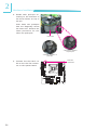
Installing the Fan and Heat Sink
The CPU must be kept cool by using a CPU fan with heat sink. Without sufficient
air circulation across the CPU and heat sink, the CPU will overheat damaging both
the CPU and system board.
Note:
A boxed Intel® processor already includes the CPU fan and heat sink assembly. If your CPU was purchased separately, make sure to only use
Intel®-certified fan and heat sink.
1. Before you install the fan / heat sink, you must apply a thermal paste onto
the top of the CPU. The thermal paste is usually supplied when you purchase
the fan / heat sink assembly. Do not spread the paste all over the surface.
When you later place the heat sink on top of the CPU, the compound will disperse evenly.
Some heat sinks come with a patch of pre-applied thermal paste. Do not apply thermal paste if the fan / heat sink already has a patch of thermal paste
on its underside. Peel the strip that covers the paste before you place the fan
/ heat sink on top of the CPU.
2. Place the heat sink on top
of the CPU. The 4 pushpins around the heat sink,
which are used to secure
the heat sink onto the system board, must match the
4 mounting holes around
the socket.
3. Orient the heat sink such
that the CPU fan’s cable is
nearest the CPU fan connector.
2
1
Mounting hole
CPU fan
connector
2
1
25
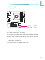
2
Hardware Installation
4. Rotate each push-pin according to the direction of
the arrow shown on top of
the pin.
Push down two pushpins
that are diagonally across
the heat sink. Perform the
same procedure for the
other two push-pins.
Heat sink
“Unlocked” position
of push-pin
“Locked” position of
push-pin
CPU fan
connector
5. Connect the CPU fan’s cable to the CPU fan connector on the system board.
2
1
26
Hardware Installation
2
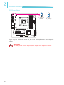
Jumper Settings
Clear CMOS Data
2
1
3
JP1
2 1
1-2 On: Normal
(default)
3 2 1
2-3 On:
Clear CMOS Data
If you encounter the following,
a) CMOS data becomes corrupted.
b) You forgot the supervisor or user password.
you can reconfigure the system with the default values stored in the ROM BIOS.
To load the default values stored in the ROM BIOS, please follow the steps below.
1. Power-off the system and unplug the power cord.
2. Set JP1 pins 2 and 3 to On. Wait for a few seconds and set JP1 back to its
default setting, pins 1 and 2 On.
3. Now plug the power cord and power-on the system.
27
2
Hardware Installation
PS/2 Power Select
JP4
1
1
2
2
3
3
1-2 On: 5V
(default)
2-3 On:
5V_standby
2
1
JP4 is used to select the power of the PS/2 keyboard/mouse port. Selecting
5V_standby will allow you to use a PS/2 keyboard or PS/2 mouse to wake up the
system.
Important:
The 5VSB power source of your power supply must support ≥720mA.
28
Hardware Installation
2
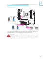
USB Power Select
2
1
USB 0-3
(JP2)
1
1
2
2
3
3
1-2 On: 5V
(default)
2-3 On:
5V_standby
USB 8-11
(JP7)
1
1
2
2
3
3
1-2 On: 5V
(default)
2-3 On:
5V_standby
USB 4-7
(JP3)
3
2 1
1-2 On: 5V
(default)
3 2 1
2-3 On:
5V_standby
These jumpers are used to select the power of the USB ports. Selecting 5V_
standby will allow you to use a USB device to wake up the system.
Important:
If you are using the Wake-On-USB Keyboard/Mouse function for 2 USB
ports, the 5V_standby power source of your power supply must support
≥1.5A. For 3 or more USB ports, the 5V_standby power source of your
power supply must support ≥2A.
29
2
Hardware Installation
Power-on Select
2
1
JP6
1 1-2 On:
2 Power-on via power button
(default) 3
1
2
3
2-3 On:
Power-on via AC power;
or
Power-on via WOL after G3
To power-on via WOL after G3:
1. Set JP6 pins 2 and 3 to On.
2. Set the “After G3” field to Power Off/WOL.
3. Set the “GbE Wake Up From S5” to Enabled.
The BIOS fields are in the “South Bridge Configuration” submenu (Chipset menu)
of the AMI BIOS utility.
To power-on via AC Power:
1. Set JP6 pins 2 and 3 to On.
2. Set the “After G3” field to Power On.
30
Hardware Installation
2
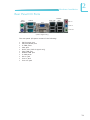
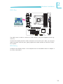
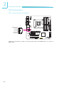
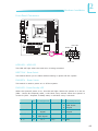
Rear Panel I/O Ports
PS/2
Mouse
COM 2
Intel LAN
Realtek
LAN
VGA
Mic-in
Line-in
Line-out
PS/2 K/B
COM 1
DVI-I
USB 0-1
(DVI-D signal only)
USB 2-3
The rear panel I/O ports consist of the following:
•
•
•
•
•
•
•
•
•
•
•
PS/2 mouse port
PS/2 keyboard port
2 COM ports
VGA port
DVI-I port (DVI-D signal only)
Intel LAN port
Realtek LAN port
4 USB ports
Mic-in jack
Line-in jack
Line-out jack
31
2
Hardware Installation
PS/2 Mouse and PS/2 Keyboard Ports
PS/2 Mouse
PS/2 KB
2
1
These ports are used to connect a PS/2 mouse and a PS/2 keyboard. The PS/2
mouse port uses IRQ12.
Wake-On-PS/2 Keyboard/Mouse
The Wake-On-PS/2 Keyboard/Mouse function allows you to use the PS/2 keyboard
or PS/2 mouse to power-on the system. To use this function:
•
Jumper Setting
JP4 must be set to “2-3 On: 5V_standby”. Refer to “PS/2 Power Select” in
this chapter for more information.
Important:
The 5V_standby power source of your power supply must support
≥720mA.
32
Hardware Installation
2
COM (Serial) Ports
COM 2
COM 1
2
1
The serial ports are RS232 asynchronous communication ports with 16C550Acompatible UARTs that can be used with modems, serial printers, remote display
terminals, and other serial devices.
BIOS Setting
Configure the serial ports in the Advanced menu of the BIOS. Refer to chapter 3
for more information.
33
2
Hardware Installation
VGA Port
VGA
2
1
The VGA port is used for connecting a VGA monitor. Connect the monitor’s 15-pin
D-shell cable connector to the VGA port. After you plug the monitor’s cable connector into the VGA port, gently tighten the cable screws to hold the connector
in place.
BIOS Setting
Configure the onboard graphics in the Chipset menu of the BIOS. Refer to chapter 3 for more information.
Driver Installation
Install the graphics driver. Refer to chapter 4 for more information.
34
Hardware Installation
2
DVI-I Port
2
1
DVI-I
(DVI-D signal only)
The DVI-I port is used to connect an LCD monitor. This port supports DVI-D signal only.
Connect the display device’s cable connector to the DVI-I port. After you plug the
cable connector into the port, gently tighten the cable screws to hold the connector in place.
BIOS Setting
Configure the display device in the Chipset menu of the BIOS. Refer to chapter 3
for more information.
35
2
Hardware Installation
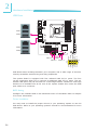
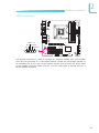
USB Ports
2
1
USB 1
USB 0
USB 3
USB 10-11 USB 6-7
USB 4-5
10
2
1
9
VCC
-Data
+Data
GND
Key
USB 8-9
+Data
GND
N. C.
VCC
-Data
USB 2
USB allows data exchange between your computer and a wide range of simultaneously accessible external Plug and Play peripherals.
The system board is equipped with four onboard USB 2.0/1.1 ports. The four
10-pin connectors allow you to connect 8 additional USB 2.0/1.1 ports. The additional USB ports may be mounted on a card-edge bracket. Install the card-edge
bracket to an available slot at the rear of the system chassis then insert the USB
port cables to a connector.
BIOS Setting
Configure the onboard USB in the Advanced menu of the BIOS. Refer to chapter
3 for more information.
Driver Installation
You may need to install the proper drivers in your operating system to use the
USB device. Refer to your operating system’s manual or documentation for more
information.
36
Hardware Installation
2
Wake-On-USB Keyboard/Mouse
The Wake-On-USB Keyboard/Mouse function allows you to use a USB keyboard or
USB mouse to wake up a system from the S3 (STR - Suspend To RAM) state. To
use this function:
•
Jumper Setting
JP2, JP3 and/or JP7 must be set to “2-3 On: 5V_standby”. Refer to “USB
Power Select” in this chapter for more information.
Important:
If you are using the Wake-On-USB Keyboard/Mouse function for 2 USB
ports, the 5V_standby power source of your power supply must support
≥1.5A. For 3 or more USB ports, the 5V_standby power source of your
power supply must support ≥2A.
37
2
Hardware Installation
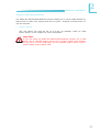
RJ45 LAN Ports
LAN 1
(Intel)
2
1
LAN 2
(Realtek)
The LAN ports allow the system board to connect to a local area network by
means of a network hub.
BIOS Setting
Configure the onboard LAN in the Chipset menu of the BIOS. Refer to chapter 3
for more information.
Driver Installation
Install the LAN drivers. Refer to chapter 4 for more information.
38
Hardware Installation
2
Audio
Rear audio
Mic-in
2
1
Line-in
Presence Signal
Mic2-JD
Key
Line2-JD
GND
Line-out
10
9
Mic2-L
Mic2-R
Line2-R
Front_IO_Sense
Line2-L
Front 2
audio 1
Rear Audio
The system board is equipped with 3 audio jacks. A jack is a one-hole connecting
interface for inserting a plug.
•
Mic-in Jack (Pink)
This jack is used to connect an external microphone.
•
Line-in Jack (Light Blue)
This jack is used to connect any audio devices such as Hi-fi set, CD player,
tape player, AM/FM radio tuner, synthesizer, etc.
•
Line-out Jack (Lime)
This jack is used to connect a headphone or external speakers.
Front Audio
The front audio connector allows you to connect to the second line-out and micin jacks that are at the front panel of your system.
Driver Installation
Install the audio driver. Refer to chapter 4 for more information.
39
2
Hardware Installation
I/O Connectors
CD-in Internal Audio Connector
2
1
Right audio
channel
4
Ground
Ground
Left audio
channel
1
The CD-in connector is used to receive audio from a CD-ROM drive, TV tuner or
MPEG card.
40
Hardware Installation
2
S/PDIF Connector
2
1
SPDIF out
Key Ground
+5V
1
SPDIF in
5
The S/PDIF connector is used to connect an external S/PDIF port. Your S/PDIF
port may be mounted on a card-edge bracket. Install the card-edge bracket to
an available slot at the rear of the system chassis then connect the audio cable
to the S/PDIF connector. Make sure pin 1 of the audio cable is aligned with pin 1
of the S/PDIF connector.
41
2
Hardware Installation
Digital I/O Connector
12
2
1
19
The Digital I/O connector provides powering-on function to an external device
that is connected to this connector.
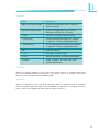
Digital I/O Connector
42
Pins
Function
Pins
Function
1
GND
2
+12V
3
DIO7
4
+12V
5
DIO6
6
GND
7
DIO5
8
VCC
9
DIO4
10
VCC
11
DIO3
12
GND
13
DIO2
14
V_5P0_STBY
15
DIO1
16
V_5P0_STBY
17
DIO0
18
GND
19
GND
Hardware Installation
2
SATA (Serial ATA) Ports
2
1
SATA 0-1
SATA 2-3
SATA 4-5
The Serial ATA ports are used to connect Serial ATA devices. Connect one end of
the Serial ATA cable to a SATA port and the other end to your Serial ATA device.
BIOS Setting
Configure the Serial ATA drives in the Advanced menu of the BIOS. Refer to
chapter 3 for more information.
43
2
Hardware Installation
FDD (Floppy Disk Drive) Connector
1 2
2
1
33 34
The FDD connector supports a standard floppy disk drive. The floppy cable can
be inserted into this connector only if pin 1 of the cable is aligned with pin 1 of
this connector.
Connecting the FDD Cable
Insert one end of the FDD cable into the FDD connector and the other end of
the cable to the floppy drive. Pin 1 of the cable must align with pin 1 of the FDD
connector.
BIOS Setting
Enable or disable this function in the Advanced menu of the BIOS. Refer to chapter 3 for more information.
44
Hardware Installation
2
Cooling Fan Connectors
Speed
Control
Sense
Power
Ground
4
1
CPU fan
2
1
1
3
Ground
Power
Sense
System fan
The fan connectors are used to connect cooling fans. The cooling fans will provide
adequate airflow throughout the chassis to prevent overheating the CPU and system board components.
BIOS Setting
The Advanced menu of the BIOS will display the current speed of the cooling
fans. Refer to chapter 3 for more information.
45
2
Hardware Installation
Chassis Instrusion Connector
2
1
Chassis
signal
2
1
Ground
The board supports the chassis intrusion detection function. Connect the chassis intrusion sensor cable from the chassis to this connector. When the system’s
power is on and a chassis intrusion occurred, an alarm will sound. When the
system’s power is off and a chassis intrusion occurred, the alarm will sound only
when the system restarts.
MyGuard Hardware Monitor
Install the “MyGuard Hardware Monitor” utility. By default, the chassis intrusion
detection function is disabled. When enabled, a warning message will appear
when the chassis is open. The utility can also be configured so that a beeping
alarm will sound when the chassis is open. Refer to the “MyGuard Hardware
Monitor” section in chapter 4 for more information.
46
Hardware Installation
2
Power Connectors
12 24
+3.3VDC
2
1
COM
+12VDC
+5VDC
+12VDC
+5VDC
+5VSB
+5VDC
PWR_OK
NC
COM
COM
+5VDC
COM
COM
COM
+5VDC
COM
PS_ON#
COM
+3.3VDC
-12VDC
+3.3VDC
+3.3VDC
1 13
ATX power
8
4
5
1
+12V
Ground
12V power
Use a power supply that complies with the ATX12V Power Supply Design Guide
Version 2.0. An ATX12V power supply unit has a standard 24-pin ATX main power
connector that must be inserted into the 24-pin connector. The 8-pin +12V power
connector enables the delivery of more +12VDC current to the processor’s Voltage Regulator Module (VRM).
The power connectors from the power supply unit are designed to fit the 24-pin
and 8-pin connectors in only one orientation. Make sure to find the proper orientation before plugging the connectors.
The system board requires a minimum of 300 Watt power supply to operate. Your
system configuration (CPU power, amount of memory, add-in cards, peripherals,
etc.) may exceed the minimum power requirement. To ensure that adequate
power is provided, we strongly recommend that you use a minimum of 400 Watt
(or greater) power supply.
Important:
Insufficient power supplied to the system may result in instability or
the add-in boards and peripherals not functioning properly. Calculating
the system’s approximate power usage is important to ensure that the
power supply meets the system’s consumption requirements.
47
2
Hardware Installation
Standby Power LED
2
1
Standby
Power LED
This LED will lit red when the system is in the standby mode. It indicates that
there is power on the system board. Power-off the PC then unplug the power
cord prior to installing any devices. Failure to do so will cause severe damage to
the motherboard and components.
48
Hardware Installation
2
Front Panel Connectors
2
1
HDD-LED
RESET-SW
11
1
12
2
PWR-LED
PWR-BTN
HDD-LED - HDD LED
This LED will light when the hard drive is being accessed.
RESET SW - Reset Switch
This switch allows you to reboot without having to power off the system.
PWR-BTN - Power Switch
This switch is used to power on or off the system.
PWR-LED - Power/Standby LED
When the system’s power is on, this LED will light. When the system is in the S1
(POS - Power On Suspend) state, it will blink every second. When the system is
in the S3 (STR - Suspend To RAM) state, it will blink every 2 seconds.
Pin
Pin Assignment
N. C.
1
N. C.
PWR-LED
2
4
6
HDD-LED
3
5
HDD Power
Signal
PWR-BTN
8
10
Ground
Signal
RESET SW
7
9
Ground
RST Signal
11
N. C.
Key
12
Key
N. C.
Pin
Pin Assignment
LED Power
LED Power
Signal
49
2
Hardware Installation
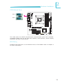
Expansion Slots
2
1
PCI Express x16
PCI Express x4
PCI 1
PCI 2
PCI Express x16 Slot
Install PCI Express x16 graphics card, that comply to the PCI Express specifications, into the PCI Express x16 slot. To install a graphics card into the x16 slot,
align the graphics card above the slot then press it down firmly until it is completely seated in the slot. The retaining clip of the slot will automatically hold the
graphics card in place.
PCI Express x4 Slot
Install PCI Express cards such as network cards or other cards that comply to the
PCI Express specifications into the PCI Express x4 slot.
PCI Slots
The PCI slots support expansion cards that comply with PCI specifications.
50
Hardware Installation
2
Battery
2
1
Battery
The lithium ion battery powers the real-time clock and CMOS memory. It is an
auxiliary source of power when the main power is shut off.
Safety Measures
•
Danger of explosion if battery incorrectly replaced.
•
Replace only with the same or equivalent type recommend by the manufacturer.
•
Dispose of used batteries according to local ordinance.
51
3
BIOS Setup
Chapter 3 - BIOS Setup
Overview
The BIOS is a program that takes care of the basic level of communication between the CPU and peripherals. It contains codes for various advanced features
found in this system board. The BIOS allows you to configure the system and
save the configuration in a battery-backed CMOS so that the data retains even
when the power is off. In general, the information stored in the CMOS RAM of
the EEPROM will stay unchanged unless a configuration change has been made
such as a hard drive replaced or a device added.
It is possible that the CMOS battery will fail causing CMOS data loss. If this happens, you need to install a new CMOS battery and reconfigure the BIOS settings.
Note:
The BIOS is constantly updated to improve the performance of the system board; therefore the BIOS screens in this chapter may not appear
the same as the actual one. These screens are for reference purpose
only.
Default Configuration
Most of the configuration settings are either predefined according to the Load Optimal Defaults settings which are stored in the BIOS or are automatically detected
and configured without requiring any actions. There are a few settings that you
may need to change depending on your system configuration.
Entering the BIOS Setup Utility
The BIOS Setup Utility can only be operated from the keyboard and all commands are keyboard commands. The commands are available at the right side of
each setup screen.
The BIOS Setup Utility does not require an operating system to run. After you
power up the system, the BIOS message appears on the screen and the memory
count begins. After the memory test, the message “Press DEL to run setup” will
appear on the screen. If the message disappears before you respond, restart the
system or press the “Reset” button. You may also restart the system by pressing
the <Ctrl> <Alt> and <Del> keys simultaneously.
52
BIOS Setup
3
Legends
Keys
Function
Right and Left arrows
Moves the highlight left or right to
select a menu.
Up and Down arrows
Moves the highlight up or down
between submenus or fields.
<Esc>
Exits to the BIOS Setup Utility.
+ (plus key)
Scrolls forward through the values
or options of the highlighted field.
- (minus key)
Scrolls backward through the values
or options of the highlighted field.
Tab
Selects a field.
<F1>
Displays General Help.
<F10>
Saves and exits the Setup program.
<Enter>
Press <Enter> to enter the highlighted submenu.
Scroll Bar
When a scroll bar appears to the right of the setup screen, it indicates that there
are more available fields not shown on the screen. Use the up and down arrow
keys to scroll through all the available fields.
Submenu
When ““ appears on the left of a particular field, it indicates that a submenu
which contains additional options are available for that field. To display the submenu, move the highlight to that field and press <Enter>.
53
3
BIOS Setup
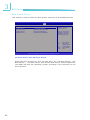
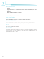
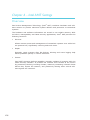
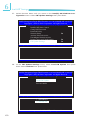
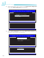
AMI BIOS Setup Utility
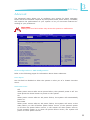
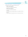
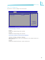
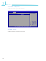
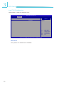
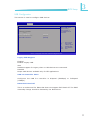
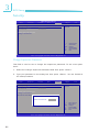
Main
The Main menu is the first screen that you will see when you enter the BIOS
Setup Utility.
Main
Advanced
BIOS SETUP UTILITY
PCIPnP
Boot
Security
System Overview
AMIBIOS
Version
Build Date:
ID
:08.00.15
:01/04/10
:1AAAA000
Processor
Intel(R) Core(TM) i5 CPU
Speed
:3333MHz
Count
:1
Exit
Use [+] or [-] to
configure system Time.
660 @ 3.33GHz
System Memory
Size
760MB
System Time
System Date
Chipset
Use [ENTER], [TAB]
or [SHIFT-TAB] to
select a field.
[09:39:25]
[Mon 01/25/2010]
← →
↑↓ +- Tab F1 F10 ESC Select Screen
Select Item
Change Field
Select Field
General Help
Save and Exit
Exit
v02.67 (C)Copyright 1985-2009, American Megatrends, Inc.
AMI BIOS
Displays the detected BIOS information.
Processor
Displays the detected processor information.
System Memory
Displays the detected system memory information.
System Time
The time format is <hour>, <minute>, <second>. The time is based on the 24hour military-time clock. For example, 1 p.m. is 13:00:00. Hour displays hours
from 00 to 23. Minute displays minutes from 00 to 59. Second displays seconds
from 00 to 59.
System Date
The date format is <day>, <month>, <date>, <year>. Day displays a day, from
Sunday to Saturday. Month displays the month, from January to December. Date
displays the date, from 1 to 31. Year displays the year, from 1980 to 2099.
54
BIOS Setup
3
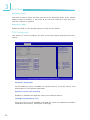
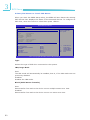
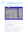
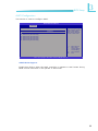
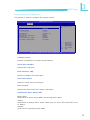
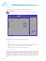
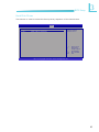
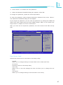
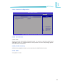
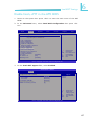
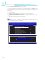
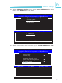
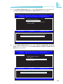
Advanced
The Advanced menu allows you to configure your system for basic operation.
Some entries are defaults required by the system board, while others, if enabled,
will improve the performance of your system or let you set some features according to your preference.
Important:
Setting incorrect field values may cause the system to malfunction.
Main
Advanced
BIOS SETUP UTILITY
PCIPnP
Boot
Security
Chipset
Exit
Configure CPU.
Advanced Settings
WARNING: Setting wrong values in belowsections
may cause system to malfunction.
CPU Configuration
IDE Configuration
Floppy Configuration
Super IO Configuration
Hardware Health Configuration
ACPI Configuration
AHCI Configuration
Intel AMT Configuration
Intel VT-d Configuration
Remote Access Configuration
Trusted Computing
USB Configuration
Case Open
[Disabled]
AC Power Lose
[ON]
Watchdog Timer
[Disabled]
Resume by PME
[Disabled]
← →
↑↓ Enter
F1 F10 ESC Select Screen
Select Item
Go to Sub Screen
General Help
Save and Exit
Exit
v02.67 (C)Copyright 1985-2009, American Megatrends, Inc.
CPU Configuration to USB Configuration
Refer to the following pages for information about these submenus.
Case Open
Set this field to Enabled to allow the system to alert you of a chassis intrusion
event.
AC Power Lose
Off
When power returns after an AC power failure, the system’s power is off. You
must press the Power button to power-on the system.
On
When power returns after an AC power failure, the system will automatically
power-on.
Last State
When power returns after an AC power failure, the system will return to the
state where you left off before power failure occurs. If the system’s power
is off when AC power failure occurs, it will remain off when power returns.
If the system’s power is on when AC power failure occurs, the system will
power-on when power returns.
55
3
BIOS Setup
Watchdog Timer
This field is used to select the time interval of the Watchdog timer. If the system
hangs or fails to function, it will reset at the set time interval so that your system will continue to operate.
Resume by PME
Enable this field to use the PME signal to wake up the system.
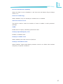
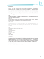
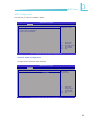
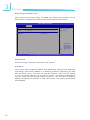
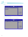
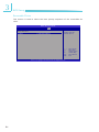
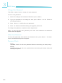
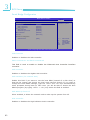
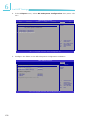
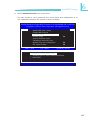
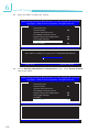
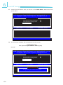
CPU Configuration
This section is used to configure the CPU. It will also display detected CPU information.
BIOS SETUP UTILITY
Manufacturer : Intel
Intel(R) Core(TM) i5 CPU
660 @ 3.33GHz
Frequency
: 3.33GHz
BCLK Speed : 133MHz
Cache L1
: 128 KB
Cache L2
: 512 KB
Cache L3
: 4096 KB
Ratio Status : Unlocked (Min:09; Max:25)
Ratio Actual Value: 25
[Enabled]
[Enabled]
[Enabled]
[Enabled]
[Enabled]
[All]
[Disabled]
[Enabled]
[Enabled]
[Enabled]
For UP platforms,
leave it enabled.
For DP/MP servers,
it may use to tune
performance to the
specific application.
← →
↑↓
Hardware Prefetcher
Adjacent Cache Line Prefetch
Intel(R) Virtualization Tech
Execute-Disable Bit Capability
Intel (R) HT Technology
Active Processor Cores
A20M
Intel(R) SpeedStep(TM) tech
Intel(R) C-STATE tech
Intel(R) TurboMode tech
Advanced
+- F1 F10 ESC Select Screen
Select Item
Change Option
General Help
Save and Exit
Exit
v02.67 (C)Copyright 1985-2009, American Megatrends, Inc.
Hardware Prefetcher
For UP platforms, leave it enabled. For DP/MP servers, it may be used to tune
performance to the specific application.
Adjacent Cache Line Prefetch
Enables or disables the Adjacent Cache Line Prefetch feature.
Intel(R) Virtualization Tech
When this field is set to Enabled, the VMM can utilize the additional hardware
capabilities provided by Vanderpool Technology.
56
BIOS Setup
3
Execute Disable Bit Capability
When this field is set to Disabled, it will force the XD feature flag to always
return to 0.
Intel HT Technology
When disabled, only one thread per enabled core is enabled.
Active Processor Cores
This field is used to enter the number of cores to enable in each processor
package.
A20M
Enable this for legacy operating systems and APs.
Intel(R) SpeedStep(tm) Tech
Enables or disables GV3.
Intel(R) C-STATE Tech
When enabled, CPU idle is set to C2/C3/C4.
Intel(R) TurboMode Tech
When Enabled, Turbo mode allows processor cores to run faster than marked
frequency in specific conditions.
57
3
BIOS Setup
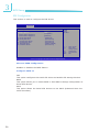
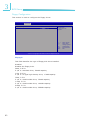
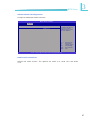
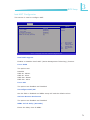
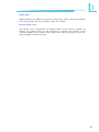
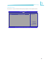
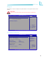
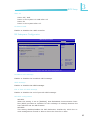
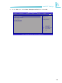
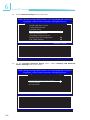
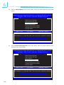
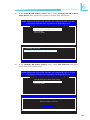
IDE Configuration
This section is used to configure the IDE drives.
BIOS SETUP UTILITY
Advanced
IDE Configuration
Mirrored IDER Configuration
Configure SATA as
SATA#1 IDE Configuration
SATA#2 IDE Configuration
[Enabled]
[IDE]
[Compatible]
[Enhanced]
Primary IDE Master
Primary IDE Slave
Secondary IDE Master
Secondary IDE Slave
Third IDE Master
Fourth IDE Master
:
:
:
:
:
:
IDE
RAID
AHCI
Disabled
[Hard Disk]
[Not Detected]
[Not Detected]
[Not Detected]
[ATAPI CDROM]
[Not Detected]
← →
↑↓ +- F1 F10 ESC Select Screen
Select Item
Change Option
General Help
Save and Exit
Exit
v02.67 (C)Copyright 1985-2009, American Megatrends, Inc.
Mirrored IDER Configuration
Enables or disables the IDER feature.
Configure SATA as
IDE
This option configures the Serial ATA drives as Parallel ATA storage devices.
RAID
This option allows you to create RAID or Intel Matrix Storage configuration on
Serial ATA devices.
AHCI
This option allows the Serial ATA devices to use AHCI (Advanced Host Controller Interface).
58
BIOS Setup
3
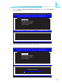
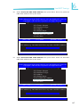
SATA#1 IDE Configuration / SATA#2 IDE Configuration
These fields are used to configure the IDE device mode.
SATA#1 IDE Configuration
The options are Compatible and Enhanced.
SATA#2 IDE Configuration
The options are Disabled and Enhanced.
Compatible
Legacy IDE channels will appear allowing you to configure the devices.
Enhanced
”Configure SATA as” will appear allowing you to configure the devices.
59
3
BIOS Setup
Primary IDE Master to Fourth IDE Master
When you enter the BIOS Setup Utility, the BIOS will auto detect the existing
IDE devices then displays the status of the detected devices. To configure an
IDE drive, move the cursor to a field then press <Enter>.
BIOS SETUP UTILITY
Advanced
Select the type
of device connected
to the system.
Primary IDE Master
Device
Vendor
Size
LBA Mode
Block Mode
PIO Mode
Async. DMA
Ultra DMA
S.M.A.R.T
:Hard Disk
:ST3120023AS
:120.0GB
:Supported
:16Sectors
:4
:Multiword DMA-2
:Ultra DMA-6
:Supported
Type
LBA/Large Mode
Block (Multi-Sector Transfer)
PIO Mode
DMA Mode
S.M.A.R.T.
32Bit Data Transfer
[Auto]
[Auto]
[Auto]
[Auto]
[Auto]
[Auto]
[Enabled]
← →
↑↓ +- F1 F10 ESC Select Screen
Select Item
Change Option
General Help
Save and Exit
Exit
v02.67 (C)Copyright 1985-2009, American Megatrends, Inc.
Type
Selects the type of IDE drive connected to the system.
LBA/Large Mode
Auto
The LBA mode will automatically be enabled, that is, if the LBA mode was not
previously disabled.
Disabled
Disables the LBA mode.
Block (Multi-Sector Transfer)
Auto
Data transfer from and to the device occurs multiple sectors at a time.
Disabled
Data transfer from and to the device occurs one sector at a time.
60
BIOS Setup
3
PIO Mode
Selects the data transfer mode. PIO means Programmed Input/Output.
Rather than have the BIOS issue a series of commands to effect a transfer
to or from the disk drive, PIO allows the BIOS to tell the controller what it
wants and then let the controller and the CPU perform the complete task by
themselves. Your system supports five modes, 0 to 4, which primarily differ
in timing. When Auto is selected, the BIOS will select the best available mode
after checking your drive.
Auto The default is Auto. The BIOS will automatically set the system according to
your hard disk drive’s timing.
Mode 0-4
You can select a mode that matches your hard disk drive’s timing. Caution:
Do not use the wrong setting or you will have drive errors.
DMA Mode
This field allows you to set the Ultra DMA in use. When Auto is selected, the
BIOS will select the best available option after checking your hard drive or
CD-ROM.
Auto
Automatically detects the DMA mode.
SWDMAn
SingleWord DMAn.
MWDMAn
MultiWord DMAn.
UDMAn
Ultra DMAn.
S.M.A.R.T.
The system board supports SMART (Self-Monitoring, Analysis and Reporting
Technology) hard drives. SMART is a reliability prediction technology for ATA/
IDE and SCSI drives. The drive will provide sufficient notice to the system or
user to backup data prior to the drive’s failure. SMART is supported in ATA/33
or later hard drives. The options are Auto (default), Enabled and Disabled.
32Bit Data Transfer
Enables or disables 32-bit data transfer.
61
3
BIOS Setup
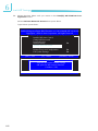
Floppy Configuration
This section is used to configure the floppy drives.
BIOS SETUP UTILITY
Advanced
Floppy Configuration
[1.44MB 3 1/2’’]
Floppy A
Select the type of
floppy drive
connected to the
system.
← →
↑↓ +- F1 F10 ESC v02.67 (C)Copyright 1985-2009, American Megatrends, Inc.
Floppy A
This field identifies the type of floppy disk drive installed.
Disabled Disables the floppy drive
360K, 5.25 in.
5-1/4 in. standard drive; 360KB capacity
1.2M, 5.25 in.
5-1/4 in. AT-type high-density drive; 1.2MB capacity
720K, 3.5 in.
3-1/2 in. double-sided drive; 720KB capacity
1.44M, 3.5 in.
3-1/2 in. double-sided drive; 1.44MB capacity
2.88M, 3.5 in.
3-1/2 in. double-sided drive; 2.88MB capacity
62
Select Screen
Select Item
Change Option
General Help
Save and Exit
Exit
BIOS Setup
3
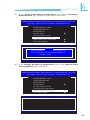
Super IO Configuration
This section is used to configure the I/O functions.
BIOS SETUP UTILITY
Advanced
Configure F71879F Super IO Chipset
Onboard Floppy Controller
Serial Port1 Address
Serial Port2 Address
[Enabled]
[3F8/IRQ4]
[2F8/IRQ3]
Allows BIOS to Enable or Disable Floppy
Controller.
← →
↑↓ +- F1 F10 ESC Select Screen
Select Item
Change Option
General Help
Save and Exit
Exit
v02.67 (C)Copyright 1985-2009, American Megatrends, Inc.
Onboard Floppy Controller
Enabled Enables the onboard floppy disk controller.
Disabled Disables the onboard floppy disk controller.
Serial Port1 Address and Serial Port2 Address
3F8/IRQ4, 2F8/IRQ3, 3E8/IRQ4, 2E8/IRQ3 Allows you to manually select an I/O address for the onboard serial port 1
and serial port 2.
Disabled
Disables the onboard serial port 1 and/or serial port 2.
63
3
BIOS Setup
Hardware Health Configuration
This section is used to configure the hardware monitor function.
BIOS SETUP UTILITY
Hardware Health Configuration
H/W Health Function
CPU Temperature
System Temperature
Advanced
[Enabled]
Min=0
Max=100
Please input Dec number:
:38oC
:29oC
:1335 RPM
:N/A
Vcore
5V
+12V
V_DIMM
5VSB
3.3V
VBAT
CPU FAN Mode Setting-Smart FAN
Highest CPU Temperature Limit
2nd CPU Temperature Limit
3rd CPU Temperature Limit
Lowest CPU Temperature Limit
CPU Fan Highest Setting
CPU Fan Second Setting
CPU Fan Third Setting
CPU Fan Fourth Setting
CPU Fan Lowest Setting
:1.144 V
:4.743 V
:12.232V
:1.536 V
:5.056V
:3.248V
:3.328V
[Auto Mode]
[080]
[065]
[050]
[035]
[100]
[080]
[070]
[060]
[050]
← →
↑↓
CPUFAN Speed
SystemFAN Speed
Lowest Speed Value
Enter
F1 F10 ESC Select Screen
Select Item
Update
General Help
Save and Exit
Exit
v02.67 (C)Copyright 1985-2009, American Megatrends, Inc.
H/W Health Function
Enables or disables the hardware monitoring function.
CPU Temperature to VBAT
These fields will show the temperature, fan speed and output voltage of the
monitored devices or components.
CPU Fan Mode Setting-Smart Fan
Enable this function to configure the CPU temperature’s limit and the CPU
fan’s settings.
Highest CPU Temperature Limit to Lowest CPU Temperature Limit
Sets the CPU’s highest, 2nd, 3rd and lowest temperature limit.
CPU Fan Highest Setting to CPU Fan Lowest Setting
Sets the CPU fan’s highest, 2nd, 3rd, 4th and lowest fan speed limit.
64
BIOS Setup
3
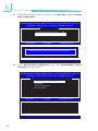
ACPI Configuration
This section is used to configure ACPI.
BIOS SETUP UTILITY
Advanced
General ACPI
configuration settings
ACPI Settings
General ACPI Configuration
Advanced ACPI Configuration
Chipset ACPI Configuration
← →
↑↓ Enter
F1 F10 ESC Select Screen
Select Item
Go to Sub Screen
General Help
Save and Exit
Exit
v02.67 (C)Copyright 1985-2009, American Megatrends, Inc.
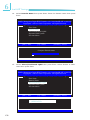
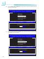
General ACPI Configuration
Configures the general ACPI settings.
BIOS SETUP UTILITY
Advanced
General ACPI Configuration
Suspend mode
[S1 (POS)]
Select the ACPI
state used for
System Suspend.
← →
↑↓ +- F1 F10 ESC Select Screen
Select Item
Change Option
General Help
Save and Exit
Exit
v02.67 (C)Copyright 1985-2009, American Megatrends, Inc.
65
3
BIOS Setup
Suspend Mode
This field is used to select the type of Suspend mode.
S1(POS)
Enables the Power On Suspend function.
S3(STR)
Enables the Suspend to RAM function.
66
BIOS Setup
3
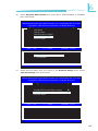
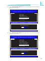
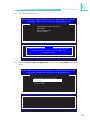
Advanced ACPI Configuration
Configures additional ACPI functions.
BIOS SETUP UTILITY
Advanced
Advanced ACPI Configuration
ACPI Version Features
[ACPI v1.0]
Enable RSDP pointers
to 64-bit Fixed System
Description Tables.
Different ACPI version
has some addition.
← →
↑↓ +- F1 F10 ESC Select Screen
Select Item
Change Option
General Help
Save and Exit
Exit
v02.67 (C)Copyright 1985-2009, American Megatrends, Inc.
ACPI Version Features
Selects the ACPI version. The options are ACPI v1.0, ACPI v2.0 and ACPI
v3.0.
67
3
BIOS Setup
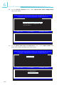
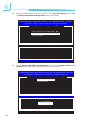
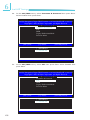
Chipset ACPI Configuration
Configures relevant chipset ACPI functions.
BIOS SETUP UTILITY
Advanced
South Bridge ACPI Configuration
APIC ACPI SCI IRQ
[Disabled]
Enable/Disable APIC
ACPI SCI IRQ.
← →
↑↓ +- F1 F10 ESC v02.67 (C)Copyright 1985-2009, American Megatrends, Inc.
APIC ACPI SCI IRQ
Enables or disables the APIC ACPI SCI IRQ.
68
Select Screen
Select Item
Change Option
General Help
Save and Exit
Exit
BIOS Setup
3
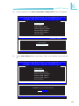
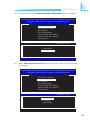
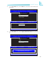
AHCI Configuration
This section is used to configure AHCI.
BIOS SETUP UTILITY
Advanced
AHCI Settings
[Enabled]
AHCI BIOS Support
AHCI
AHCI
AHCI
AHCI
AHCI
AHCI
Port0
Port1
Port2
Port3
Port4
Port5
[Not
[Not
[Not
[Not
[Not
[Not
Detected]
Detected]
Detected]
Detected]
Detected]
Detected]
Enables for supporting
AHCI controller operates
in AHCI mode during
BIOS control otherwise
operates in IDE mode.
← →
↑↓ +- F1 F10 ESC Select Screen
Select Item
Change Option
General Help
Save and Exit
Exit
v02.67 (C)Copyright 1985-2009, American Megatrends, Inc.
AHCI BIOS Support
Enable this field to allow the AHCI controller to operate in AHCI mode during
BIOS control otherwise it will operate in IDE mode.
69
3
BIOS Setup
AHCI Port0 to AHCI Port5
When entering the setup utility, the BIOS auto detects the presence of any
IDE devices. It displays the status of the auto detected IDE devices.
BIOS SETUP UTILITY
Advanced
Select the type
of device connected
to the system.
AHCI Port0
Device
SATA Port0
S.M.A.R.T.
:Not Detected
[Auto]
[Enabled]
← →
↑↓ +- F1 F10 ESC Select Screen
Select Item
Change Option
General Help
Save and Exit
Exit
v02.67 (C)Copyright 1985-2009, American Megatrends, Inc.
SATA Port0
Selects the type of device connected to the system.
S.M.A.R.T.
The system board supports SMART (Self-Monitoring, Analysis and Reporting
Technology) hard drives. SMART is a reliability prediction technology for ATA/
IDE and SCSI drives. The drive will provide sufficient notice to the system
or user to backup data prior to the drive’s failure. The default is Disabled. If
you are using hard drives that support S.M.A.R.T., set this field to Enabled.
SMART is supported in ATA/33 or later hard drives. The options are Enabled
and Disabled.
70
BIOS Setup
3
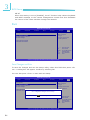
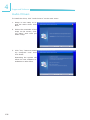
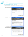
Intel AMT Configuration
This section is used to configure AMT.
BIOS SETUP UTILITY
Advanced
Configure Intel AMT Parameters
Intel AMT Support
Force IDER
Force SOL
Unconfigure AMT/ME
Activate Remote Assistance
MEBx Ctrl+P Delay (Seconds)
Options
[Enabled]
[Disabled]
[Disabled]
[Disabled]
[Disabled]
[0]
Disabled
Enabled
← →
↑↓ +- F1 F10 ESC Select Screen
Select Item
Change Option
General Help
Save and Exit
Exit
v02.67 (C)Copyright 1985-2009, American Megatrends, Inc.
Intel AMT Support
Enables or disables Intel’s AMT (Active Management Technology) function.
Force IDER
The options are:
Disabled
IDER Pri. Master
IDER Pri. Slave
IDER Sec. Master
IDER Sec. Slave
Force SOL
The options are Enabled and Disabled.
Unconfigure AMT/ME
Set this field to Enabled and MEBx setup will load the default values.
Activate Remote Assistance
The options are Enabled and Disabled.
MEBx Ctrl+P Delay (Seconds)
Enters the delay time of MEBx.
71
3
BIOS Setup
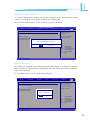
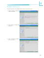
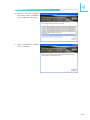
Intel VT-d Configuration
This section is used to configure VT-d.
BIOS SETUP UTILITY
Advanced
Options
Intel VT-d
[Disabled]
Disabled
Enabled
← →
↑↓ +- F1 F10 ESC v02.67 (C)Copyright 1985-2009, American Megatrends, Inc.
Intel VT-d
The options are Enabled and Disabled.
72
Select Screen
Select Item
Change Option
General Help
Save and Exit
Exit
BIOS Setup
3
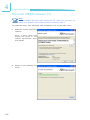
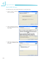
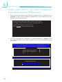
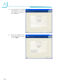
Remote Access Configuration
This section is used to configure the remote access.
BIOS SETUP UTILITY
Advanced
Configure Remote Access Type and Parameters
Remote Access
[Enabled]
Serial Port Number
Base Address, IRQ
Serial Port Mode
Flow Control
Redirection After BIOS POST
Terminal Type
VT-UTF8 Combo Key Support
Sredir Memory Display Delay
[COM3]
[D000h, 5]
[115200 8, n, l]
[None]
[Always]
[ANSI]
[Enabled]
[No Delay]
Select Remote Access
type.
← →
↑↓ +- F1 F10 ESC Select Screen
Select Item
Change Option
General Help
Save and Exit
Exit
v02.67 (C)Copyright 1985-2009, American Megatrends, Inc.
Remote Access
Enables or disables the remote access feature.
Serial Port Number
Selects the serial port.
Base Address, IRQ
Selects an IRQ for the serial port.
Serial Port Mode
Selects a mode for the serial port.
Flow Control
Selects the flow control for console redirection.
Redirection After BIOS POST
Boot Loader
Redirection is active during POST and during Boot Loader.
Always
Redirection is always active. Some OSes may not work when this field is set
to Always.
Disable
Turns off the redirection after POST.
73
3
BIOS Setup
Terminal Type
Selects the target terminal type.
VT-UTF8 Combo Key Support
Enables or disables VT-UTF8 combination key support for ANSI/VT100 terminals.
Sredir Memory Display Delay
Selects the delay time (in seconds) before displaying the memory information.
74
BIOS Setup
3
Trusted Computing (optional)
This section configures settings relevant to Trusted Computing innovations.
BIOS SETUP UTILITY
Advanced
Trusted Computing
[No]
TCG/TPM Support
Enable/Disable TPM
TCG (TPM 1.1/1.2)
support in BIOS
← →
↑↓ +- F1 F10 ESC Select Screen
Select Item
Change Option
General Help
Save and Exit
Exit
v02.67 (C)Copyright 1985-2009, American Megatrends, Inc.
TCG/TPM Support
Enables or disables TPM TCG. The options are Yes and No.
If you selected Yes, additional fields will appear.
BIOS SETUP UTILITY
Advanced
Trusted Computing
TCG/TPM Support
[Yes]
Execute TPM Command
Clearing the TPM
TPM Enable/Disable Status
TPM Owner Status
[Don’t change]
[Press Enter]
[Disabled]
[UnOwned]
Enable/Disable TPM
TCG (TPM 1.1/1.2)
support in BIOS
← →
↑↓ +- F1 F10 ESC Select Screen
Select Item
Change Option
General Help
Save and Exit
Exit
v02.67 (C)Copyright 1985-2009, American Megatrends, Inc.
75
3
BIOS Setup
Execute TPM Command
Enables (activates) or disables (deactivates) command to TPM.
Clearing the TPM
This field allows you to clear the user information saved in the TPM security
chip. When you press <Enter>, a warning message will appear to ask if you
want to clear the user information in the security chip. Use the left / right arrow key to select between [OK] and [Cancel], then press <Enter> to confirm
your choice.
TPM Enable/Disable Status
Enables or disables the TPM status.
TPM Owner Status
Enables or disables the TPM owner’s status.
76
BIOS Setup
3
USB Configuration
This section is used to configure USB devices.
BIOS SETUP UTILITY
Advanced
USB Configuration
Enables support for
legacy USB. AUTO
option disables
legacy support if
no USB devices are
connected.
Module Version - 2.24.5-13.4
USB Devices Enabled :
2 Hubs
Legacy USB Support
USB 2.0 Controller Mode
BIOS EHCI Hand-Off
[Enabled]
[HiSpeed]
[Enabled]
← →
↑↓ +- F1 F10 ESC Select Screen
Select Item
Change Option
General Help
Save and Exit
Exit
v02.67 (C)Copyright 1985-2009, American Megatrends, Inc.
Legacy USB Support
Enabled
Enables Legacy USB.
Auto
Disables support for Legacy when no USB devices are connected.
Disabled
Keeps USB devices available only for EFI applications.
USB 2.0 Controller Mode
Configures the USB 2.0 controller in HiSpeed (480Mbps) or FullSpeed
(12Mbps).
BIOS EHCI Hand-Off
This is a workaround for OSes that does not support EHCI hand-off. The EHCI
ownership change should be claimed by the EHCI driver.
77
3
BIOS Setup
PCIPnP
The PCIPnP menu is used to configure PCI Plug and Play devices.
Important:
Setting incorrect field values may cause the system to malfunction.
Main
Advanced
BIOS SETUP UTILITY
PCIPnP
Boot
Security
Chipset
Exit
Clear NVRAM during
System Boot.
Advanced PCI/PnP Settings
WARNING: Setting wrong values in belowsections
may cause system to malfunction.
Clear NVRAM
Plug & Play O/S
PCI Latency Timer
[No]
[No]
[64]
IRQ3
IRQ4
IRQ5
IRQ7
IRQ9
IRQ10
IRQ11
IRQ14
IRQ15
[Available]
[Available]
[Available]
[Available]
[Available]
[Available]
[Available]
[Available]
[Available]
← →
↑↓ +-
F1 F10 ESC Select Screen
Select Item
Change Option
General Help
Save and Exit
Exit
v02.67 (C)Copyright 1985-2009, American Megatrends, Inc.
Clear NVRAM
This field allows clearing the NVRAM during system boot.
Plug & Play O/S
Yes
The operating system configures Plug and Play (PnP) devices that are not required to boot in a Plug and Play supported operating system.
No
The BIOS configures all the devices in the system.
PCI Latency Timer
This feature is used to select the length of time each PCI device will control the
bus before another takes over. The larger the value, the longer the PCI device
can retain control of the bus. Since each access to the bus comes with an initial
delay before any transaction can be made, low values for the PCI Latency Timer
will reduce the effectiveness of the PCI bandwidth while higher values will improve it.
78
BIOS Setup
3
IRQ3 to IRQ15
Available
The specified IRQ is available for PCI/PnP devices.
Reserved
The specified IRQ is reserved for Legacy ISA devices.
79
3
BIOS Setup
Boot
Main
Advanced
BIOS SETUP UTILITY
PCIPnP
Boot
Security
Boot Settings
Boot
Chipset
Exit
Configure settings
during system boot.
Settings Configuration
Boot Device Priority
Hard Disk Drives
Removable Drives
CD/DVD Drives
← →
↑↓ Enter F1 F10 ESC Select Screen
Select Item
Go to Sub Screen
General Help
Save and Exit
Exit
v02.67 (C)Copyright 1985-2009, American Megatrends, Inc.
Boot Settings Configuration
This section is used to configure settings during system boot.
BIOS SETUP UTILITY
Boot
Boot Settings Configuration
Quiet Boot
Bootup Num-Lock
[Disabled]
[On]
Allows BIOS to skip
certain tests while
booting. This will
decrease the time
needed to boot the
system.
← →
↑↓ +- F1 F10 ESC v02.67 (C)Copyright 1985-2009, American Megatrends, Inc.
80
Select Screen
Select Item
Change Option
General Help
Save and Exit
Exit
BIOS Setup
3
Quick Boot
When Enabled, the BIOS will shorten or skip some check items during POST.
This will decrease the time needed to boot the system.
Bootup Num-Lock
This allows you to determine the default state of the numeric keypad. By
default, the system boots up with NumLock on wherein the function of the
numeric keypad is the number keys. When set to Off, the function of the numeric keypad is the arrow keys.
81
3
BIOS Setup
Boot Device Priority
This section is used to select the boot priority sequence of all available devices.
BIOS SETUP UTILITY
Boot
Boot Device Priority
1st Boot Device
2nd Boot Device 3rd Boot Device
4th Boot Device
[1st FLOPPY DRIVE]
[HDD:PM-ST3120023AS]
[Network: Realtek PX]
[CD/DVD:3M-POINEER]
Specifies the boot
sequence from the
available devices.
A device enclosed in
parenthesis has been
disabled in the corresponding type menu.
← →
↑↓ +- F1 F10 ESC Select Screen
Select Item
Change Option
General Help
Save and Exit
Exit
v02.67 (C)Copyright 1985-2009, American Megatrends, Inc.
1st Boot Device and 4th Boot Device
Select the drive to boot 1st, 2nd, 3rd and 4th in the “1st Boot Device”, “2nd
Boot Device” , “3rd Boot Device” and “Fourth Boot Device” fields respectively.
The BIOS will boot the operating system according to the sequence of the
drive selected.
82
BIOS Setup
3
Hard Disk Drives
This section is used to select the boot priority sequence of the hard drives.
BIOS SETUP UTILITY
Boot
Hard Disk Drives
1st Drive [HDD: PM-ST3120023AS]
Specifies the boot
sequence from the
available devices.
← →
↑↓ +- F1 F10 ESC Select Screen
Select Item
Change Option
General Help
Save and Exit
Exit
v02.67 (C)Copyright 1985-2009, American Megatrends, Inc.
83
3
BIOS Setup
Removable Drives
This section is used to select the boot priority sequence of the removable devices.
BIOS SETUP UTILITY
Boot
Removable Drives
1st Drive
[1st FLOPPY DRIVE]
Specifies the boot
sequence from the
available devices.
← →
↑↓ +- F1 F10 ESC v02.67 (C)Copyright 1985-2009, American Megatrends, Inc.
84
Select Screen
Select Item
Change Option
General Help
Save and Exit
Exit
BIOS Setup
3
CD/DVD Drives
This section is used to select the boot priority sequence of the optical devices.
BIOS SETUP UTILITY
Boot
CD/DVD Drives
1st Drive
[CD/DVD:3M-POINEER]
Specifies the boot
sequence from the
available devices.
← →
↑↓ +- F1 F10 ESC Select Screen
Select Item
Change Option
General Help
Save and Exit
Exit
v02.67 (C)Copyright 1985-2009, American Megatrends, Inc.
85
3
BIOS Setup
Security
Main
BIOS SETUP UTILITY
PCIPnP
Boot
Security
Advanced
Security Settings
Supervisor Password
User Password
: Not Installed
: Not Installed
Chipset
Exit
Install or Change the
password.
Change Supervisor Password
Change User Password
← →
↑↓ Enter F1 F10 ESC Select Screen
Select Item
Change
General Help
Save and Exit
Exit
v02.67 (C)Copyright 1985-2009, American Megatrends, Inc.
Change Supervisor Password
This field is used to set or change the supervisor password. To set a new password:
1. Select the Change Supervisor Password field then press <Enter>.
2. Type your password in the dialog box then press <Enter>. You are limited to
six letters/numbers.
Main
BIOS SETUP UTILITY
PCIPnP
Boot
Security
Advanced
Security Settings
Supervisor Password
User Password
: Not Installed
: Not Installed
Chipset
Exit
Install or Change the
password.
Change Supervisor Password
Change User Password
Boot Sector Virus Protection [Disabled]
Enter New Password
← →
↑↓ Enter F1 F10 ESC v02.61 (C)Copyright 1985-2006, American Megatrends, Inc.
86
Select Screen
Select Item
Change
General Help
Save and Exit
Exit
BIOS Setup
3
3. Press <Enter> to confirm the new password.
4. When the Password Installed dialog box appears, select OK.
To change the password, repeat the same steps above.
To clear the password, select Change Supervisor Password then press <Enter>.
The Password Uninstalled dialog box will appear.
If you forgot the password, you can clear the password by erasing the CMOS RTC
(Real Time Clock) RAM using the Clear CMOS jumper. Refer to the Jumper Settings section in chapter 2 for more information.
After you have set the supervisor password, the User Access Level field will appear.
Main
Advanced
BIOS SETUP UTILITY
PCIPnP
Boot
Security
Security Settings
Supervisor Password
User Password
: Installed
: Not Installed
Change Supervisor Password
User Access Level
Change User Password
Password Check
[Full Access]
[Setup]
Chipset
Exit
Limited: only limited
fields to be changed.
No Access: prevent user
access Setup Utility.
View Only: allow access but the fields can
not be changed.
Full: allow change
except Supervisor
password.
← →
↑↓ +- F1 F10 ESC Select Screen
Select Item
Change Option
General Help
Save and Exit
Exit
v02.61 (C)Copyright 1985-2006, American Megatrends, Inc.
User Access Level
Selects the access level to the fields in the Setup utility.
Limited
Allows you to change settings to some fields such as Date and Time.
No Access
Prevents access to the Setup utility.
View Only
Allows you to view the settings but does not allow you to change the settings.
Full Access
Allows you to change settings to all the fields in the utility.
87
3
BIOS Setup
Change User Password
This field is used to set or change the user password.
To set a new password:
1. Select the Change User Password field then press <Enter>.
2. Type your password in the dialog box then press <Enter>. You are limited to
six letters/numbers.
3. Press <Enter> to confirm the new password.
4. When the Password Installed dialog box appears, select OK.
To change the password, repeat the same steps above.
After you have set the user password, the Clear User Password and Password
Check fields will appear.
Clear User Password
To clear the password, select Clear User Password then press <Enter>. The Password Uninstalled dialog box will appear.
Password Check
Setup The BIOS checks for the user password whenever accessing the Setup utility.
Always The BIOS checks for the user password when accessing the Setup utility and
booting the system.
88
BIOS Setup
3
Chipset
This section is used to configure the system based on the specific features of the
chipset.
Important:
Setting incorrect field values may cause the system to malfunction.
Main
Advanced
BIOS SETUP UTILITY
PCIPnP
Boot
Security
Advanced Chipset Settings
WARNING: Setting wrong values in belowsections may cause system to malfunction.
North Bridge Configuration
South Bridge Configuration
ME Subsystem Configuration
Chipset
Exit
Configure North Bridge
features.
← →
↑↓ Enter
F1 F10 ESC Select Screen
Select Item
Go to Sub Screen
General Help
Save and Exit
Exit
v02.67 (C)Copyright 1985-2009, American Megatrends, Inc.
North Bridge Configuration
BIOS SETUP UTILITY
Chipset
North Bridge Chipset Configuration
IMC Type:
*Dale Family IMC
Memory Remap Feature [Enabled]
PCI MMIO Allocation: 4GB to 3072MB
DRAM Frequency [Auto]
Initiate Graphic Adapter [PEG/PCI]
IGD Graphics Mode Select [Enabled, 128MB]
IGD GIT Graphics Memory Size [No VT mode, 2MB]
NB PCIE Configuration
PEG Port [Auto]
PEG Force GEN1 [Disabled]
Video
Function Configuration
ENABLE: Allow
remapping of
overlapped PCI
memory above the total
physical memory.
DISABLE: Do not
allow remapping of
memory.
← →
↑↓ +- F1 F10 ESC Select Screen
Select Item
Change Option
General Help
Save and Exit
Exit
v02.67 (C)Copyright 1985-2009, American Megatrends, Inc.
89
3
BIOS Setup
Memory Remap Feature
Enabled
Allows remapping of overlapped PCI memory above the total physical memory.
Disabled
Does not allow remapping of memory.
DRAM Frequency
Selects the frequency of the DRAM.
Initiate Graphic Adapter
Selects the graphics controller to use as the primary boot device.
IGD Graphics Mode Select
Selects the amount of system memory used by the internal graphics device.
PEG Port
The options are Auto and Disabled.
PEG Force GEN1
Some PCIE graphics devices does not comply to the PCIE specification and may
incorrectly report their Gen capability or link width. Select Enabled to force the
graphics device in Gen 1 mode.
90
BIOS Setup
3
Video Function Configuration
BIOS SETUP UTILITY
Chipset
Video Function Configuration
DVMT Mode Select [DVMT Mode]
DVMT/FIXED Memory [256MB]
PAVP Mode [Lite]
Options
DVMT Mode
← →
↑↓ +- F1 F10 ESC Select Screen
Select Item
Change Option
General Help
Save and Exit
Exit
v02.67 (C)Copyright 1985-2009, American Megatrends, Inc.
DVMT Mode Select
DVMT Mode
Memory that is dynamically allocated based on memory requests made by an
application and are released back to the system once the requesting application has been terminated.
DVMT/FIXED Memory
Selects the graphics memory size used by the DVMT/Fixed mode.
PAVP Mode
The option is Lite.
91
3
BIOS Setup
South Bridge Configuration
BIOS SETUP UTILITY
Chipset
South Bridge Chipset Configuration
USB Function
EHCI Controller#1
EHCI Controller#2
GbE Controller
GbE LAN Boot
GbE Wake Up From S5
HDA Controller
[Enabled]
[Enabled]
[Enabled]
[Enabled]
[Disabled]
[Disabled]
[Enabled]
Enable/Disable USB
controller in system.
After G3 [Power On]
PCIE Ports Configuration
Onboard LAN2 [Auto]
← →
↑↓ +- F1 F10 ESC Select Screen
Select Item
Change Option
General Help
Save and Exit
Exit
v02.67 (C)Copyright 1985-2009, American Megatrends, Inc.
USB Functions
Enables or disables the USB controller.
EHCI Controller#1 and EHCI Controller#2
This field is used to enable or disable the Enhanced Host Controller Interface
controller.
GbE Controller
Enables or disables the Gigabit LAN controller.
GbE LAN Boot (for onboard Intel)
Enable this field if you want to use the boot ROM (instead of a disk drive) to
boot-up the system and access the local area network directly. If you want to
change the boot ROM’s settings, type the <Ctrl> and <S> keys simultaneously
when prompted during boot-up. Take note: you will be able to access the boot
ROM’s program (by typing <Ctrl> + <S>) only when this field is enabled.
GbE Wake Up From S5
When enabled, it allows the network LAN to wake up the system from S5.
HDA Controller
Enables or disables the High Definition Audio controller.
92
BIOS Setup
3
After G3
Power Off / WOL
Power-on the system via WOL after G3.
Power On
Power-on the system after G3.
On Board LAN2
Enables or disables the LAN2 controller.
ME Subsystem Configuration
BIOS SETUP UTILITY
Chipset
ME Subsystem Configuration
BootBlock HECI Message [Enabled]
HECI Message [Enabled]
End Of Post S5 HECI Message [Enabled]
Options
Disabled
Enabled
ME HECI Configuration
ME-HECI [Enabled]
ME-IDER [Enabled]
ME-KT [Enabled]
Management Engine Version: 6.0.3.1195
← →
↑↓ +- F1 F10 ESC Select Screen
Select Item
Change Option
General Help
Save and Exit
Exit
v02.67 (C)Copyright 1985-2009, American Megatrends, Inc.
BootBlock HECI Message
Enables or disables the bootblock HECI message.
HECI Message
Enables or disables the HECI message.
End of Post S5 HECI Message
Enables or disables the end of post S5 HECI message.
ME HECI Configuration
ME-HECI
When this setting is set to [Enabled], Host Embedded Communication Interface (HECI) provides an interface for the exchange of message between the
host software and the ME firmware.
ME-IDER
This setting disables/enables the IDE Redirection interface by which the remote management console is able to direct the client PC to boot.
93
3
BIOS Setup
ME-KT
When this setting is set to [Enabled], the KT function help redirect keyboard
and POST message to the remote management console and thus facilitates
the control of the client machine through the network.
Exit
Main
Advanced
BIOS SETUP UTILITY
PCIPnP
Boot
Security
Chipset
Exit
Exit system setup
after saving the
changes.
Exit Options
Save Changes and Exit
Discard Changes and Exit
Discard Changes
F10 key can be used
for this operation.
Load Optimal Defaults
Load Failsafe Defaults
← →
↑↓ Enter
F1 F10 ESC Select Screen
Select Item
Go to Sub Screen
General Help
Save and Exit
Exit
v02.67 (C)Copyright 1985-2009, American Megatrends, Inc.
Save Changes and Exit
To save the changes and exit the Setup utility, select this field then press <Enter>. A dialog box will appear. Confirm by selecting OK.
You can also press <F10> to save and exit Setup.
Main
Advanced
BIOS SETUP UTILITY
PCIPnP
Boot
Security
Save Changes and Exit
Discard Changes and Exit
Discard Changes
Load Optimal Defaults
Load Failsafe Defaults
Chipset
F10 key can be used
for this operation.
Save configuration changes and exit setup?
[Ok]
[Cancel]
← →
↑↓ Enter
F1 F10 ESC v02.61 (C)Copyright 1985-2006, American Megatrends, Inc.
94
Exit
Exit system setup
after saving the
changes.
Exit Options
Select Screen
Select Item
Go to Sub Screen
General Help
Save and Exit
Exit
BIOS Setup
3
Discard Changes and Exit
To exit the Setup utility without saving the changes, select this field then press
<Enter>. A dialog box will appear. Confirm by selecting OK.
You can also press <ESC> to exit without saving the changes.
Main
Advanced
BIOS SETUP UTILITY
PCIPnP
Boot
Security
Save Changes and Exit
Discard Changes and Exit
Discard Changes
Load Optimal Defaults
Load Failsafe Defaults
Chipset
Exit
Exit system setup
without saving any
changes.
Exit Options
ESC key can be used
for this operation.
Discard changes and exit setup?
[Ok]
[Cancel]
← →
↑↓ Enter
F1 F10 ESC Select Screen
Select Item
Go to Sub Screen
General Help
Save and Exit
Exit
v02.61 (C)Copyright 1985-2006, American Megatrends, Inc.
Discard Changes
To discard the changes, select this field then press <Enter>. A dialog box will appear. Confirm by selecting OK to discard all changes made and restore the previously saved settings.
You can also press <F7> to discard the changes.
Main
Advanced
BIOS SETUP UTILITY
PCIPnP
Boot
Security
Save Changes and Exit
Discard Changes and Exit
Discard Changes
Load Optimal Defaults
Load Failsafe Defaults
Chipset
Exit
Discards changes
done so far to any of
the setup questions.
Exit Options
F7 key can be used
for this operation.
Discard Changes?
[Ok]
[Cancel]
← →
↑↓ Enter
F1 F10 ESC Select Screen
Select Item
Go to Sub Screen
General Help
Save and Exit
Exit
v02.61 (C)Copyright 1985-2006, American Megatrends, Inc.
95
3
BIOS Setup
Load Optimal Defaults
To load optimal default values from the BIOS ROM, select this field then press
<Enter>. A dialog box will appear. Confirm by selecting OK.
You can also press <F9> to load optimal default values.
Main
Advanced
BIOS SETUP UTILITY
PCIPnP
Boot
Security
Save Changes and Exit
Discard Changes and Exit
Discard Changes
Load Optimal Defaults
Load Failsafe Defaults
Chipset
Exit
Load Optimal Default
values for all the
setup questions.
Exit Options
F9 key can be used
for this operation.
Load Optimal Defaults?
[Ok]
[Cancel]
← →
↑↓ Enter
F1 F10 ESC Select Screen
Select Item
Go to Sub Screen
General Help
Save and Exit
Exit
v02.61 (C)Copyright 1985-2006, American Megatrends, Inc.
Load Failsafe Defaults
To load the fail-safe default values from the BIOS ROM, select this field then
press <Enter>. A dialog box will appear. Confirm by selecting OK.
You can also press <F8> to load the fail-safe default values.
Main
Advanced
BIOS SETUP UTILITY
PCIPnP
Boot
Security
Save Changes and Exit
Discard Changes and Exit
Discard Changes
Load Optimal Defaults
Load Failsafe Defaults
Chipset
F8 key can be used
for this operation.
Load Failsafe Defaults?
[Ok]
[Cancel]
← →
↑↓ Enter
F1 F10 ESC v02.61 (C)Copyright 1985-2006, American Megatrends, Inc.
96
Exit
Load Failsafe Default
values for all the
setup questions.
Exit Options
Select Screen
Select Item
Go to Sub Screen
General Help
Save and Exit
Exit
BIOS Setup
3
Updating the BIOS
To update the BIOS, you will need the new BIOS file and a flash utility, AFUDOS.
EXE. Please contact technical support or your sales representative for the files.
To execute the utility, type:
A:> AFUDOS BIOS_File_Name /b /n /c /p
then press <Enter>.
C:\>AFUDOS.EXE filename /P /B /N /C
+--------------------------------------------------------------------------------------------------------+
|
AMI Firmware Update Utility Ver. 4.14
|
Copyright (C) 2007 American Megatrends Inc. All Rights Reserved.
+--------------------------------------------------------------------------------------------------------+
-
-
-
-
-
-
-
-
-
-
-
-
-
Bootblock checksum .................
Module checksums ...................
Erasing flash .............................
Writing flash .............................
Verifying flash ..........................
Erasing NVRAM ......................
Writing NVRAM ......................
Verifying NVRAM ...................
Erasing Bootblock .....................
Writing Bootblock .....................
Verifying Bootblock ..................
CMOS checksum destroyed
Program ended normally
|
|
ok
ok
done
done
done
done
done
done
done
done
done
C:\>_
97
4
Supported Software
Chapter 4 - Supported Software
The CD that came with the system board contains drivers, utilities and software
applications required to enhance the performance of the system board.
Insert the CD into a CD-ROM drive. The autorun screen (Mainboard Utility CD)
will appear. If after inserting the CD, “Autorun” did not automatically start (which
is, the Mainboard Utility CD screen did not appear), please go directly to the root
directory of the CD and double-click “Setup”.
98
Supported Software
4
Intel Chipset Software Installation Utility
The Intel Chipset Software Installation Utility is used for updating Windows® INF
files so that the Intel chipset can be recognized and configured properly in the
system.
To install the utility, click “Intel Chipset Software Installation Utility” on the main
menu.
1. Setup is now ready to install the utility. Click Next.
2. Read the license agreement
then click Yes.
99
4
Supported Software
3. Go through the readme
document for system requirements and installation
tips then click Next.
4. Setup is now installing the
driver. Click Next to continue.
5. Click “Yes, I want to restart
this computer now” then
click Finish.
100
Restarting the system will
allow the new software installation to take effect.
Supported Software
4
Microsoft DirectX 9.0C Driver
To install the utility, click “Microsoft DirectX 9.0C Driver” on the main menu.
1. C l i c k “ I a c c e p t t h e
agreement” then click Next.
2. To start installation, click
Next.
3. Click Finish. Reboot the
system for DirectX to take
effect.
101
4
Supported Software
Microsoft .NET Framework 3.5
Note:
Before installing Microsoft .NET Framework 3.5, make sure you have updated your Windows XP operating system to Service Pack 3.
To install the driver, click “Microsoft .NET Framework 3.5” on the main menu.
1. Read the license agreement
carefully.
Click “I have read and
accept the terms of the
License Agreement” then
click Install.
2. Setup is now installing the
driver.
102
Supported Software
4
3. Click Exit.
103
4
Supported Software
Intel Graphics Drivers
To install the driver, click “Intel Graphics Drivers” on the main menu.
1. To start installation, click
Next.
2. Read the license agreement
then click Yes.
3. Go through the readme
document for system requirements and installation
tips then click Next.
104
Supported Software
4
4. Setup is now installing the
driver. Click Next to continue.
5. Click “Yes, I want to restart
this computer now” then
click Finish.
Restarting the system will
allow the new software installation to take effect.
105
4
Supported Software
Audio Drivers
To install the driver, click “Audio Drivers” on the main menu.
1. Setup is now ready to install the audio driver. Click
Next.
2. Follow the remainder of the
steps on the screen; clicking “Next” each time you
finish a step.
3. Click “Yes, I want to restart
my computer now” then
click Finish.
106
Restarting the system will
allow the new software installation to take effect.
Supported Software
4
Realtek LAN Drivers
To install the driver, click “Realtek LAN Drivers” on the main menu.
1. Setup is ready to install the
driver. Click Next.
2. Click Install to begin the
installation.
3. After completing installation, click Finish.
107
4
Supported Software
Intel LAN Drivers
To install the driver, click “Intel LAN Drivers” on the main menu.
1. Setup is ready to install the
driver. Click Next.
2. Click “I accept the terms in
the license agreement” then
click “Next”.
3. Select the program featuers
you want installed then
click Next.
108
Supported Software
4
4. Click Install to begin the
installation.
5. After completing installation, click Finish.
109
4
Supported Software
Intel Management Engine Interface
To install the driver, click “Intel Management Engine Interface” on the main
menu.
1. Setup is ready to install the
driver. Click Next.
2. Read the license agreement
then click Yes.
3. Go through the readme
document for more installation tips then click Next.
110
Supported Software
4
4. Setup is currently installing
the driver. After installation
has completed, click Next.
5. After completing installation, click Finish.
111
4
Supported Software
MyGuard Hardware Monitor
1. Locate for the MyGuard
folder in the provided disc.
2. In the MyGuard folder,
right-click on the “setup”
file.
3. Select Run As Administrator.
4. Double-click Setup.
Important:
Perform steps 1-3 only when
using Windows 7 or Windows
Vista.
5. Setup is ready to install the
utility. Click Next.
6. Click Install to begin installation.
112
Supported Software
4
7. Setup is currently installing
the utility.
8. After completing installation, click Finish to exit
setup.
113
4
Supported Software
Adobe Acrobat Reader 9.3
To install the reader, click “Adobe Acrobat Reader 9.3” on the main menu.
1. Click Next to install or click
Change Destination Folder
to select another folder.
2. Click Install to begin installation.
114
Supported Software
4
3. Click Finish to exit installation.
115
4
Supported Software
Infineon TPM Driver and Tool (optional)
To install the driver, click “Infineon TPM Driver and Tool” on the main menu.
1. TPM requires installing the
Microsoft Visual C++ package prior to installing the
driver. Click Install.
2. The setup program is preparing to install the driver.
116
Supported Software
4
3. The setup program is ready
to install the driver. Click
Next.
4. Click “I accept the terms in
the license agreement” and
then click “Next”.
117
4
Supported Software
5. Enter the necessary information and then click Next.
6. Select a setup type and
then click Next.
118
Supported Software
4
7. Click Install.
8. The setup program is currently installing the driver.
119
4
Supported Software
9. Click Finish.
10. Click Yes to restart the
system.
Restarting the system will
allow the new software
installation to take effect.
120
RAID
5
Chapter 5 - RAID
The Intel Q57 chip allows configuring RAID on Serial ATA drives. It supports RAID
0, RAID 1, RAID 5 and RAID 10.
RAID Levels
RAID 0 (Striped Disk Array without Fault Tolerance)
RAID 0 uses two new identical hard disk drives to read and write data in parallel,
interleaved stacks. Data is divided into stripes and each stripe is written alternately between two disk drives. This improves the I/O performance of the drives
at different channel; however it is not fault tolerant. A failed disk will result in
data loss in the disk array.
RAID 1 (Mirroring Disk Array with Fault Tolerance)
RAID 1 copies and maintains an identical image of the data from one drive to
the other drive. If a drive fails to function, the disk array management software
directs all applications to the other drive since it contains a complete copy of the
drive’s data. This enhances data protection and increases fault tolerance to the
entire system. Use two new drives or an existing drive and a new drive but the
size of the new drive must be the same or larger than the existing drive.
RAID 5
RAID 5 stripes data and parity information across hard drives. It is fault tolerant
and provides better hard drive performance and more storage capacity.
RAID 10 (Mirroring and Striping)
RAID 10 is a combination of data striping and data mirroring providing the benefits of both RAID 0 and RAID 1. Use four new drives or an existing drive and
three new drives for this configuration.
121
5
RAID
Settings
To enable the RAID function, the following settings are required.
1. Connect the Serial ATA drives.
2. Configure Serial ATA in the AMI BIOS.
3. Configure RAID in the RAID BIOS.
4. Install the RAID driver during OS installation.
5. Install the Intel Rapid Storage Drivers.
Step 1: Connect the Serial ATA Drives
Refer to chapter 2 for details on connecting the Serial ATA drives.
Important:
1. Make sure you have installed the Serial ATA drives and connected the
data cables otherwise you won’t be able to enter the RAID BIOS utility.
2. Treat the cables with extreme caution especially while creating RAID.
A damaged cable will ruin the entire installation process and operating system. The system will not boot and you will lost all data in the
hard drives. Please give special attention to this warning because
there is no way of recovering back the data.
Step 2: Configure Serial ATA in the AMI BIOS
1. Power-on the system then press <Del> to enter the main menu of the AMI
BIOS.
2. Configure Serial ATA in the appropriate fields.
3. Save the changes in the Save & Exit menu.
4. Reboot the system.
Step 3: Configure RAID in the RAID BIOS
When the system powers-up and all drives have been detected, the Intel RAID
BIOS status message screen will appear. Press the <Ctrl> and <I> keys simultaneously to enter the utility. The utility allows you to build a RAID system on
Serial ATA drives.
122
RAID
5
Step 4: Install the RAID Driver During OS Installation
The RAID driver must be installed during the Windows® XP or Windows® 2000 installation using the F6 installation method. This is required in order to install the
operating system onto a hard drive or RAID volume when in RAID mode or onto
a hard drive when in AHCI mode.
1. Start Windows Setup by booting from the installation CD.
2. Press <F6> when prompted in the status line with the ‘Press F6 if you need
to install a third party SCSI or RAID driver’ message.
3. Press <S> to “Specify Additional Device”.
4. At this point you will be prompted to insert a floppy disk containing the RAID
driver. Insert the RAID driver diskette.
5. Locate for the drive where you inserted the diskette then select RAID or AHCI
controller that corresponds to your BIOS setup. Press <Enter> to confirm.
You have successfully installed the driver. However you must continue installing
the OS. Leave the floppy disk in the floppy drive until the system reboots itself
because Windows setup will need to copy the files again from the floppy disk
to the Windows installation folders. After Windows setup has copied these files
again, remove the floppy diskette so that Windows setup can reboot as needed.
123
5
RAID
Step 5: Install the Intel Matrix Storage Manager for RAID/AHCI
The Intel Matrix Storage Manager can be installed from within Windows. It allows
RAID volume management (create, delete, migrate) from within the operating
system. It will also display useful SATA device and RAID volume information. The
user interface, tray icon service and monitor service allow you to monitor the
current status of the RAID volume and/or SATA drives. It enables enhanced performance and power management for the storage subsystem.
1. Insert the provided CD into an optical drive.
2. Click “Intel Matrix Storage Manager for RAID/AHCI” on the main menu.
3. Setup is ready to install
the utility. Click Next.
4. Read the warning carefully
then click Next.
124
RAID
5
5. Read the license agreement then click Yes.
6. Go through the readme
document to view system
requirements and installation information then click
Next.
7. Click “Yes, I want to restart
my computer now” then
click Finish.
125
6
Intel AMT Settings
Chapter 6 - Intel AMT Settings
Overview
Intel Active Management Technology (Intel® AMT) combines hardware and software solution to provide maximum system defense and protection to networked
systems.
The hardware and software information are stored in non-volatile memory. With
its built-in manageability and latest security applications, Intel® AMT provides the
following functions.
126
•
Discover
Allows remote access and management of networked systems even while PCs
are powered off; significantly reducing desk-side visits.
•
Repair
Remotely repair systems after OS failures. Alerting and event logging help
detect problems quickly to reduce downtime.
•
Protect
Intel AMT’s System Defense capability remotely updates all systems with the
latest security software. It protects the network from threats at the source
by proactively blocking incoming threats, reactively containing infected clients
before they impact the network, and proactively alerting when critical software agents are removed.
Intel AMT Settings
6
Enable Intel® AMT in the AMI BIOS
1. Power-on the system then press <Del> to enter the main menu of the AMI
BIOS.
2. In the Advanced menu, select Intel AMT Configuration then press <Enter>.
Main
Advanced
BIOS SETUP UTILITY
PCIPnP
Boot
Security
Chipset
Exit
Configure CPU.
Advanced Settings
WARNING: Setting wrong values in belowsections
may cause system to malfunction.
CPU Configuration
IDE Configuration
Floppy Configuration
Super IO Configuration
Hardware Health Configuration
ACPI Configuration
AHCI Configuration
Intel AMT Configuration
Intel VT-d Configuration
Remote Access Configuration
Trusted Computing
USB Configuration
Case Open
[Disabled]
AC Power Loss
[ON]
Watchdog Timer
[Disabled]
← →
↑↓ Enter
F1 F10 ESC Select Screen
Select Item
Go to Sub Screen
General Help
Save and Exit
Exit
v02.67 (C)Copyright 1985-2009, American Megatrends, Inc.
3. In the Intel AMT Support field, select Enabled.
BIOS SETUP UTILITY
Advanced
Configure Intel AMT Parameters
Intel AMT Support
Force IDER
Force SOL
Unconfigure AMT/ME
Activate Remote Assistance
MEBx Ctrl+P Delay (Seconds)
Options
[Enabled]
[Disabled]
[Disabled]
[Disabled]
[Disabled]
[0]
Disabled
Enabled
← →
↑↓ +- F1 F10 ESC Select Screen
Select Item
Change Option
General Help
Save and Exit
Exit
v02.67 (C)Copyright 1985-2009, American Megatrends, Inc.
127
6
Intel AMT Settings
4. In the Chipset menu, select ME Subsystem Configuration then press <Enter>.
Main
Advanced
BIOS SETUP UTILITY
PCIPnP
Boot
Security
Advanced Chipset Settings
WARNING: Setting wrong values in belowsections may cause system to malfunction.
North Bridge Configuration
South Bridge Configuration
ME Subsystem Configuration
Chipset
Exit
Configure North Bridge
features.
← →
↑↓ Enter
F1 F10 ESC Select Screen
Select Item
Go to Sub Screen
General Help
Save and Exit
Exit
v02.67 (C)Copyright 1985-2009, American Megatrends, Inc.
5. Configure the fields in the ME Subsystem Configuration submenu.
BIOS SETUP UTILITY
Chipset
ME Subsystem Configuration
BootBlock HECI Message [Enabled]
HECI Message [Enabled]
End Of Post S5 HECI Message [Enabled]
Options
Disabled
Enabled
ME HECI Configuration
ME-HECI [Enabled]
ME-IDER [Enabled]
ME-KT [Enabled]
Management Engine Version: 6.0.3.1195
← →
↑↓ +- F1 F10 ESC v02.67 (C)Copyright 1985-2009, American Megatrends, Inc.
128
Select Screen
Select Item
Change Option
General Help
Save and Exit
Exit
Intel AMT Settings
6
6. In the Exit menu, select Save Changes and Exit then select OK.
Main
Advanced
Exit Options
Save Changes and Exit
Discard Changes and Exit
Discard Changes
Load Optimal Defaults
Load Failsafe Defaults
BIOS SETUP UTILITY
PCIPnP
Boot
Security
Chipset
Exit
Exit system setup
after saving the
changes.
F10 key can be used
for this operation.
← →
↑↓ Enter
F1 F10 ESC Select Screen
Select Item
Go to Sub Screen
General Help
Save and Exit
Exit
v02.67 (C)Copyright 1985-2009, American Megatrends, Inc.
129
6
Intel AMT Settings
Enable Intel ® AMT in the Intel ® Management
Engine BIOS Extension (MEBX) Screen
1. When the system reboots, the following message will be displayed. Press
<Ctrl-P> as soon as the message is displayed; as this message will be displayed for only a few seconds.
Intel(R) Management Engine BIOS Extension V6.0.3.0018
Copyright(C) 2003-09 Intel Corporation. All Rights Reserved.
Intel(R) ME Firmware version 6.0.0.1184
Press <Ctrl-P> to enter Intel(R) ME Setup
2. You will be prompted for a password. The default password is “admin”. Enter
the default password in the space provided under Intel(R) ME Password then
press Enter.
Intel(R) Management Engine BIOS Extension v6.0.3.0014/Intel(R) ME v6.0.0.1184
Copyright(C) 2003-09 Intel Corporation. All Rights Reserved.
[ MAIN MENU ]
Intel(R) ME General Settings
Intel(R) AMT Configuration Exit
Intel(R) ME Password
[ESC] : Exit
130
[ENTER] : Submit
Intel AMT Settings
6
3. Enter a new password in the space provided under Intel(R) ME New Password
then press Enter. The password must include:
•
•
•
•
8-32 characters
Strong 7-bit ASCII characters excluding {: , and ”} characters
At least one digit character (0, 1, ...9)
At least one 7-bit ASCII non alpha-numeric character, above 0x20, (e.g. !,
$, ;)
• Both lower case and upper case characters
Note:
‘_’ (underscore) and ‘ ‘ (space) are valid password characters but are not
used in the determination of complexity.
Intel(R) Management Engine BIOS Extension v6.0.3.0014/Intel(R) ME v6.0.0.1184
Copyright(C) 2003-09 Intel Corporation. All Rights Reserved.
[ MAIN MENU ]
Intel(R) ME General Settings
Intel(R) AMT Configuration Exit
Intel(R) ME New Password
[ESC] : Exit
[ENTER] : Submit
131
6
Intel AMT Settings
4. You will be asked to verify the password. Enter the same new password in
the space provided under Verify Password then press Enter.
Intel(R) Management Engine BIOS Extension v6.0.3.0014/Intel(R) ME v6.0.0.1184
Copyright(C) 2003-09 Intel Corporation. All Rights Reserved.
[ MAIN MENU ]
Intel(R) ME General Settings
Intel(R) AMT Configuration Exit
Verify Password
[ENTER] : Submit
[ESC] : Exit
5. Select Intel(R) ME General Settings then press Enter.
Intel(R) Management Engine BIOS Extension v6.0.3.0014/Intel(R) ME v6.0.0.1184
Copyright(C) 2003-09 Intel Corporation. All Rights Reserved.
[ MAIN MENU ]
Intel(R) ME General Settings
Intel(R) AMT Configuration Exit
[ESC] : Exit
132
[↑↓] : Select
[ENTER] : Access
Intel AMT Settings
6
6. Select Intel(R) ME State Control then press Enter.
Intel(R) Management Engine BIOS Extension v6.0.3.0014/Intel(R) ME v6.0.0.1184
Copyright(C) 2003-09 Intel Corporation. All Rights Reserved.
[ INTEL(R) ME PLATFORM CONFIGURATION ]
Intel(R) ME State Control
Change ME Password
Password Policy
Network Setup
Activate Network Access
Unconfigure Network Access
Remote Setup and Configuration
FW Update Settings
[ESC] : Exit
[↑↓] : Select
[ENTER] : Access
7. Select Enabled then press Enter.
Intel(R) Management Engine BIOS Extension v6.0.3.0014/Intel(R) ME v6.0.0.1184
Copyright(C) 2003-09 Intel Corporation. All Rights Reserved.
[ INTEL(R) ME PLATFORM CONFIGURATION ]
Intel(R) ME State Control
Change ME Password
Password Policy
Network Setup
Activate Network Access
Unconfigure Network Access
Remote Setup and Configuration
FW Update Settings
[ESC] : Exit
[↑↓] : Select
[ENTER] : Access
[*] DISABLED
[*] ENABLED
133
6
Intel AMT Settings
8. Select Change ME Password then press Enter.
You will be prompted for a password. The default password is “admin”. Enter
the default password in the space provided under Intel(R) ME Password then
press Enter.
•
•
•
•
8-32 characters
Strong 7-bit ASCII characters excluding {: , and ”} characters
At least one digit character (0, 1, ...9)
At least one 7-bit ASCII non alpha-numeric character, above 0x20, (e.g. !,
$, ;)
• Both lower case and upper case characters
Note:
‘_’ (underscore) and ‘ ‘ (space) are valid password characters but are not
used in the determination of complexity.
Intel(R) Management Engine BIOS Extension v6.0.3.0014/Intel(R) ME v6.0.0.1184
Copyright(C) 2003-09 Intel Corporation. All Rights Reserved.
[ INTEL(R) ME PLATFORM CONFIGURATION ]
Intel(R) ME State Control
Change ME Password
Password Policy
Network Setup
Activate Network Access
Unconfigure Network Access
Remote Setup and Configuration
FW Update Settings
[ESC] : Exit
[↑↓] : Select
Intel(R) ME Password
134
[ENTER] : Access
Intel AMT Settings
6
9. Select Password Policy then press Enter.
You may choose to use a password only during setup and configuration or to
use a password anytime the system is being accessed.
Intel(R) Management Engine BIOS Extension v6.0.3.0014/Intel(R) ME v6.0.0.1184
Copyright(C) 2003-09 Intel Corporation. All Rights Reserved.
[ INTEL(R) ME PLATFORM CONFIGURATION ]
Intel(R) ME State Control
Change ME Password
Password Policy
Network Setup
Activate Network Access
Unconfigure Network Access
Remote Setup and Configuration
FW Update Settings
[ESC] : Exit
[↑↓] : Select
[ENTER] : Access
[*] DEFAULT PASSWORD ONLY
[*] DURING SETUP AND CONFIGURATION
[*] ANYTIME
135
6
Intel AMT Settings
10. Select Network Setup then press Enter.
Intel(R) Management Engine BIOS Extension v6.0.3.0014/Intel(R) ME v6.0.0.1184
Copyright(C) 2003-09 Intel Corporation. All Rights Reserved.
[ INTEL(R) ME PLATFORM CONFIGURATION ]
Intel(R) ME State Control
Change ME Password
Password Policy
Network Setup
Activate Network Access
Unconfigure Network Access
Remote Setup and Configuration
FW Update Settings
[ESC] : Exit
[↑↓] : Select
[ENTER] : Access
11. In the Intel(R) Network Setup menu, select Intel(R) ME Network
Name Settings then press Enter.
Intel(R) Management Engine BIOS Extension v6.0.3.0014/Intel(R) ME v6.0.0.1184
Copyright(C) 2003-09 Intel Corporation. All Rights Reserved.
[ INTEL(R) NETWORK SETUP ]
Intel(R) ME Network Name Settings TCP/IP Settings
Previous Menu
[ESC] : Exit
136
[↑↓] : Select
[ENTER] : Access
Intel AMT Settings
6
12. In the Intel(R) ME Network Name Settings menu, select Host Name
then press Enter.
Intel(R) Management Engine BIOS Extension v6.0.3.0014/Intel(R) ME v6.0.0.1184
Copyright(C) 2003-09 Intel Corporation. All Rights Reserved.
[
INTEL(R) ME NETWORK NAME SETTINGS
Host Name
Domain Name
Shared/Dedicated FQDN
Dynamic DNS Update
Previous Menu
[ESC] : Exit
[↑↓] : Select
]
[ENTER] : Access
13. Enter the computer’s host name then press Enter.
Intel(R) Management Engine BIOS Extension v6.0.3.0014/Intel(R) ME v6.0.0.1184
Copyright(C) 2003-09 Intel Corporation. All Rights Reserved.
[
INTEL(R) ME NETWORK NAME SETTINGS
Host Name
Domain Name
Shared/Dedicated FQDN
Dynamic DNS Update
Previous Menu
[ESC] : Exit
[↑↓] : Select
]
[ENTER] : Access
Computer host name
137
6
Intel AMT Settings
14. Select Domain Name then press Enter. Enter the domain name then press
Enter.
Intel(R) Management Engine BIOS Extension v6.0.3.0014/Intel(R) ME v6.0.0.1184
Copyright(C) 2003-09 Intel Corporation. All Rights Reserved.
[
INTEL(R) ME NETWORK NAME SETTINGS
Host Name
Domain Name
Shared/Dedicated FQDN
Dynamic DNS Update
Previous Menu
[ESC] : Exit
[↑↓] : Select
]
[ENTER] : Access
Computer Domain name
15. Select Shared/Dedicated FQDN then press Enter. Select Shared or Dedicated then press Enter.
Intel(R) Management Engine BIOS Extension v6.0.3.0014/Intel(R) ME v6.0.0.1184
Copyright(C) 2003-09 Intel Corporation. All Rights Reserved.
[
INTEL(R) ME NETWORK NAME SETTINGS
Host Name
Domain Name
Shared/Dedicated FQDN
Dynamic DNS Update
Previous Menu
[ESC] : Exit
[↑↓] : Select
[*] DEDICATED
[*] SHARED
138
]
[ENTER] : Access
Intel AMT Settings
6
16. Select Dynamic DNS Update then press Enter. Select Enabled or Disabled
then press Enter.
Intel(R) Management Engine BIOS Extension v6.0.3.0014/Intel(R) ME v6.0.0.1184
Copyright(C) 2003-09 Intel Corporation. All Rights Reserved.
[
INTEL(R) ME NETWORK NAME SETTINGS
Host Name
Domain Name
Shared/Dedicated FQDN
Dynamic DNS Update
Previous Menu
[ESC] : Exit
[↑↓] : Select
]
[ENTER] : Access
[*] DISABLED
[*] ENABLED
17. Select Previous Menu until you return to the Network Setup menu. Select
TCP/IP Settings then press Enter.
Intel(R) Management Engine BIOS Extension v6.0.3.0014/Intel(R) ME v6.0.0.1184
Copyright(C) 2003-09 Intel Corporation. All Rights Reserved.
[ INTEL(R) NETWORK SETUP ]
Intel(R) ME Network Name Settings TCP/IP Settings
Previous Menu
[ESC] : Exit
[↑↓] : Select
[ENTER] : Access
139
6
Intel AMT Settings
18. In the TCP/IP Settings menu, select Wired LAN IPV4 Configuration
then press Enter.
Intel(R) Management Engine BIOS Extension v6.0.3.0014/Intel(R) ME v6.0.0.1184
Copyright(C) 2003-09 Intel Corporation. All Rights Reserved.
[ TCP/IP SETTINGS ]
Wired LAN IPV4 Configuration
Wired LAN IPV6 Configuration
Previous Menu
[ESC] : Exit
[↑↓] : Select
[ENTER] : Access
19. In the Wired LAN IPV4 Configuration menu, select DHCP Mode then
press Enter. Select Enabled then press Enter.
Intel(R) Management Engine BIOS Extension v6.0.3.0014/Intel(R) ME v6.0.0.1184
Copyright(C) 2003-09 Intel Corporation. All Rights Reserved.
[
WIRED LAN IPV4 CONFIGURATION
]
DHCP Mode
Previous Menu
[ESC] : Exit
[↑↓] : Select
[*] DISABLED
[*] ENABLED
140
[ENTER] : Access
Intel AMT Settings
6
20. A list of options in the Wired LAN IPV4 Configuration menu will appear.
Intel(R) Management Engine BIOS Extension v6.0.3.0014/Intel(R) ME v6.0.0.1184
Copyright(C) 2003-09 Intel Corporation. All Rights Reserved.
[
WIRED LAN IPV4 CONFIGURATION
]
DHCP Mode
IPV4 Address
Subnet Mask Address
Default Gateway Address
Preferred DNS Address
Alternate DNS Address
Previous Menu
[ESC] : Exit
[↑↓] : Select
[ENTER] : Access
[*] DISABLED
[*] ENABLED
21. Select IPV4 Address then press Enter. Enter an IP Address then press Enter.
Intel(R) Management Engine BIOS Extension v6.0.3.0014/Intel(R) ME v6.0.0.1184
Copyright(C) 2003-09 Intel Corporation. All Rights Reserved.
[
WIRED LAN IPV4 CONFIGURATION
]
DHCP Mode
IPV4 Address
Subnet Mask Address
Default Gateway Address
Preferred DNS Address
Alternate DNS Address
Previous Menu
[ESC] : Exit
[↑↓] : Select
[ENTER] : Access
IP address (e.g. 123.123.123.100)
141
6
Intel AMT Settings
22. Select Subnet Mask Address then press Enter. Enter the subnet mask address then press Enter.
Intel(R) Management Engine BIOS Extension v6.0.3.0014/Intel(R) ME v6.0.0.1184
Copyright(C) 2003-09 Intel Corporation. All Rights Reserved.
[
WIRED LAN IPV4 CONFIGURATION
]
DHCP Mode
IPV4 Address
Subnet Mask Address
Default Gateway Address
Preferred DNS Address
Alternate DNS Address
Previous Menu
[ESC] : Exit
[↑↓] : Select
[ENTER] : Access
Subnet mask (e.g. 255.255.255.100)
23. Select Default Gateway Address then press Enter. Enter the default gateway address then press Enter.
Intel(R) Management Engine BIOS Extension v6.0.3.0014/Intel(R) ME v6.0.0.1184
Copyright(C) 2003-09 Intel Corporation. All Rights Reserved.
[
WIRED LAN IPV4 CONFIGURATION
]
DHCP Mode
IPV4 Address
Subnet Mask Address
Default Gateway Address
Preferred DNS Address
Alternate DNS Address
Previous Menu
[ESC] : Exit
[↑↓] : Select
[ENTER] : Access
Default Gateway Address
142
Intel AMT Settings
6
24. Select Preferred DNS Address then press Enter. Enter the preferred DNS
address then press Enter.
Intel(R) Management Engine BIOS Extension v6.0.3.0014/Intel(R) ME v6.0.0.1184
Copyright(C) 2003-09 Intel Corporation. All Rights Reserved.
[
WIRED LAN IPV4 CONFIGURATION
]
DHCP Mode
IPV4 Address
Subnet Mask Address
Default Gateway Address
Preferred DNS Address
Alternate DNS Address
Previous Menu
[ESC] : Exit
[↑↓] : Select
[ENTER] : Access
Preferred DNS Address
25. Select Alternate DNS Address then press Enter. Enter the alternate DNS
address then press Enter.
Intel(R) Management Engine BIOS Extension v6.0.3.0014/Intel(R) ME v6.0.0.1184
Copyright(C) 2003-09 Intel Corporation. All Rights Reserved.
[
WIRED LAN IPV4 CONFIGURATION
]
DHCP Mode
IPV4 Address
Subnet Mask Address
Default Gateway Address
Preferred DNS Address
Alternate DNS Address
Previous Menu
[ESC] : Exit
[↑↓] : Select
[ENTER] : Access
Alternate DNS Address
143
6
Intel AMT Settings
26. Select Previous Menu until you return to the TCP/IP Settings menu. ���
Select Wired LAN IPV6 Configuration then press Enter.
Intel(R) Management Engine BIOS Extension v6.0.3.0014/Intel(R) ME v6.0.0.1184
Copyright(C) 2003-09 Intel Corporation. All Rights Reserved.
[ TCP/IP SETTINGS ]
Wired LAN IPV4 Configuration
Wired LAN IPV6 Configuration
Previous Menu
[↑↓] : Select
[ESC] : Exit
[ENTER] : Access
27. In the Wired LAN IPV6 Configuration menu, select IPV6 Feature Selection then press Enter. Select Enabled then press Enter.
Intel(R) Management Engine BIOS Extension v6.0.3.0014/Intel(R) ME v6.0.0.1184
Copyright(C) 2003-09 Intel Corporation. All Rights Reserved.
[
WIRED LAN IPV6 CONFIGURATION
]
IPV6 Feature Selection
Previous Menu
[ESC] : Exit
[↑↓] : Select
[*] DISABLED
[*] ENABLED
144
[ENTER] : Access
Intel AMT Settings
6
28. A list of options in the Wired LAN IPV6 Configuration menu will appear.
Intel(R) Management Engine BIOS Extension v6.0.3.0014/Intel(R) ME v6.0.0.1184
Copyright(C) 2003-09 Intel Corporation. All Rights Reserved.
[
WIRED LAN IPV6 CONFIGURATION
]
IPV6 Feature Selection
IPV6 Interface ID Type
IPV6 Address
IPV6 Default Router
Preferred DNS IPV6 Address
Alternate DNS IPV6 Address
Previous Menu
[ESC] : Exit
[↑↓] : Select
[ENTER] : Access
[*] DISABLED
[*] ENABLED
29. Select IPV6 Interface ID Type then press Enter. Select the ID type then
press Enter.
Intel(R) Management Engine BIOS Extension v6.0.3.0014/Intel(R) ME v6.0.0.1184
Copyright(C) 2003-09 Intel Corporation. All Rights Reserved.
[
WIRED LAN IPV6 CONFIGURATION
]
IPV6 Feature Selection
IPV6 Interface ID Type
IPV6 Address
IPV6 Default Router
Preferred DNS IPV6 Address
Alternate DNS IPV6 Address
Previous Menu
[ESC] : Exit
[↑↓] : Select
[ENTER] : Access
[*] Random ID
[*] Intel ID
[ ] Manual ID
145
6
Intel AMT Settings
30. Select IPV6 Address then press Enter. Enter the IPV6 address then press
Enter.
Intel(R) Management Engine BIOS Extension v6.0.3.0014/Intel(R) ME v6.0.0.1184
Copyright(C) 2003-09 Intel Corporation. All Rights Reserved.
[
WIRED LAN IPV6 CONFIGURATION
]
IPV6 Feature Selection
IPV6 Interface ID Type
IPV6 Address
IPV6 Default Router
Preferred DNS IPV6 Address
Alternate DNS IPV6 Address
Previous Menu
[ESC] : Exit
[↑↓] : Select
[ENTER] : Access
IPV6 Address (e.g. 2001:db8:1428:57ab or any other valid IPV6 Address)
31. Select IPV6 Default Router then press Enter. Enter the IPV6 default router
address then press Enter.
Intel(R) Management Engine BIOS Extension v6.0.3.0014/Intel(R) ME v6.0.0.1184
Copyright(C) 2003-09 Intel Corporation. All Rights Reserved.
[
WIRED LAN IPV6 CONFIGURATION
]
IPV6 Feature Selection
IPV6 Interface ID Type
IPV6 Address
IPV6 Default Router
Preferred DNS IPV6 Address
Alternate DNS IPV6 Address
Previous Menu
[↑↓] : Select
[ESC] : Exit [ ] ENABLED
[ENTER] : Access
IPV6 Address (e.g. 2001:db8:1428:57ab or any other valid IPV6 Address)
146
Intel AMT Settings
6
32. Select Preferred DNS IPV6 Address then press Enter. Enter the preferred
DNS IPV6 address then press Enter.
Intel(R) Management Engine BIOS Extension v6.0.3.0014/Intel(R) ME v6.0.0.1184
Copyright(C) 2003-09 Intel Corporation. All Rights Reserved.
[
WIRED LAN IPV6 CONFIGURATION
]
IPV6 Feature Selection
IPV6 Interface ID Type
IPV6 Address
IPV6 Default Router
Preferred DNS IPV6 Address
Alternate DNS IPV6 Address
Previous Menu
[↑↓] : Select
[ESC] : Exit [ ] ENABLED
[ENTER] : Access
IPV6 Address (e.g. 2001:db8:1428:57ab or any other valid IPV6 Address)
33. Select Alternate DNS IPV6 Address then press Enter. Enter the alternate
DNS IPV6 address then press Enter.
Intel(R) Management Engine BIOS Extension v6.0.3.0014/Intel(R) ME v6.0.0.1184
Copyright(C) 2003-09 Intel Corporation. All Rights Reserved.
[
WIRED LAN IPV6 CONFIGURATION
]
IPV6 Feature Selection
IPV6 Interface ID Type
IPV6 Address
IPV6 Default Router
Preferred DNS IPV6 Address
Alternate DNS IPV6 Address
Previous Menu
[↑↓] : Select
[ESC] : Exit [ ] ENABLED
[ENTER] : Access
IPV6 Address (e.g. 2001:db8:1428:57ab or any other valid IPV6 Address)
147
6
Intel AMT Settings
34. Select Previous Menu until you return to the Intel(R) ME Platform Configuration menu.
Select Activate Network Access then press Enter.
Type Y then press Enter.
Intel(R) Management Engine BIOS Extension v6.0.3.0014/Intel(R) ME v6.0.0.1184
Copyright(C) 2003-09 Intel Corporation. All Rights Reserved.
[ INTEL(R) ME PLATFORM CONFIGURATION ]
Intel(R) ME State Control
Change ME Password
Password Policy
Network Setup
Activate Network Access
Unconfigure Network Access
Remote Setup and Configuration
FW Update Settings
[ESC] : Exit
[↑↓] : Select
[ENTER] : Access
[Caution]
Activates the current network settings
and opens the ME network interface
Continue: (Y/N)
148
Intel AMT Settings
6
35. In the Intel(R) ME Platform Configuration menu, select Unconfigure
Network Access then press Enter. Type Y then press Enter.
Intel(R) Management Engine BIOS Extension v6.0.3.0014/Intel(R) ME v6.0.0.1184
Copyright(C) 2003-09 Intel Corporation. All Rights Reserved.
[ INTEL(R) ME PLATFORM CONFIGURATION ]
Intel(R) ME State Control
Change ME Password
Password Policy
Network Setup
Activate Network Access
Unconfigure Network Access
Remote Setup and Configuration
FW Update Settings
[ESC] : Exit
[↑↓] : Select
[ENTER] : Access
[Caution]
Resets network settings including network ACLs
to factory defaults. System resets on MEBx exit.
Continue: (Y/N)
36. In the Intel(R) ME Platform Configuration menu, select Remote Setup
and Configuration then press Enter.
Intel(R) Management Engine BIOS Extension v6.0.3.0014/Intel(R) ME v6.0.0.1184
Copyright(C) 2003-09 Intel Corporation. All Rights Reserved.
[ INTEL(R) ME PLATFORM CONFIGURATION ]
Intel(R) ME State Control
Change ME Password
Password Policy
Network Setup
Activate Network Access
Unconfigure Network Access
Remote Setup and Configuration
FW Update Settings
[ESC] : Exit
[↑↓] : Select
[ENTER] : Access
149
6
Intel AMT Settings
37. Select Previous Menu until you return to the Intel(R) ME Platform Configuration menu. Select FW Update Settings then press Enter.
Intel(R) Management Engine BIOS Extension v6.0.3.0014/Intel(R) ME v6.0.0.1184
Copyright(C) 2003-09 Intel Corporation. All Rights Reserved.
[ INTEL(R) ME PLATFORM CONFIGURATION ]
Intel(R) ME State Control
Change ME Password
Password Policy
Network Setup
Activate Network Access
Unconfigure Network Access
Remote Setup and Configuration
FW Update Settings
[ESC] : Exit
[↑↓] : Select
[ENTER] : Access
38. In the FW Update Settings menu, select Local FW Update then press
Enter. Select Enabled then press Enter.
Intel(R) Management Engine BIOS Extension v6.0.3.0014/Intel(R) ME v6.0.0.1184
Copyright(C) 2003-09 Intel Corporation. All Rights Reserved.
[ FW Update Settings ]
Local FW Update
Secure FW Update
Previous Menu
[ESC]=Exit
[↑↓]=Select
[ENTER]=Access
[*] DISABLED
[*] ENABLED
** - may cause Intel(R) AMT partial unprovision
150
Intel AMT Settings
6
39. In the FW Update Settings menu, select Secure FW Update then press
Enter. Select Enabled then press Enter.
Intel(R) Management Engine BIOS Extension v6.0.3.0014/Intel(R) ME v6.0.0.1184
Copyright(C) 2003-09 Intel Corporation. All Rights Reserved.
[ FW Update Settings ]
Local FW Update
Secure FW Update
Previous Menu
[ESC]=Exit
[↑↓]=Select
[ENTER]=Access
[*] DISABLED
[*] ENABLED
** - may cause Intel(R) AMT partial unprovision
40. Select Previous Menu until you return to the Intel(R) ME Platform Configuration menu. Select Set PRTC then press Enter.
Intel(R) Management Engine BIOS Extension v6.0.3.0014/Intel(R) ME v6.0.0.1184
Copyright(C) 2003-09 Intel Corporation. All Rights Reserved.
[ INTEL(R) ME PLATFORM CONFIGURATION ]
Password Policy
Network Setup
Activate Network Access
Unconfigure Network Access
Remote Setup and Configuration
FW Update Settings
Set PRTC
Power Control
[ESC] : Exit
[↑↓] : Select
[ENTER] : Access
151
6
Intel AMT Settings
41. Enter the PRTC in GMT(UTC) format.
Intel(R) Management Engine BIOS Extension v6.0.3.0014/Intel(R) ME v6.0.0.1184
Copyright(C) 2003-09 Intel Corporation. All Rights Reserved.
[ INTEL(R) ME PLATFORM CONFIGURATION ]
Password Policy
Network Setup
Activate Network Access
Unconfigure Network Access
Remote Setup and Configuration
FW Update Settings
Set PRTC
Power Control
Enter PRTC in GMT(UTC) format (YYYY:MM:DD:HH:MM:SS)
[ESC]=Exit
[ENTER]=Submit
42. In the Intel(R) ME Platform Configuration menu, select Power Control
then press Enter.
Intel(R) Management Engine BIOS Extension v6.0.3.0014/Intel(R) ME v6.0.0.1184
Copyright(C) 2003-09 Intel Corporation. All Rights Reserved.
[ INTEL(R) ME PLATFORM CONFIGURATION ]
Password Policy
Network Setup
Activate Network Access
Unconfigure Network Access
Remote Setup and Configuration
FW Update Settings
Set PRTC
Power Control
[ESC] : Exit
152
[↑↓] : Select
[ENTER] : Access
Intel AMT Settings
6
43. In the Intel(R) ME Power Control menu, select Intel(R) ME ON in Host
Sleep States then press Enter. Select an option then press Enter.
Intel(R) Management Engine BIOS Extension v6.0.3.0014/Intel(R) ME v6.0.0.1184
Copyright(C) 2003-09 Intel Corporation. All Rights Reserved.
[ INTEL(R) ME POWER CONTROL ]
Intel(R) ME ON in Host Sleep States
Idle Timeout
Previous Menu
[ESC]=Exit
[↑↓]=Select
[ENTER]=Access
[ ] Desktop: ON in S0
[*] Desktop: ON in S0, ME Wake in S3, S4-5
44. In the Intel(R) ME Power Control menu, select Idle Timeout then press
Enter. Enter the timeout value.
Intel(R) Management Engine BIOS Extension v6.0.3.0014/Intel(R) ME v6.0.0.1184
Copyright(C) 2003-09 Intel Corporation. All Rights Reserved.
[ INTEL(R) ME POWER CONTROL ]
Intel(R) ME ON in Host Sleep States
Idle Timeout
Previous Menu
Timeout Value (1-65534)
[ESC]=Exit
[ENTER]=Submit
153
6
Intel AMT Settings
45. Select Previous Menu until you return to the Main Menu. Select Intel(R)
AMT Configuration.
Intel(R) Management Engine BIOS Extension v6.0.3.0014/Intel(R) ME v6.0.0.1184
Copyright(C) 2003-09 Intel Corporation. All Rights Reserved.
[ MAIN MENU ]
Intel(R) ME General Settings
Intel(R) AMT Configuration Exit
[ESC]=Exit
[↑↓]=Select
[ENTER]=Access
Update network settings in the General Settings menu
46. In the Intel(R) AMT Configuration menu, select Manageability Feature
Selection then press Enter.
Intel(R) Management Engine BIOS Extension v6.0.3.0014/Intel(R) ME v6.0.0.1184
Copyright(C) 2003-09 Intel Corporation. All Rights Reserved.
[ INTEL(R) AMT CONFIGURATION ]
Manageability Feature Selection
SOL/IDER
KVM Configuration
Previous Menu
[ESC]=Exit
154
[↑↓]=Select
[ENTER]=Access
Intel AMT Settings
6
47. Type Y then press Enter.
Intel(R) Management Engine BIOS Extension v6.0.3.0014/Intel(R) ME v6.0.0.1184
Copyright(C) 2003-09 Intel Corporation. All Rights Reserved.
[ INTEL(R) AMT CONFIGURATION ]
Manageability Feature Selection
SOL/IDER
KVM Configuration
Previous Menu
[ESC]=Exit
[↑↓]=Select
[ENTER]=Access
[Caution]
Disabling resets network settings including network ACLs
to factory defaults. System resets on MEBx exit.
Continue: (Y/N)
48. In the Intel(R) AMT Configuration menu, select SOL/IDER then press
Enter.
Intel(R) Management Engine BIOS Extension v6.0.3.0014/Intel(R) ME v6.0.0.1184
Copyright(C) 2003-09 Intel Corporation. All Rights Reserved.
[ INTEL(R) AMT CONFIGURATION ]
Manageability Feature Selection
SOL/IDER
KVM Configuration
Previous Menu
[ESC]=Exit
[↑↓]=Select
[ENTER]=Access
155
6
Intel AMT Settings
49. In the SOL/IDER menu, select Username & Password then press Enter.
Select Enabled then press Enter.
Intel(R) Management Engine BIOS Extension v6.0.3.0014/Intel(R) ME v6.0.0.1184
Copyright(C) 2003-09 Intel Corporation. All Rights Reserved.
[ SOL/IDER ]
Username & Password
SOL
IDER
Legacy Redirection Mode
Previous Menu
[ESC]=Exit
[↑↓]=Select
[ENTER]=Access
[*] DISABLED
[*] ENABLED
50. In the SOL/IDER menu, select SOL then press Enter. Select Enabled then
press Enter.
Intel(R) Management Engine BIOS Extension v6.0.3.0014/Intel(R) ME v6.0.0.1184
Copyright(C) 2003-09 Intel Corporation. All Rights Reserved.
[ SOL/IDER ]
Username & Password
SOL
IDER
Legacy Redirection Mode
Previous Menu
[ESC]=Exit
[↑↓]=Select
[*] DISABLED
[*] ENABLED
156
[ENTER]=Access
Intel AMT Settings
6
51. In the SOL/IDER menu, select IDER then press Enter. Select Enabled then
press Enter.
Intel(R) Management Engine BIOS Extension v6.0.3.0014/Intel(R) ME v6.0.0.1184
Copyright(C) 2003-09 Intel Corporation. All Rights Reserved.
[ SOL/IDER ]
Username & Password
SOL
IDER
Legacy Redirection Mode
Previous Menu
[ESC]=Exit
[↑↓]=Select
[ENTER]=Access
[*] DISABLED
[*] ENABLED
52. In the SOL/IDER menu, select Legacy Redirection Mode then press Enter.
Intel(R) Management Engine BIOS Extension v6.0.3.0014/Intel(R) ME v6.0.0.1184
Copyright(C) 2003-09 Intel Corporation. All Rights Reserved.
[ SOL/IDER ]
Username & Password
SOL
IDER
Legacy Redirection Mode
Previous Menu
[ESC]=Exit
[↑↓]=Select
[ENTER]=Access
Redirection Mode must be enabled when using
a legacy SMB Redirection Console
157
6
Intel AMT Settings
53. Select Previous Menu until you return to the Intel(R) AMT Configuration
menu. Select KVM Configuration then press Enter.
Intel(R) Management Engine BIOS Extension v6.0.3.0014/Intel(R) ME v6.0.0.1184
Copyright(C) 2003-09 Intel Corporation. All Rights Reserved.
[ INTEL(R) AMT CONFIGURATION ]
Manageability Feature Selection
SOL/IDER
KVM Configuration
Previous Menu
[ESC]=Exit
[↑↓]=Select
[ENTER]=Access
54. In the KVM Configuration menu, select KVM Feature Selection then
press Enter. Select Enabled then press Enter.
Intel(R) Management Engine BIOS Extension v6.0.3.0014/Intel(R) ME v6.0.0.1184
Copyright(C) 2003-09 Intel Corporation. All Rights Reserved.
[ KVM CONFIGURATION ]
KVM Feature Selection
User Opt-in
Opt-in Configurable from remote IT
Previous Menu
[ESC]=Exit
[↑↓]=Select
[*] DISABLED
[*] ENABLED
158
[ENTER]=Access
Intel AMT Settings
6
55. In the KVM Configuration menu, select User Opt-in then press Enter. Select User Consent is required for KVM Session then press Enter.
Intel(R) Management Engine BIOS Extension v6.0.3.0014/Intel(R) ME v6.0.0.1184
Copyright(C) 2003-09 Intel Corporation. All Rights Reserved.
[ KVM CONFIGURATION ]
KVM Feature Selection
User Opt-in
Opt-in Configurable from remote IT
Previous Menu
[ESC]=Exit
[↑↓]=Select
[ENTER]=Access
[*] User Consent is not required for KVM Session
[*] User Consent is required for KVM Session
56. In the KVM Configuration menu, select Opt-in Configurable from Remote IT then press Enter. Select Enable Remote Control of KVM Opt-in
Policy then press Enter.
Intel(R) Management Engine BIOS Extension v6.0.3.0014/Intel(R) ME v6.0.0.1184
Copyright(C) 2003-09 Intel Corporation. All Rights Reserved.
[ KVM CONFIGURATION ]
KVM Feature Selection
User Opt-in
Opt-in Configurable from remote IT
Previous Menu
[ESC]=Exit
[↑↓]=Select
[ENTER]=Access
[*] Disable Remote Control of KVM Opt-in Policy
[*] Enable Remote Control of KVM Opt-in Policy
159
6
Intel AMT Settings
57. Select Previous Menu until you return to the Main Menu. Select Exit then
press Enter.
Intel(R) Management Engine BIOS Extension v6.0.3.0014/Intel(R) ME v6.0.0.1184
Copyright(C) 2003-09 Intel Corporation. All Rights Reserved.
[ MAIN MENU ]
Intel(R) ME General Settings
Intel(R) AMT Configuration Exit
[ESC] : Exit
[↑↓] : Select
[ENTER] : Access
58.The following message will be displayed on the screen.
[CONFIRM EXIT]
Are you sure you want to exit? (Y/N):
Press Y.
Intel(R) Management Engine BIOS Extension v6.0.3.0014/Intel(R) ME v6.0.0.1184
Copyright(C) 2003-09 Intel Corporation. All Rights Reserved.
[ MAIN MENU ]
Intel(R) ME General Settings
Intel(R) AMT Configuration Exit
[ESC] : Exit
[↑↓] : Select
[ENTER] : Access
[ CONFIRM EXIT ]
Are you sure you want to exit? (Y/N):
160
NLITE and AHCI Installation Guide
A
Appendix A - NLITE and AHCI Installation Guide
nLite
nLite is an application program that allows you to customize your XP installation
disc by integrating the RAID/AHCI drivers into the disc. By using nLite, the F6
function key usually required during installation is no longer needed.
Note:
The installation steps below are based on nLite version 1.4.9. Installation procedures may slightly vary if you’re using another version of the
program.
1. Download the program from nLite’s offical website.
http://www.nliteos.com/download.html
2. Install nLite.
Important:
Due to it’s coding with Visual.Net, you may need to first install .NET
Framework prior to installing nLite.
3. Download relevant RAID/AHCI driver files from Intel’s website. The drivers
you choose will depend on the operating system and chipset used by your
computer.
The downloaded driver files
should include iaahci.cat,
iaAHCI.inf, iastor.cat, iaStor.
inf, IaStor.sys, license.txt
and TXTSETUP.OEM.
161
A
NLITE and AHCI Installation Guide
4. Insert the XP installation
disc into an optical drive.
5. Launch nLite. The Welcome
screen will appear. Click
Next.
6. Click Next to temporarily
save the Windows installation files to the designated
default folder.
162
If you want to save them
in another folder, click
Browse, select the folder
and then click Next.
NLITE and AHCI Installation Guide
A
7. Click Next.
8. In the Task Selection dialog box, click Drivers and
Bootable ISO. Click Next.
163
A
NLITE and AHCI Installation Guide
9.Click Insert and then select Multiple driver folder
to select the drivers you
will integrate. Click Next.
10. Select only the drivers
appropriate for the Windows version that you are
using and then click OK.
Integrating 64-bit drivers into 32-bit Windows
or vice versa will cause
file load errors and failed
installation.
164
NLITE and AHCI Installation Guide
A
11. If you are uncertain of
the southbridge chip used
on your motherboard,
select all RAID/AHCI controllers and then click
OK.
12. Click Next.
165
A
NLITE and AHCI Installation Guide
13. The program is currently
integrating the drivers
and applying changes to
the installation.
14. When the program is finished applying the changes, click Next.
166
NLITE and AHCI Installation Guide
A
15. To create an image, select the Create Image
mode under the General
section and then click
Next.
16. Or you can choose to
burn it directly to a disc
by selecting the Direct
Burn mode under the
General section.
Select the optical device
and all other necessary
settings and then click
167
A
NLITE and AHCI Installation Guide
17. You have finished customizing the Windows
XP installation disc. Click
Finish.
168
Enter the BIOS utility to
configure the SATA controller to RAID/AHCI. You
can now install Windows
XP.
NLITE and AHCI Installation Guide
A
AHCI
The installation steps below will guide you in configuring your SATA drive to AHCI
mode.
1. Enter the BIOS utility and configure the SATA controller to IDE mode.
2. Install Windows XP but do not press F6.
3. Download relevant RAID/AHCI driver files supported by the motherboard
chipset from Intel’s website.
Transfer the downloaded
driver files to C:\AHCI.
4. Open Device Manager and
right click on one of the
Intel Serial ATA Storage
Controllers, then select
Update Driver.
If the controller you selected did not work, try
selecting another one.
169
A
NLITE and AHCI Installation Guide
5. In the Hardware Update
Wizard dialog box, select
“No, not this time” then
click Next.
6. Select “Install from a list
or specific location (Advanced)” and then click
Next.
7. Select “Don’t search. I
will choose the driver
to install” and then click
Next.
170
NLITE and AHCI Installation Guide
A
8. Click “Have Disk”.
9. Select C:\AHCI\iaAHCI.inf
and then click Open.
10. Select the appropriate
AHCI Controller of your
hardware device and then
click Next.
171
A
NLITE and AHCI Installation Guide
11. A warning message appeared because the selected SATA controller did
not match your hardware
device.
Ignore the warning and
click Yes to proceed.
12. Click Finish.
13. The system’s settings
have been changed. Windows XP requires that
you restart the computer.
Click Yes.
14. Enter the BIOS utility and
modify the SATA controller from IDE to AHCI. By
doing so, Windows will
work normally with the
SATA controller that is in
AHCI mode.
172
Watchdog Timer
B
Appendix B - Watchdog Sample Code
;Software programming example:
;--------------------------------------------;(1) Enter Super IO Configuration mode
;--------------------------------------------MOV
DX,2EH
MOV
AL,87H
OUT
DX,AL
OUT
DX,AL
;------------------------------------------------------------------------------------------;(2) Configuration Logical Device 7, register CRF5/CRF6 (WDT Control /WDT
timer)
;------------------------------------------------------------------------------------------MOV
DX,2EH
MOV
AL,07H
;Ready to Program Logical Device
OUT
DX,AL
MOV
MOV OUT
DX,2FH
AL,07H
DX,AL
;Select Logical Device 7
MOV
MOV
OUT
DX,2EH
AL, F6H
DX,AL
;Select watchdog timer register
MOV
MOV OUT
DX,2FH
AL,10H
DX,AL
;Set watchdog timer value
MOV
MOV
OUT
DX,2EH
AL, F5H
DX,AL
;Select watchdog Control Register
MOV
MOV OUT
DX,2FH
AL,61H
DX,AL
;Set Watchdog Control Value
;---------------------------------------------------------------;(1) Exit extended function mode
;---------------------------------------------------------------MOV
DX,2EH
MOV
AL,AAH
OUT
DX,AL
173
C
Troubleshooting
Appendix C - Troubleshooting
Troubleshooting Checklist
This chapter of the manual is designed to help you with problems that you may
encounter with your personal computer. To efficiently troubleshoot your system,
treat each problem individually. This is to ensure an accurate diagnosis of the
problem in case a problem has multiple causes.
Some of the most common things to check when you encounter problems while
using your system are listed below.
1. The power switch of each peripheral device is turned on.
2. All cables and power cords are tightly connected.
3. The electrical outlet to which your peripheral devices are connected is working. Test the outlet by plugging in a lamp or other electrical device.
4. The monitor is turned on.
5. The display’s brightness and contrast controls are adjusted properly.
6. All add-in boards in the expansion slots are seated securely.
7. Any add-in board you have installed is designed for your system and is set
up correctly.
Monitor/Display
If the display screen remains dark after the system is turned on:
1. Make sure that the monitor’s power switch is on.
2. Check that one end of the monitor’s power cord is properly attached to the
monitor and the other end is plugged into a working AC outlet. If necessary,
try another outlet.
3. Check that the video input cable is properly attached to the monitor and the
system’s display adapter.
4. Adjust the brightness of the display by turning the monitor’s brightness control knob.
174
Troubleshooting
C
The picture seems to be constantly moving.
1. The monitor has lost its vertical sync. Adjust the monitor’s vertical sync.
2. Move away any objects, such as another monitor or fan, that may be creating
a magnetic field around the display.
3. Make sure your video card’s output frequencies are supported by this monitor.
The screen seems to be constantly wavering.
1. If the monitor is close to another monitor, the adjacent monitor may need
to be turned off. Fluorescent lights adjacent to the monitor may also cause
screen wavering.
Power Supply
When the computer is turned on, nothing happens.
1. Check that one end of the AC power cord is plugged into a live outlet and the
other end properly plugged into the back of the system.
2. Make sure that the voltage selection switch on the back panel is set for the
correct type of voltage you are using.
3. The power cord may have a “short” or “open”. Inspect the cord and install a
new one if necessary.
Floppy Drive
The computer cannot access the floppy drive.
1. The floppy diskette may not be formatted. Format the diskette and try again.
2. The diskette may be write-protected. Use a diskette that is not write-protected.
3. You may be writing to the wrong drive. Check the path statement to make
sure you are writing to the targeted drive.
4. There is not enough space left on the diskette. Use another diskette with adequate storage space.
175
C
Troubleshooting
Hard Drive
Hard disk failure.
1. Make sure the correct drive type for the hard disk drive has been entered in
the BIOS.
2. If the system is configured with two hard drives, make sure the bootable
(first) hard drive is configured as Master and the second hard drive is configured as Slave. The master hard drive must have an active/bootable partition.
Excessively long formatting period.
If your hard drive takes an excessively long period of time to format, it is likely a
cable connection problem. However, if your hard drive has a large capacity, it will
take a longer time to format.
Serial Port
The serial device (modem, printer) doesn’t output anything or is outputting garbled characters.
1. Make sure that the serial device’s power is turned on and that the device is
on-line.
2. Verify that the device is plugged into the correct serial port on the rear of the
computer.
3. Verify that the attached serial device works by attaching it to a serial port
that is working and configured correctly. If the serial device does not work,
either the cable or the serial device has a problem. If the serial device works,
the problem may be due to the onboard I/O or the address setting.
4. Make sure the COM settings and I/O address are configured correctly.
Keyboard
Nothing happens when a key on the keyboard was pressed.
1. Make sure the keyboard is properly connected.
2. Make sure there are no objects resting on the keyboard and that no keys are
pressed during the booting process.
176
Troubleshooting
C
System Board
1. Make sure the add-in card is seated securely in the expansion slot. If the
add-in card is loose, power off the system, re-install the card and power up
the system.
2. Check the jumper settings to ensure that the jumpers are properly set.
3. Verify that all memory modules are seated securely into the memory sockets.
4. Make sure the memory modules are in the correct locations.
5. If the board fails to function, place the board on a flat surface and seat all
socketed components. Gently press each component into the socket.
6. If you made changes to the BIOS settings, re-enter setup and load the BIOS
defaults.
177