1
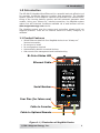
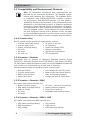
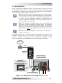
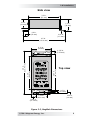
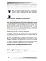
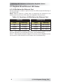
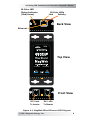
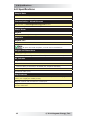
ME-MW-E
MagWeb - Wired Ethernet
Owner’s Manual
YOUR D'EhDEZ'z DISTRIBUTOR
SOLIGENT
800-967-6917
www.soligent.net
Disclaimer of Liability
The use of this manual and the conditions or methods of installation, operation, use, and maintenance of the ME-MW-E (MagWeb) is beyond the control of
Magnum Energy, Inc. Therefore, this company assumes no responsibility and
expressly disclaims any liability for loss, damage or expense whether direct,
indirect, consequential, or incidental that may arise out of or be in anyway
connected with such installation, operation, use, or maintenance.
Due to continuous improvements and product updates, the images shown in
this manual may not exactly match the unit purchased.
Restrictions on Use
The ME-MW-E may only be used in life-support devices or systems with the
express written approval of Magnum Energy. Failure of the ME-MW-E can
reasonably be expected to cause the failure of that life-support device or
system, or to affect the safety or effectiveness of that device or system. If
the ME-MW-E fails, it is reasonable to assume that the health of the user or
other persons may be endangered.
IMPORTANT PRODUCT SAFETY INSTRUCTIONS
This manual contains important safety instructions that must be followed
during the installation and operation of this product. Read all instructions
and safety information contained in this manual before installing or using
this product.
• All electrical work must be performed in accordance with local, state,
and federal electrical codes.
• This product is designed for indoor/compartment installation. It must
not be exposed to rain, snow, moisture, or liquids of any type.
• Use insulated tools to reduce the chance of electrical shock or accidental short circuits.
• Remove all jewelry such as rings, watches, bracelets, etc., when installing
or performing maintenance on the ME-MW-E and the inverter system.
• Always disconnect the batteries or energy source prior to installing or
performing maintenance on the ME-MW-E and the inverter system. Live
power may be present at more than one point since an inverter utilizes
both batteries and AC. Turning off the inverter may not reduce this
risk. As long as AC power is connected, it will pass through the inverter
regardless of the power switch on the inverter or the ON/OFF INVERTER
pushbutton on the remote.
Safety Symbols
To reduce the risk of electrical shock, fire, or other safety hazard, the following safety symbols have been placed throughout this manual to indicate
dangerous and important safety instructions.
WARNING: This symbol indicates that failure to take a specified action could result in physical harm to the user.
CAUTION: This symbol indicates that failure to take a specified action could result in damage to the equipment.
Info: This symbol indicates information that emphasizes or
supplements important points of the main text.
i
© 2011 Magnum Energy, Inc.
Table of Contents
1.0 Introduction ..................................................................1
1.1 Product Features ...................................................................... 1
1.2 Compatibility and Measurement Channels .................................... 2
1.2.1 Inverter Only .................................................................... 2
1.2.2 Inverter + Remote ............................................................ 2
1.2.3 Inverter + Remote + BMK .................................................. 2
1.2.4 Inverter + Remote + BMK + AGS ........................................ 2
2.0 Installation....................................................................3
2.1 Required Components and Tools ................................................. 4
2.1.1 List of Supplied Components in the MagWeb Kit .................... 4
2.1.2 List of Other Required Equipment and Materials .................... 4
2.1.3 Tools Required to Install the MagWeb Kit .............................. 4
2.2 Setting Up the MagWeb Device .................................................. 4
2.2.1 Connecting MagWeb to a Local Area Network and the Internet .. 6
2.2.2 Connecting MagWeb to a Single Inverter .............................. 6
2.2.3 Connecting MagWeb to a Single Inverter and Remote Control.. 6
2.3 Configuring the Local Area Network ............................................ 6
2.4 Registering on data.magnumenergy.com ..................................... 6
3.0 Using data.magnumenergy.com ....................................6
4.0 Using LED Indicators to Determine MagWeb’s Status ....7
4.1 MagWeb Device LED Status ....................................................... 7
4.2 MagWeb Wired Ethernet LED Status ............................................ 8
4.2.1 LEDs Below the Ethernet Port ............................................. 8
5.0 Troubleshooting ..........................................................10
5.1 Troubleshooting Checklist ........................................................ 10
5.2 Troubleshooting Questions and Answers .................................... 10
6.0 Specifications ..............................................................12
7.0 Limited Warranty ........................................................13
7.1 How to Receive Repair Service ................................................. 14
© 2011 Magnum Energy, Inc.
ii
List of Figures
Figure
Figure
Figure
Figure
1-1,
2-1,
2-2,
4-1,
Illustration of MagWeb Device ............................................. 1
MagWeb System Diagram ................................................... 3
MagWeb Dimensions .......................................................... 5
MagWeb Wired Ethernet LED Diagram .................................. 9
List of Tables
Table 4-1, MagWeb Device’s LED Indicator Guide ................................... 7
Table 4-2, Functions of LEDs Below the Ethernet Port ............................. 8
iii
© 2011 Magnum Energy, Inc.
1.0 Introduction
1.0 Introduction
The ME-MW-E (MagWeb Wired Ethernet) is a powerful and cost effective tool
for remotely monitoring Magnum inverters and accessories. The MagWeb
system connects to the Magnum network and provides live internet monitoring of the inverter, battery monitor, and the automatic generator start
module. Using your “always on” internet connection, the MagWeb system
makes live and historical conditions available via a web browser and our
data.magnumenergy.com service.
The MagWeb system uses the sensors and controllers already built into
Magnum products. There are no external sensors to install, configure, or
calibrate.
1.1 Product Features
• Wired Ethernet data link from MagWeb device to an “always on”
internet connection
• No sensors to install
• No configuration required
• Automatically detects connected devices
• Aids remote site management and troubleshooting
Bi-Color Status LED
Ethernet Cable
Serial Number
PN: ME-MW-E
SN: MW50000
Four Pins (for future use)
Cable to Inverter
Cable to Optional Remote
Figure 1-1, Illustration of MagWeb Device
© 2011 Magnum Energy, Inc.
1
1.0 Introduction
1.2 Compatibility and Measurement Channels
Info: All operational information and measurements are
provided by the connected equipment. The MagWeb system
collects and transmits this information. The MagWeb device
is compatible with RD/ME/MS/MS-PAE inverters (versions
2.6 and greater), and MM/MMS inverters (1.0 and greater).
Availability, accuracy, and resolution of the measurements are
dependent on the particular model(s) of Magnum equipment
connected. Contact Magnum Energy to determine if a particular measurement on your inverter or accessories is compatible
with the MagWeb system. Some settings and measurements
are done inside the remote control. Because of this, the data
is not transmitted externally from the remote control and the
MagWeb will not be able to monitor or display this information.
1.2.1 Inverter Only
Not all inverter models provide all measurement channels.
•
•
•
•
•
•
Inverter model and revision
Inverter stack mode
Status, including fault(s)
DC volts
DC amps
AC volts out
•
•
•
•
•
•
AC amps in and out
AC frequency
Invert and Charge LEDs
Battery temperature
Transformer temperature
FET temperature
1.2.2 Inverter + Remote
Compatible with all versions of Magnum’s Standard Remote Control
(ME-RC50), Advanced Remote Control (ME-ARC50), and Router (ME-RTR).
For PAE systems using the Magnum router, the current MagWeb firmware will
only monitor one inverter and one of each type of accessory.
Monitored data includes all standard inverter channels plus:
•
•
•
•
Remote revision
Inverter search watts
Battery size and type
Absorb done time
• Low voltage (AC and DC) cutout
• Battery type and custom absorb,
float, and equalize voltages
• Charge rate and AC input amps
1.2.3 Inverter + Remote + BMK
All inverter and remote channels and:
•
•
•
•
•
Battery Monitor revision
BMK status including fault(s)
State of charge
DC volts
DC amps
•
•
•
•
DC volts – minimum & maximum
Battery efficiency settings
Amp hours in and out
Resettable and total amp hours
1.2.4 Inverter + Remote + BMK + AGS
All inverter and remote and BMK channels and:
• AGS status including fault(s)
• AGS temperature
• AGS voltage
2
• Gen runtime
• AGS revision
• AGS start/stop settings
© 2011 Magnum Energy, Inc.
2.0 Installation
2.0 Installation
Before installing the MagWeb system, read this entire section so you can
thoroughly plan the details to ensure the overall system requirements are
accomplished. To assist in the planning and designing of your installation,
review the basic system diagram in Figure 2-1.
Info: Installations should be performed by qualified personnel, such as a licensed or certified electrician. It is the installer’s responsibility to determine which safety codes apply and
to ensure that all applicable installation requirements are
followed. Applicable installation codes vary depending on the
specific location and application.
Info: The MagWeb is plugged directly into a wired Ethernet
connection using the supplied Ethernet cable. The Ethernet
cable run is limited to 100 meters in total length. The Ethernet
cable must be connected to the Ethernet network and to the
MagWeb device before the MagWeb is connected to the inverter.
Info: Ensure that the MagWeb is connected to an “always on”
internet connection.
The MagWeb device is connected to the inverter using the supplied fourconductor remote cable. If an ME-RC50, ME-ARC50, ME-RTR, or other
remote is installed in the system, it is connected to the MagWeb device.
Power is supplied to the MagWeb device from the Magnum inverter.
Internet
Ethernet
Cable
Your
Network
MagWeb
Device
PN: ME-MW-E
SN: MW50000
Magnum Energy
Inverter/Charger
(with NETWORK port)
Optional
Remote Control
(ME- RC50 with revision ≥ 2.0,
ME-ARC50, ME-RTR )
P WR
FA U LT
CHG
IN V
,QYHUWLQJ
DC 12.6V
5A
S E L E CT
ONO
/ F F
CHARG ER
ONO
/ F F
I NVERTER
SHO RE
AG S
M ETER
SETUP
TECH
See AGS and BMK Manuals
for connection instructions
Figure 2-1, MagWeb System Diagram
© 2011 Magnum Energy, Inc.
(not to scale)
3
2.0 Installation
2.1 Required Components and Tools
2.1.1 List of Supplied Components in the MagWeb Kit
•
•
•
•
ME-MW-E Owner’s Manual
MagWeb device (with two #8 x 3/4” Phillips mounting screws)
6ft four-conductor remote (communications) cable
6ft eight-conductor CAT5 Ethernet cable
Info: The four-conductor remote cable is a twisted-pair, telephony standard with RJ11 connectors on each end. A standard telephone cable may be substituted if the supplied remote
cable cannot be used.
The eight-conductor CAT5 Ethernet cable is a standard twistedpair cable with RJ45 connectors on each end. A standard CAT5
Ethernet cable up to 100 meters may be substituted if the
supplied Ethernet cable cannot be used.
2.1.2 List of Other Required Equipment and Materials
• Magnum inverter with a network or remote port
• Ability to connect the MagWeb to an “always on” internet connection
that can support 2.5 megabytes of outgoing data per day and allows
connection to a public internet host
2.1.3 Tools Required to Install the MagWeb Kit
• #2 Phillips screwdriver
2.2 Setting Up the MagWeb Device
Mount the MagWeb device in a location that is dry and away from extreme
temperatures. Use the two supplied #8 x 3/4” screws to securely affix the
module. Allow ample room to view the MagWeb device’s LED and to access
all connectors.
CAUTION: Do not mount the MagWeb device in a closed battery
compartment, or in an area where water or any other liquid
can enter the device and cause shorting or corrosion. Failure
due to improper mounting is not covered by the warranty.
CAUTION: Before beginning the installation, ensure all AC
power is disconnected from the inverter, and all battery supply
cables are disconnected from the battery bank or switched
off with an appropriately rated circuit breaker. There should
be no flashing or lit LEDs on the Magnum inverter or on any
accessories.
CAUTION: When connecting battery power to the inverter, all
battery negative connections must be connected prior to the
battery positive connections. When removing battery power
from the inverter, the battery positive should be removed
before any battery negative connections are disconnected. This
is done to prevent any communication chips/lines from becoming the DC return path to the battery – causing permanent
damage to all connected accessories on the network.
Summation: Always ensure all battery negative circuits are
connected before connecting or disconnecting battery positive.
4
© 2011 Magnum Energy, Inc.
2.0 Installation
Side view
3.3 in.
(83 mm)
0.9 in.
(23 mm)
1.2 in.
(30 mm)
0.6 in.
(15 mm)
0.06 in.
(1.5 mm)
4.5 in.
(113.4 mm)
0.315 in.
(7.55 mm)
3.87 in.
(98.3 mm)
3.3 in.
(83 mm)
4.5 in.
(113.4 mm)
2.13 in.
(54 mm)
Top view
0.2 in.
(5.2 mm)
1.14 in.
(29.1 mm)
0.39 in.
(10 mm)
0.495 in.
(12.4 mm)
Figure 2-2, MagWeb Dimensions
© 2011 Magnum Energy, Inc.
5
2.0 Installation/3.0 Using data.magnumenergy.com
2.2.1 Connecting MagWeb to a Local Area Network and the Internet
The MagWeb should be attached to the Local Area Network (LAN)/Ethernet
network using the supplied 8-conductor CAT5 Ethernet cable. This connection
is made directly to a network access device such as a router, or through a
wall jack that connects to a network access device.
Info: The MagWeb is plugged directly into a wired Ethernet
connection using the supplied Ethernet cable. The Ethernet
cable run is limited to 100 meters in total length. The Ethernet
cable must be connected to the Ethernet network and to the
MagWeb device before the MagWeb is connected to the inverter.
Info: Ensure that the MagWeb is connected to an “always on”
internet connection.
2.2.2 Connecting MagWeb to a Single Inverter
Use the supplied four-conductor remote cable to connect the MagWeb
device’s TO INVERTER port to the Magnum inverter’s Remote port.
2.2.3 Connecting MagWeb to a Single Inverter and Remote Control
The MagWeb device, using the supplied cable, can be located near the remote
or near the inverter. To mount the MagWeb device near the inverter, route
the 6ft four-conductor remote cable from the inverter’s Remote port to the
MagWeb device’s TO INVERTER port. Use the longer 50ft cable — supplied
with the remote control — to connect the MagWeb device’s TO REMOTE port
to the remote control. To mount the MagWeb device near the remote, swap
the 6ft remote cable with the 50ft remote cable.
2.3 Configuring the Local Area Network
The MagWeb communicates with Magnum Energy’s servers by establishing an outgoing TCP/IP connection when data is received. At the default
30-second data interval, the MagWeb system will send approximately 2.5
megabytes of data per day.
By default, the MagWeb determines network configuration using DHCP or
BOOTP. This information includes the MagWeb’s LAN IP address and router
IP address. Most networks provide DHCP service and therefore the MagWeb
usually does not require any configuration.
For details on configuring the MagWeb for non-DHCP networks or for special
configurations, consult the troubleshooting section of this manual.
2.4 Registering on data.magnumenergy.com
Visit http://data.magnumenergy.com/ for up-to-date instructions on
registering and creating an account.
3.0 Using data.magnumenergy.com
Instructions for viewing data from your MagWeb device is available at:
http://data.magnumenergy.com/.
6
© 2011 Magnum Energy, Inc.
4.0 Using LED Indicators to Determine MagWeb’s Status
4.0 Using the LED Indicators to Determine the
MagWeb’s Status
There is a bi-color LED indicator on top of the MagWeb device (next to the
Ethernet port) to indicate the MagWeb’s status. When the device is first
powered up, the LED blinks red and green while going through a self-test.
Once the self-test is complete, use the table below and the LED indicator on
your device to determine the MagWeb’s operating status.
If the MagWeb device does not function correctly, use Table 4-1 to help find
a solution.
4.1 MagWeb Device LED Status
Table 4-1, MagWeb Device’s LED Indicator Guide
LED Status
OFF
Red ON, Green ON,
Red ON, Green ON
Green
ON
Meaning
Ensure the inverter has power and the cables
are correctly seated into the MagWeb device.
Power-up sequence (1-second interval
between each color). The MagWeb device is
performing a self-test – this occurs when first
connected to power.
Normal operation: the MagWeb device is
correctly transmitting and receiving with
network devices.
Remote not connected, or device is not able to
communicate with remote display.
Green
BLINKING
Red
ON
Ensure the correct cable is connected between
the MagWeb and the remote. If the remote/
router display is off, refer to the remote/router
owner’s manual for troubleshooting.
The power-up sequence failed. Contact
Magnum Energy.
No communication, or an unrecognizable
communication on the network.
Red
BLINKING
Check the remote cable; ensure it is connected correctly.
Important: Ensure the RJ11 connectors are
pushed into the correct port; you should feel/
hear a “click” when the connection is made.
© 2011 Magnum Energy, Inc.
7
4.0 Using LED Indicators to Determine MagWeb’s Status
4.2 MagWeb Wired Ethernet LED Status
4.2.1 LEDs Below the Ethernet Port
Normal operation is amber or green for the Link LED and periodic flashing of
the Activity LED.
Note: Refer to Figure 4-1 (Back View) to determine the positions of the
Activity and Link bi-color LEDs within the MagWeb’s Ethernet port.
Table 4-2, Functions of LEDs Below the Ethernet Port
Link LED
Activity LED
Color
Meaning
Color
Meaning
Off
No Link
Off
No Activity
Amber
10 Mbps
Amber
Half Duplex¹
Green
100 Mbps
Green
Full Duplex²
Note 1 - Data transfers between Magnum’s servers and the MagWeb system
can only transmit in one direction at a time (not simultaneously).
Note 2 - Data transfers between Magnum’s servers and the MagWeb system
can transmit in both directions at the same time (simultaneously).
8
© 2011 Magnum Energy, Inc.
4.0 Using LED Indicators to Determine Magweb’s Status
Bi-Color LED
Status Indicator
(Red/Green)
Bi-Color LEDs
Link
Activity
Back View
Ethernet
Top View
PN: ME-MW-E
SN: MW50000
Front View
RJ11 Jack
To Inverter
RJ11 Jack
To Remote
Figure 4-1, MagWeb Wired Ethernet LED Diagram
© 2011 Magnum Energy, Inc.
9
5.0 Troubleshooting
5.0 Troubleshooting
Info: Before using the information below to troubleshoot,
review the LED indicator guides in Tables 4-1 and 4-2.
5.1 Troubleshooting Checklist
The MagWeb system is designed to be simple to install and easy to use. Most
issues arise when a minor hook-up problem exists. Check the following items
before seeking further help:
• Is the MagWeb Wired Ethernet connected to an “always on” internet
connection?
• Did you connect the MagWeb’s Ethernet cable before connecting the
remote cable to the inverter or powering the inverter up?
• Is it attached to a DHCP network to assign the address?
• Did you check your internet connection by plugging a laptop into your
“always on” internet connection? (See instructions below)
• Is the inverter powered up and properly connected to the MagWeb
device?
• Did you refer to Tables 4-1 and 4-2 to learn what the LED signals
were communicating to you?
5.2 Troubleshooting Questions and Answers
What is this device on my network?
The MagWeb device allows remote monitoring of Magnum Energy inverters and accessories. Physically, it is a small black box with an Ethernet
cable and three LEDs.
How does it communicate?
When the first data is received from the MagWeb device, a TCP/IP
connection will be opened to Magnum Energy’s data server. This connection requires very little bandwidth – about 2.5 megabytes per day.
Why can’t I see my device on data.magnumenergy.com?
The most likely cause is a firewall or router blocking outgoing network
connections. Contact your network administrator to resolve the problem.
I am a network administrator. How do I adjust network settings?
For most applications you do not need to adjust the network settings.
The MagWeb will automatically receive its network settings using DHCP
or BOOTP.
If you need to modify any settings, telnet to the device on
port 9999.
10
© 2011 Magnum Energy, Inc.
5.0 Troubleshooting
What if my MagWeb cannot connect to the internet?
Unplug the Ethernet cable from the MagWeb and plug the cable into
your laptop computer. Make sure any wireless and cell phone network
connections are turned off.
Verify that you can reboot your computer, and then use a web browser
to visit: http://data.magnumenergy.com/. If you cannot connect,
then the network connection will not work for the MagWeb. The most
likely problem is a network log-in requirement or a firewall that does not
allow outgoing data connections.
What if I still have questions?
Visit www.magnumenergy.com or call the Magnum Energy offices at
425-353-8833.
© 2011 Magnum Energy, Inc.
11
6.0 Specifications
6.0 Specifications
Sample Rate
Fixed 30 second sample interval
2,800 measurements per day
Communication - Wired Ethernet
For use with our data.magnumenergy.com service
10 or 100 megabit wired Ethernet TCP/IP V4
Power Draw
MagWeb
< 0.25 watts average from Magnum bus
Materials
MagWeb Case
Anodized aluminum
RoHS
COMPLIANT
All parts are RoHS compliant, no lead used in manufacture
Weight and Dimensions
Shipping Weight: 1 pound
Dimensions (l x w x h): 4.5” x 2.2” x 1.2” (114mm x 54mm x 30mm)
Kit Includes
MagWeb Wired Ethernet
■ Owner’s Manual
■ Remote cable (4-conductor, 6 ft twisted pair, telephone standard)
■ Mounting screws
■ Ethernet cable (6 ft)
Requirements
Access to an “always on” internet connection that is capable of sending approximately 2.5 megabytes of data per day.
Magnum inverter with a network or remote port.
Magnum ME-RC50, ME-ARC50, or ME-RTR controller when other Magnum accessories are connected.
12
© 2011 Magnum Energy, Inc.
7.0 Warranty and Service Info
7.0 Limited Warranty
Magnum Energy, Inc., warrants the ME-MW-E to be free from defects in
material and workmanship that result in product failure during normal usage,
according to the following terms and conditions:
1.
The limited warranty for this product extends for 12 months from the
product’s original date of purchase.
2.
The limited warranty extends to the original purchaser of the product
and is not assignable or transferable to any subsequent purchaser.
3.
During the limited warranty period, Magnum Energy will repair, or
replace at Magnum Energy’s option, any defective parts, or any parts
that will not properly operate for their intended use with factory new
or remanufactured replacement items if such repair or replacement is
needed because of product malfunction or failure during normal usage.
The limited warranty does not cover defects in appearance, cosmetic, decorative or structural parts or any non-operative parts. Magnum
Energy’s limit of liability under the limited warranty shall be the actual
cash value of the product at the time the original purchaser returns the
product for repair, determined by the price paid by the original purchaser. Magnum Energy shall not be liable for any other losses or damages.
4.
Upon request from Magnum Energy, the original purchaser must prove
the product’s original date of purchase by a dated bill of sale, itemized
receipt.
5.
The original purchaser shall return the product prepaid to Magnum
Energy in Everett, WA. After the completion of service under this limited
warranty, Magnum Energy will return the product prepaid to the original
purchaser via a Magnum-selected non-expedited surface freight within
the contiguous United States and Canada; this excludes Alaska and
Hawaii.
6.
If Magnum repairs or replaces a product (with either a new or remanufactured product), its warranty continues for the remaining portion of
the original warranty period or 90 days from the date of the return shipment to the original purchaser, whichever is greater. All replaced products and parts removed from repaired products become the property of
Magnum Energy.
7.
This limited warranty is voided if:
• the product has been modified without authorization
• the serial number has been altered or removed
• the product has been damaged through abuse, neglect, accident,
high voltage or corrosion
• the product was not installed and operated according to the
owner’s manual
BEFORE RETURNING ANY UNIT, CONTACT MAGNUM ENERGY FOR A
RETURN MATERIAL AUTHORIZATION (RMA) NUMBER.
© 2011 Magnum Energy, Inc.
13
7.0 Warranty and Service Info
7.1 How to Receive Repair Service
If your product requires warranty service or repair, contact either:
1.
An Authorized Service Center, which are listed on the Magnum Energy
website at:
http://www.magnumenergy.com/service/servicecenters-US.htm
2.
Magnum Energy, Inc. at:
Telephone: 425-353-8833
Fax: 425-353-8390
Email: [email protected]
If returning your product directly to Magnum Energy for repair, you must:
• return the unit in the original, or equivalent, shipping container
• receive a Return Materials Authorization (RMA) number from the
factory prior to the return of the product to Magnum Energy for
repair
• place RMA numbers clearly on the shipping container or on the
packing slip
When sending your product for service, please ensure it is properly packaged. Damage due to inadequate packaging is not covered under
warranty. We recommend sending the product by traceable and insured
service.
14
© 2011 Magnum Energy, Inc.
Magnum Energy, Inc.
2211 West Casino Rd.
Everett, WA 98204
Phone: 425-353-8833
Fax: 425-353-8390
Web: www.magnumenergy.com
PN: 64-0055 Rev A