1
5SERgS-ANUAL
0ROFESSIONAL(OME4HEATER
3AFETY)NFORMATION
.OTICES
7KHOLJKWQLQJÀDVKZLWKDUURZKHDUGZLWKLQDQHTXLODWHUDOWULDQJOHLV
LQWHQGHGWRDOHUWWKHXVHUWRWKHSUHVHQFHRIXQLQVXODWHG³GDQJHURXVYROW
DJH´ZLWKLQWKHSURGXFW¶VHQFORVXUHWKDWPD\EHRIVXI¿FLHQWPDJQLWXGHWR
FRQVWLWXWHDULVNRIHOHFWULFVKRFNWRSHUVRQV
7KHH[FODPDWLRQSRLQWZLWKLQDQHTXLODWHUDOWULDQJOHLVLQWHQGHGWRDOHUW
WKHXVHUWRWKHSUHVHQFHRILPSRUWRSHUDWLQJDQGPDLQWHQDQFHVHUYLFLQJ
LQVWUXFWLRQVLQWKHOLWHUDWXUHDFFRPSDQ\LQJWKHDSSOLDQFH
:$51,1* 725('8&(7+(5,6.2)),5(25(/(&75,&6+2&.'2127(;326(7+,6
$33/,$1&(725$,12502,6785('$1*(5286+,*+92/7$*(6$5(35(6(17,16,'(7+(
(1&/2685('212723(17+(&$%,1(75()(56(59,&,1*7248$/,),('3(56211(/21/<
&ODVV%HPLVVLRQVOLPLWV
7KLV&ODVV%GLJLWDODSSDUDWXVPHHWVDOOUHTXLUHPHQWVRIWKH&DQDGLDQ,QWHUIHUHQFH&DXVLQJ
(TXLSPHQW5HJXODWLRQV
,PSRUWDQW6DIHW\,QVWUXFWLRQ
5HDGWKHVHLQVWUXFWLRQV±EHIRUHXVLQJWKLVSURMHFWRU
.HHSWKHVHLQVWUXFWLRQV±IRUIXWXUHUHIHUHQFH
)ROORZDOOLQVWUXFWLRQV
,QVWDOOLQDFFRUGDQFHZLWKWKHPDQXIDFWXUHU¶VLQVWUXFWLRQV
$'RQRWEORFNDQ\YHQWLODWLRQRSHQLQJV
7RHQVXUHUHOLDEOHRSHUDWLRQRIWKHSURMHFWRUDQGWRSURWHFWLWIURPRYHUKHDWLQJSXWWKH
SURMHFWRULQDSRVLWLRQDQGORFDWLRQWKDWZLOOQRWLQWHUIHUHZLWKLWVSURSHUYHQWLODWLRQ)RU
H[DPSOHGRQRWSODFHWKHSURMHFWRURQDEHGVRIDFDUSHWRUVLPLODUVXUIDFHWKDWPD\EORFN
WKHYHQWLODWLRQRSHQLQJV'RQRWSXWLWLQDQHQFORVXUHVXFKDVDERRNFDVHRUDFDELQHWWKDW
PD\NHHSDLUIURPÀRZLQJWKURXJKLWVYHQWLODWLRQRSHQLQJV
%'RQRWXVHWKLVSURMHFWRUQHDUZDWHURUPRLVWXUH 7RUHGXFHWKHULVNRI¿UHRUHOHFWULF
VKRFNGRQRWH[SRVHWKHSURMHFWRUWRUDLQRUPRLVWXUH
&'RQRWLQVWDOOQHDUDQ\KHDWVRXUFHV VXFKDVUDGLDWRUVKHDWHUVVWRYHVRURWKHUDSSDUDWXV
LQFOXGLQJDPSOL¿HUVWKDWSURGXFHKHDW
&OHDQRQO\ZLWKDGU\FORWK
2QO\XVHDWWDFKPHQWVDFFHVVRULHVVSHFL¿HGE\WKHPDQXIDFWXUHU
5HIHUDOOVHUYLFLQJWRTXDOL¿HGVHUYLFHSHUVRQQHO6HUYLFLQJLVUHTXLUHGZKHQWKHSURMHFWRUKDV
EHHQGDPDJHGLQDQ\ZD\
Ů 6XFKDVSRZHUVXSSO\FRUGRUSOXJLVGDPDJHG
Ů /LTXLGKDVEHHQVSLOOHGRUREMHFWVKDYHIDOOHQLQWRWKHDSSDUDWXV
Ů 7KHSURMHFWRUKDVEHHQH[SRVHGWRUDLQRUPRLVWXUHGRHVQRWRSHUDWHQRUPDOO\RUKDVEHHQ
GURSSHG
'RQRWDWWHPSWWRVHUYLFHWKLVSURMHFWRU\RXUVHOI2SHQLQJRUUHPRYLQJFRYHUVPD\H[SRVH\RX
WRGDQJHURXVYROWDJHVRURWKHUKD]DUGV3OHDVHFDOO2SWRPDWREHUHIHUUHGWRDQDXWKRUL]HG
VHUYLFHFHQWHUQHDU\RX
'RQRWOHWREMHFWVRUOLTXLGVHQWHUWKHSURMHFWRU±DVWKH\PD\WRXFKGDQJHURXVYROWDJHSRLQWV
RUVKRUWRXWSDUWVWKDWFRXOGUHVXOWLQD¿ UHRUHOHFWULFVKRFN
6HHSURMHFWRUHQFORVXUHIRUVDIHW\UHODWHGPDUNLQJV
7KHSURMHFWRUVKRXOGQRWEHDGMXVWHGRUUHSDLUHGE\DQ\RQHH[FHSWSURSHUO\TXDOL¿HGVHUYLFH
SHUVRQQHO
'R
Ů 7XUQRIIWKHSURGXFWEHIRUHFOHDQLQJ
Ů 8VHDVRIWFORWKPRLVWHQHGZLWKPLOGGHWHUJHQWWRFOHDQWKHGLVSOD\KRXVLQJ
'LVFRQQHFWWKHSRZHUSOXJIURP$&RXWOHWLIWKHSURGXFWLVQRWEHLQJXVHGIRUDORQJSHULRGRIWLPH
Ů 'RQ¶W
Ů %ORFNWKHYHQWLODWLRQVORWVDQGRSHQLQJVRQWKHXQLW
Ů 8VHDEUDVLYHFOHDQHUVZD[HVRUVROYHQWVWRFOHDQWKHXQLW
Ů 8VHXQGHUWKHIROORZLQJFRQGLWLRQV
,QH[WUHPHO\KRWFROGRUKXPLGHQYLURQPHQWV
,QDUHDVVXVFHSWLEOHWRH[FHVVLYHGXVWDQGGLUW
1HDUDQ\DSSOLDQFHWKDWJHQHUDWHVDVWURQJPDJQHWLF¿HOG
,QGLUHFWVXQOLJKW
.OTICES
3OHDVHIROORZDOOZDUQLQJVSUHFDXWLRQVDQGPDLQWHQDQFHDV
UHFRPPHQGHGLQWKLVXVHU¶VJXLGH
Ů :DUQLQJ 'RQRWORRNLQWRWKHSURMHFWRU¶VOHQVZKHQWKHODPSLVRQ7KHEULJKWOLJKWPD\
KXUW\RXUH\HV
Ů :DUQLQJ 7RUHGXFHWKHULVNRI¿UHRUHOHFWULFVKRFNGRQRWH[SRVHWKLVSURMHFWRUWRUDLQRU
PRLVWXUH
Ů :DUQLQJ 3OHDVHGRQRWRSHQRUGLVDVVHPEOHWKHSURMHFWRUDVWKLVPD\FDXVHHOHFWULFVKRFN
Ů :DUQLQJ :KHQUHSODFLQJWKHODPSSOHDVHDOORZXQLWWRFRROGRZQDQGIROORZDOO
UHSODFHPHQWLQVWUXFWLRQV6HHSDJH
Ů :DUQLQJ 7KLVSURMHFWRUZLOOGHWHFWWKHOLIHRIWKHODPSLWVHOI3OHDVHEHVXUHWRFKDQJHWKH
ODPSZKHQLWVKRZVZDUQLQJPHVVDJHV
Ů :DUQLQJ 5HVHWWKH³/DPS5HVHW´IXQFWLRQIURPWKHRQVFUHHQGLVSOD\2SWLRQV_/DPS
6HWWLQJV´PHQXDIWHUUHSODFLQJWKHODPSPRGXOHUHIHUWRSDJH
Ů :DUQLQJ :KHQVZLWFKLQJWKHSURMHFWRURIISOHDVHHQVXUHWKHFRROLQJF\FOHKDVEHHQFRP
SOHWHGEHIRUHGLVFRQQHFWLQJSRZHU$OORZVHFRQGVIRUWKHSURMHFWRUWRFRRO
GRZQ
Ů :DUQLQJ 'RQRWXVHOHQVFDSZKHQSURMHFWRULVLQRSHUDWLRQ
Ů :DUQLQJ :KHQWKHODPSLVDSSURDFKLQJWRWKHHQGRILWVOLIHWLPHWKHPHVVDJH
³5HSODFHPHQWVXJJHVWHG´ZLOOVKRZRQWKHVFUHHQ3OHDVHFRQWDFW\RXUORFDO
UHVHOOHURUVHUYLFHFHQWHUWRFKDQJHWKHODPSDVVRRQDVSRVVLEOH
%YE3AFETY7ARNINGS
Ů $YRLGVWDULQJGLUHFWO\LQWRWKHSURMHFWRUEHDPDWDOOWLPHV
Ů 0LQLPL]HVWDQGLQJIDFLQJLQWRWKHEHDP.HHS\RXUEDFNWRWKHEHDPDVPXFKDVSRVVLEOH
Ů $VWLFNRUODVHUSRLQWHULVUHFRPPHQGHGWRDYRLGWKHQHHGIRUWKHXVHUWRHQWHUWKHEHDP
Ů (QVXUHWKDWSURMHFWRUVDUHORFDWHGRXWRIWKHOLQHRIVLJKWIURPWKHVFUHHQWRWKHDXGLHQFH
WKLVHQVXUHVWKDWZKHQSUHVHQWHUVORRNDWWKHDXGLHQFHWKH\GRQRWDOVRKDYHWRVWDUHDW
WKHSURMHFWRUODPS7KHEHVWZD\WRDFKLHYHWKLVLVE\FHLOLQJPRXQWLQJUDWKHUWKDQÀ RRURU
WDEOHPRXQWLQJWKHSURMHFWRU
Ů :KHQSURMHFWRULVXVHGLQDFODVVURRPDGHTXDWHO\VXSHUYLVHVWXGHQWVZKHQWKH\DUHDVNHG
WRSRLQWRXWVRPHWKLQJRQWKHVFUHHQ
Ů ,QRUGHUWRPLQLPL]HWKHODPSSRZHUQHHGHGXVHURRPEOLQGVWRUHGXFHDPELHQWOLJKWOHYHOV
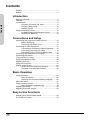
Contents
Preface .............................................................................. 1
Notices .............................................................................. 2
Introduction
Contents
Package Contents ............................................................. 7
Features ............................................................................ 8
Components ...................................................................... 9
Projector (Front and Top View) ............................. 9
Projector (Rear View) .......................................... 10
Remote Control ................................................... 11
Using the Remote Control ............................................... 12
Available Range of the Remote Control .............. 12
Inserting the Batteries ......................................... 12
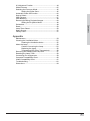
Connections and Setup
Connecting the Projector to Other Devices ..................... 14
Before Setting Up ................................................ 14
Connecting the Power Cord ................................ 14
Connecting to Video Equipment ...................................... 15
Connecting to Component Video Equipment ...... 16
Connecting Using the DVI Cable ........................ 16
Connecting Using a DVI-D to HDMI Cable.......... 17
Connecting the Projector to a Computer ......................... 18
Connecting the Cables .................................................... 19
“Plug and Play” Function ................................................. 19
Using the Adjustment Feet .............................................. 20
Adjusting the Lens ........................................................... 21
Using the Lens Shift ........................................................ 21
Setting up the Screen ...................................................... 22
Screen Size and Projection Distance .................. 23
Projection from behind the screen ...................... 25
Basic Operation
Image Projection ............................................................. 28
Basic Procedure .................................................. 28
Selecting the On-screen Display Language ........ 30
Menu Bar Items ............................................................... 31
Using the Menu Screen ................................................... 33
Menu Selections (Adjustments) .......................... 33
Adjusting the Image......................................................... 34
Adjusting Computer Images ............................................ 38
Easy to Use Functions
Selecting the Picture Display Mode................................. 40
H-V Position Function...................................................... 43
4
# O N TE N TS
+9.H\VWRQH)XQFWLRQ :KLWH(QKDQFH 6HOHFWLQJWKH(FRQRP\0RGH 6HWWLQJWKH3RZHU6DYH $XWRPDWLF3RZHU2II)XQFWLRQ 6RXUFH6HOHFW 26'7LPHRXW 26'%OHQGLQJ 5HYHUVLQJ,QYHUWLQJ3URMHFWHG,PDJHV 6HWWLQJWKH3URMHFWLRQ0RGH 'HLQWHUODFH 5HVHW /DPS7LPHU5HVHW 6WDWXV6FUHHQ )DFWRU\UHVHW !PPENDIX
0DLQWHQDQFH &OHDQLQJWKH9HQWLODWLYH+ROHV &OHDQLQJWKH9HQWLODWLYH+ROHV $ERXWWKH/DPS &DXWLRQ&RQFHUQLQJWKH/DPS 5HSODFLQJWKH/DPS 7HPSHUDWXUH/('2YHU7HPSHUDWXUH 5HPRYLQJDQG,QVWDOOLQJWKH/DPS8QLW 5HVHWWLQJWKH/DPS7LPHU &RQQHFWLQJ3LQ$VVLJQPHQWV &RPSXWHU&RPSDWLELOLW\&KDUW 9LGHR&RPSDWLELOLW\&KDUW 7URXEOHVKRRWLQJ 'LPHQVLRQV Introduction
Introduction
6
Package Contents
Open the package and ensure that you have the following items:
Strandard Accessories
Remote Control
Two “AA” Batteries
Power Cord
Composite Video Cable (3M)
Component Video Cable (3M)
RS-232C cable 3M
I n tr o d u c ti o n
Optional Accessories
HD 15-pin VGA to HD 15-pin VGA cable
RS-232C cable (3M)
DVI-D to DVI-D cable (3M)
DVI-D to HDMI cable (3M)
Ceiling mount package
Note
• Some of the cables may not be available depending on the region. Please check with
your nearest authorized dealer.
If anything is missing or appears damaged, contact your dealer immediately.
7
Features
Introduction
• Newly developed DMD™ chip provides significantly improved optical efficiency and excellent
contrast ratio.
• Newly developed LVDS (Low voltage differential signal) chip eliminates color breaking
phenomena common with previous generation DLP™ projectors.
• The 250W high-output lamp gives high color purity and brightness. Natural images are
possible with excellent color reproduction and powerful expression capabilities.
• Latest image quality circuitry gives you vivid images.
• New I/P conversion algorithm enhances motion.
• Extensive improvements in jagged edges and slanted lines in moving images.
• New Edge Up-Scaling.
• As a result of reducing jagged edges and flickering when up-scaling edges of slanted lines,
even signals not reaching a panel resolution of 480I/P can be projected by converting them to
1280 × 720 resolution images.
• New Film mode.
• 3:2 pull-down enhancement for 480I, 576I and HDTV 1080I signals.
• Use of a DVI/HDCP terminal enables all processes from input to signal processing and
projecting to be performed digitally. All-digital projection does not suffer the data loss of
analog conversion. Home theaters using HTPC are supported.
8
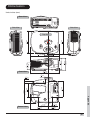
#OMPONENTS
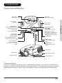
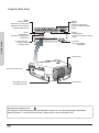
0ROJECTOR&RONTAND4OP6IEW
&OCUSRING
:OOMRING
$GMXVWVIRFXV
$GMXVWVVFUHHQGLVSOD\
)RFXV
=RRP
,ENSSHIFTDIAL
6ERTICAL
/(166+,)7
9
3UHVVWRVHWVHOHFWHGLWHPVRU
DGMXVWPHQWVLQWKHPHQX
/(166+,)7
(17(5
67$786
0(18
(;,7
(&2
%#/BUTTON
)RUSRZHUVDYLQJ
H[WHQGHGODPSOLIH
!DJUSTMENTBUTTONS
3UHVVWRVHOHFWPHQXLWHPV
%XITBUTTON
3UHVVWRH[LWWKH26'
+
,1387
4EMPERATUREINDICATOR
5HGLQGLFDWHVWKHWHPSHUDWXUHRI
WKHSURMHFWRUH[FHHGVWKHVHW
FULWLFDOWHPSHUDWXUHRUZKHQWKH
IDQPDOIXQFWLRQV
0OWER/./&&BUTTONS
3UHVVWRWXUQWKHSRZHURQRU
RII
0OWERINDICATOR
"LUE 6WDQGE\PRGH
"LUEFLASHING 7KHIDQLV
FRROLQJ
-%.5BUTTON
3UHVVWRRSHQWKH26'
PHQX
).054BUTTON
3UHVVWRVHOHFWWKHLQSXW
VRXUFH
)NTAKEVENT
%XHAUSTVENT
!DJUSTMENTFOOT
2EMOTECONTROLSENSOR
!DJUSTMENTFOOT
4EMPERATUREINDICATOR
2QWKHWRSLQSURMHFWRUFRQWUROSDQHOWKHUHLVDWHPSHUDWXUHZDUQLQJ/(',IWKHSURMHFWRURYHUKHDWVGXHWRD
GLUW\ILOWHURURWKHULVVXHWKH/('ZLOOIODVKDQGWKHODPSZLOOVKXWRII)ROORZLQJDVHFRQGFRROLQJRIISHULRG
SOHDVHUHVWDUWWKHSURMHFWRU,IWKHXQLWVWLOOLVQRWRSHUDWLQJQRUPDOO\WKHXQLWZLOOUHTXLUHLPPHGLDWHVHUYLFH
) N TR O D U C TI O N
%.4%2BUTTON
,ENSSHIFTDIAL
(ORIZONTAL
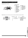
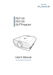
0ROJECTOR2EAR6IEW
)NPUT
6IDEO36IDEO
)NPUT
$6)0#
7HUPLQDOIRUFRQQHFWLQJYLGHR
HTXLSPHQWZLWKDQ6YLGHRRU
&RPSRVLWH9LGHRWHUPLQDO
7HUPLQDOIRU'LJLWDO9LGHR
,QWHUIDFHFRPSXWHUDQG5*%
VLJQDOV
9,'(2
69,'(2
)NPUT
#OMPONENT
3E&E
<
3U&U
3E&E
<
3&
56
7HUPLQDOVIRUFRPSRQHQWDQG
<3E3U<&E&U
:$51,1*
v
v
v
v
v
23#TERMINAL
) N TR O D U C TI O N
3U&U
0DGHLQ7DLZDQ
'9,
)NPUT
#OMPONENT
7HUPLQDOVIRUFRPSRQHQW<3E3U
<&E&U
'RQRWGLVDVVHPEOHDQ\FRPSRQHQWVH[FHSWWKHODPSFKDVVLVFRYHUZKLOHUHSODFLQJWKHODPS
'RQRWWRXFKYHQWLODWLRQVORWVODPSDQGREMHFWVQH[WWRWKHPXQWLOWKH\KDYHVXIILFLHQWO\FRROHGGRZQ
1HYHULQVHUWDQ\REMHFWVWKURXJKYHQWLODWLRQKROHV
'RQRWXVHWKLVXQLWQHDUZDWHURULQDUDLQ\PRLVWHQYLURQPHQW
.HHSDWOHDVWIRRWFPRIVSDFHEHWZHHQYHQWLODWLRQVORWVDQGQHDUHVWREMHFWRUZDOO
!#SOCKET
)LUPZDUHXSJUDGH
FRPPDQGFRQWURO
,QSXWa9$&
$+]
%XHAUSTVENT
9,'(2
69,'(2
3U&U
2EMOTECONTROLSENSOR
3E&E
<
3U&U
3E&E
<
3&
56
:$5
1,1
' 9,
*
v 'R
v ' R Q R W G L V
v 1 H Q R W W R XD V V H P E O H
v ' RY H U L Q V HF K Y H Q W L O D Q \ F R P
v . H Q R W X V HU W D Q \ R ED W L R Q V O R S R Q H Q W
HSD WKLV MHFWV WVOD VH[F
WOHD XQLW WKUR PSD HSWW
VW QHDU XJK
K
I R R Z D W Y H Q WQ G R E M H F H O D P S W HURU LODWLR WVQH FKDVV
FP LQD QKR [WWR
W K H PL V F R Y H U RIV UDLQ\ OHV
SDFH PR
0DGH
XQWL ZKLOH
EHWZ LVWHQ
OWKH UHSO
LQ7
DLZD
\KD DFLQJ
HHQ YLURQ
YHVX WKH
Q
YHQW
L O D W L RP H Q W IILF L H ODP S
QVOR
QWO\ WVDQ
FRROH
GQH
GGR
DUHV
ZQ
WREM
HFWR
UZD
OO
+ENSINGTON3ECURITY
3TANDARDCONNECTOR
%XHAUSTVENT
5SINGTHE+ENSINGTON,OCK
7KLVSURMHFWRUKDVD.HQVLQJWRQ6HFXULW\6WDQGDUGFRQQHFWRUIRUXVHZLWKD.HQVLQJWRQ0LFUR6DYHU
6HFXULW\6\VWHP7RXVHWKLVVHFXULW\IHDWXUHSOHDVHUHIHUWR\RXU.HQVLQJWRQ/RFN
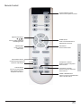
2EMOTE#ONTROL
0OWER/./&&BUTTON
3UHVVWRWXUQWKHSRZHURQDQGRII
!DJUSTMENTBUTTONS
3UHVVWRGLVSOD\DGMXVWPHQW
DQGVHWWLQJVFUHHQV
-%.5BUTTON
3UHVVWRRSHQWKH
26'PHQXV
%.4%2BUTTON
3UHVVWRVHWVHOHFWHGLWHPVRU
DGMXVWPHQWVLQWKHPHQX
%8)4BUTTON
3UHVVWRH[LWWKH26'
) N TR O D U C TI O N
!SPECT2ATIOBUTTON
&RQWUROVKRZWKHSURMHFWRU
UHVL]HVWKHLQSXWLPDJH
#OMPONENTBUTTON
$6)0#BUTTON
#OMPONENTBUTTON
3UHVVWRFRQQHFWD'LJLWDO
9LGHR,QWHUIDFHGHYLFHRU
FRPSXWHU
V9*$VRXUFH
3UHVVWRFRQQHFWWRFRPSRQHQW
GHYLFHVRXUFHV
3UHVVWRFRQQHFWWRFRPSRQHQW
GHYLFHVRXUFHV
6)$%/36)$%/BUTTON
3UHVVWRFRQQHFWWRDVWDQGDUG5&$
YLGHRRU6YLGHRVRXUFH
Using the Remote Control
Available Range of the Remote Control
The remote control can be used to control the
projector within the ranges shown in the
illustration.
23'(7 m)
Note
45°
• The signal from the remote control can be
reflected by the screen. You can control
the projector when it is behind you by
bouncing the signal off the screen.
I n tr o d u c ti o n
When using the remote control:
• Do not drop it, or expose it to moisture or high
temperature.
• The remote control may not function correctly
under fluorescent lamps. Operate the projector
away from fluorescent lamps.
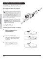
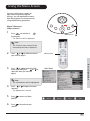
Inserting the Batteries
The batteries (two AA) are included in the package.
1
Press down the tab on the cover
and pull the cover towards the
direction of the arrow.
2
Insert the included batteries.
Make sure the polarities correctly match
the
and
marks inside the battery
compartment.
3
12
Insert the lower tab of the cover
into the opening, and press down
the cover until it clicks in place.
45°
23'(7 m)
30°
30°
30°
Connections and Setup
Connections and Setup
13
Connecting the Projecto
r to Other Devices
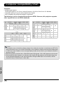
Before Setting Up
Note
• Before connecting, turn off both the projector and the devices to be connected. After making all
connections, turn on the projector first and then the other devices.
When connecting a computer, be sure that the comp uter is the last device turned on, after all
connections are made.
• Read the operation manuals of the devices to
be connected before making connections.
This projector can be connected to
Video equipment:
A VCR, Laser disc player or other video equipment.
A DVD player or DTV* decoder.
*DTV is the umbrella term used to describe the new digital television system.
Connections and Setup
A computer, using:
A HD 15-pin VGA to HD 15-pin VGA cable (sold separately), or
A DVI-D to DVI-D cable (sold separately), or
An RS-232C cable.
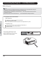
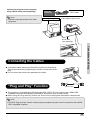
Connecting the Power Cord
Plug the supplied power cord into the AC
socket on the rear of the projector.
Supplied
accessory
Power cord
DVI
PC
Y
Pr/Cr
Pb/Cb
Y
Pr/Cr
Pb/Cb
O
S-VIDE
VIDEO
an
2
in Taiw
RS-23
Made
.
.
the lamp d down
coole
cing
repla
iently
suffic
r while
have
sis covethey
chas
until
wall.
lamp them
t or
pt the next to
est objec
ts
ts exce
near
nt.
.
objec
and
onen
onme
holes
slots
comp lamp and
lation /mois t envir
,
lation
le any
semb lation slots gh venti
a rainy een venti
ts throur or in e betw
not disas venti
wate of spac
v Do not touch any objec
t
near cm)
unit
v Do r inser
this foot (10
v Neve
0.3
not use
v Do
at least
v Keep
ING
WARN
14
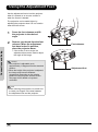
Connecting to Video Equipment
Using an S-video or a Composite Video
Cable (INPUT 3)
VCR or other video equipment
Using an S-video or a composite video cable,
a VCR, laser disc player or other video
equipment can be connected to the INPUT 3
terminals.
To S-video output terminal
To Video output terminal
DVI
PC
Y
Pb/Cb
Pr/Cr
Y
Pb/Cb
Pr/Cr
S-VIDEO
VIDEO
RS-232
Made
in Taiwan
the lamp. down.
replacing ly cooled
while
sufficient
co er
ha e
they
chassis
until
the lamp to them
or wall.
next
nts except
object
.
compone and objects
holes.
ironment and nearest
ble any slots, lamp
slots
entilation moist en
not disassem
rainy
entilation through
entilation
in a
v Do
between
not touch any objects water or
v Do
near
insert
of space
e er
this unit
( 0 cm)
v
not use
0.3 foot
v Do
at least
eep
v
NING
WAR
Notes
Composite video cable
S-video cable (sold
separately)
PC
Y
Pr/Cr
Pb/Cb
Y
Pr/Cr
Pb/Cb
O
S-VIDE
VIDEO
2
RS-23
N
WAR
v
v
v
v
v
M ad
Ta iw
e in
an
p.
.
e la m
do wn
in g th co ol ed
re pl ac en tly
wh ile e su ffi ci
co er
ha
as si s til th ey
p ch
un
ll.
m
la
wa
em
th
or
th e
je ct
ce pt s ne xt to
s ex
es t ob
ct
t.
ne nt
ob je le s.
ne ar
nm en
m po
an d
an d
y co
la m p til at io n hooi st en iroio n sl ot s
bl e an
ot s,
ss em at io n sl ro ug h en a ra in y m n en til at
t di sa
in
en til ct s th
tw ee
je
Do no t to uc h
te r or ac e be
ob
wa
y
sp
Do no in se rt an un it ne ar cm ) of
e er us e th is fo ot ( 0
t
0. 3
Do no at le as t
ee p
ING
15
Connections and Setup
• The INPUT 3 (S-VIDEO) terminal uses a
video signal system in which the picture is
separated into color and luminance signals
to give a higher-quality image. To view the
higher-quality image, use a commercially
available S-video cable to connect the
INPUT 3 terminal on the projector and the
S-video output terminal on the video
equipment.
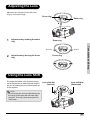
Connecting to
Component
Video Equipment
To analog component
output terminal
Using a Component Cable (INPUT 1 or 2)
DVI
PC
Y
Pb/Cb
Pr/Cr
Y
Pb/Cb
Pr/Cr
S-VIDEO
VIDEO
RS-232
the lamp. down.
replacing tly cooled
while
sufficien
co er
ha e
chassis until they
the lamp to them
or wall.
next
nts except
object
objects
.
compone and
nearest
holes.
and
ble any slots, lamp
en ironment
slots
entilation moist
entilation
not disassem
entilation through in a rainy
v Do
or
between
not touch any objects water
v Do
near
of space
insert
unit
e er
this
( 0 cm)
v
not use
0.3 foot
v Do
at least
eep
v
Use a component cable when connecting
component video equipment such as DVD
players and DTV* decoders to the INPUT 1 or
2 terminals.
*DTV is an umbrella term used to describe the
new digital television system.
Made
in Taiwan
NING
WAR
DVD player or
DTV* decoder
Component cable
DVI
PC
Note
Y
Pr/Cr
Pb/Cb
Y
• When connecting the projector to video
equipment in this way, set “Input Source” to
“Component 1 or 2” in the “Main” menu.
Pr/Cr
Pb/Cb
O
S-VIDE
EO
RS-232
Ma de
wa
in Tai
n
p.
n.
the lam led dow
coo
lac ing
ile rep f icie ntly
er wh
e suf
s co
y ha
cha ssi
il the
lam p the m unt
ll.
or wa
ept the nex t to
s
s exc
obj ect
res t
pon ent and obj ect es.
nt.
nea
com
p
hol
iron me ts and
slo
ble any slo ts, lam ent ilat ion
ist en
y mo
ilat ion
ass em
ion
h
not dis ch ent ilat s thr oug or in a rain we en ent
ect
v Do
wa ter spa ce bet
not tou any obj
nea r
of
v Do
ins ert
uni t
cm )
e er
this
t ( 0
v
not use st 0.3 foo
v Do
t lea
Connections and Setup
NING
WAR
The device’s component jacks may be labeled Y, CB and
CR. Connect each jack as shown below.
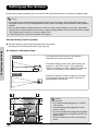
Connecting Using the DVI
Cable
Use the DVI cable when connecting video
equipment with DVI output such as DVD
players and DTV* decoders to the INPUT 4
terminal.
Projector
Y
PB
PR
DVD player or
DTV decoder
Y
CB
CR
Optional
accessory
DVI-D cable
DVD player or
DTV* decoder
DVI
PC
Y
Pb/Cb
Pr/Cr
Y
Pb/Cb
Pr/Cr
S-VIDEO
VIDEO
RS-232
Made
Note
WAR
NING
• Select the input signal type of the video
equipment.
DVI-D cable
(sold separately)
DVI
PC
Y
Pb/Cb
Pr/Cr
an
Taiw
e in
Mad
.
lamp
dow n.
g the cool ed
acin
tly
e repl icien
er whilha e suff
sis co l they
wall .
chas
unti
ct or
obje
to them
t.
nea rest
and
iron men
n slots
ilatio
16
in Taiwan
the lamp. down.
replacing ly cooled
while
sufficient
co er
ha e
they
chassis
until
the lamp to them
or wall.
next
nts except
object
.
compone and objects
holes.
ironment and nearest
ble any slots, lamp
slots
entilation moist en
not disassem
entilation through
rainy
entilation
in a
v Do
between
not touch any objects water or
v Do
near
insert
of space
e er
this unit
( 0 cm)
v
not use
0.3 foot
v Do
at least
eep
v
Connecting Using a DVI-D to
HDMI Cable
Use a DVI to HDMI cable when connecting
HDMI video equipment such as DVD players
to the INPUT 4!terminal.!
1
Optional
accessory
DVI-D to HDMI
cable
To HDMI output terminal
Connect a DVI-D to HDMI cable to
the projector.
DVI
PC
Y
Pr/Cr
Pb/Cb
Y
Pr/Cr
Pb/Cb
S-VIDEO
VIDEO
• Secure the connectors by tightening
the thumbscrews.
2
RS-232
Made
in Taiwan
the lamp. down.
replacing ly cooled
while
sufficient
cover
have
they
chassis
until
the lamp to them
or wall.
next
nts except
object
compone and objects
ent.
nearest
n holes. environm
and
ble any slots, lamp
st
n
n slots
ventilatio
not disassem
ventilatio through in a rainy/moi ventilatio
• Do
between
not touch any objects water or
• Do
near
insert
of space
unit
(10 cm)
• Never use this
not
0.3 foot
• Do
at least
• Keep
NING
WAR
Connect the above cable to the
video equipment.
Note
DVD player or
DTV* decoder
DVI-D to HDMI cable
(sold separately)
• Select the input signal type of the video
equipment.
Connections and Setup
DVI
PC
Pr/Cr
Pb/Cb
Y
an
Taiw
e in
Mad
.
lamp
dow n.
g the cool ed
acin
tly
e repl icien
r whilhave suff
sis cove
they
wall .
unti l
p chas
ct or
obje
t to them
rest
ent. and nea
slots
nvir onm
tilat ion
17
Connecting the Projector to a Computer
Connect the projector to the computer
using an HD 15-pin VGA cable.
• Secure the cable connectors by tightening
the screws on both sides of the plug.
Connections and Setup
Notes
Optional
accessory
HD 15-pin
VGA cable
Notebook Computer
• See page 60 “Computer Compatibility
Chart” for a list of computer signals
compatible with the projector. Using
computer signals other than those listed
may cause some of the functions not to
work.
• When connecting the projector to a
computer using an HD 15-pin VGA cable,
set the “Input Source” to “PC” in the “Main”
menu, or select RGB mode by pressing the
DVI/PC button on the remote control.
• A Macintosh adaptor may be required for
use with some Macintosh computers.
Contact your nearest authorized service
center or dealer.
• Depending on the computer you are using,
an image may not be projected unless the
signal output setting of the computer is
switched to the external output. Refer to the
computer operation manual for switching
the computer signal output settings.
HD 15-pin VGA cable
(sold separately)
To VGA output terminal
DVI
PC
Y
Pr/Cr
Pb/Cb
RS-232
Made
in Taiwan
the lamp. down.
replacing ly cooled
while
sufficient
cover
have
they
chassis
until
the lamp to them
or wall.
next
nts except
object
compone and objects
ent.
nearest
n holes. environm
and
ble any slots, lamp
st
n
n slots
ventilatio
not disassem
ventilatio through in a rainy/moi ventilatio
• Do
between
not touch any objects water or
• Do
near
insert
of space
unit
• Never use this foot (10 cm)
not
0.3
• Do
at least
• Keep
WAR
NING
HD 15-pin VGA cable
(commercially available)
DVI
PC
Pr/Cr
Pb/Cb
Y
Ma de
iwa
in Ta
n
p.
.
the lamole d do wn
co
lac ing
ile rep ffic ien tly
ve r wh ve su
sis co the y ha
ch as
til
ll.
m un
or wa
to the
jec t
ob
are st
me nt.
d ne
vir on slo ts an
n
ila tio
18
Pb/Cb
Y
Pr/Cr
S-VIDEO
VIDEO
Connect the projector to the computer
using a DVI-D cable (sold separately).
Optional
accessory
DVI-D cable
Note
• Select the input signal type of the video
equipment.
To DVI Digital output terminal
Desktop Computer
DVI
PC
Y
Pr/Cr
Pb/Cb
Y
Pr/Cr
Pb/Cb
S-VIDEO
VIDEO
RS-232
Made
in Taiwan
the lamp. down.
replacing ly cooled
while
sufficient
cover
have
they
chassis
until
the lamp to them
or wall.
next
nts except
object
compone and objects
ent.
nearest
n holes. environm
and
ble any slots, lamp
st
n
n slots
ventilatio
not disassem
ventilatio through in a rainy/moi ventilatio
• Do
between
not touch any objects water or
• Do
near
insert
of space
unit
(10 cm)
• Never use this
not
0.3 foot
• Do
at least
• Keep
WAR
NING
DVI-D cable
(sold separately)
Connections and Setup
DVI
PC
Pr/Cr
Pb/Cb
Y
Y
an
Taiw
e in
Mad
lam p. dow n.
g the coo led
repl acin
icie ntly
whi le e suff
hav
cov er
they
ssis
wal l.
unti l
p cha
ct or
obje
the lamt to them
nex
t.
nea rest
ects s.
men
and
hole env iron slot s
moi stven tilat ion
n
wee
Connecting the Cables
Connect the cable making sure that it fits correctly into the terminal.
Secure the connectors by tightening the screws on both sides of the
plug.
Do not remove the ferrite cores attached to the cable.
DVI
PC
Pr/Cr
Pb/Cb
Y
Mad e
in Taiw
an
.
the lamped dow n.
acin g
tly cool
e repl
r whil
suffi cien
have
sis cove
they
mp chas
until
them
wall .
xt to
ct or
est obje
ent.
near
envi ronm slots and
ntila tion
“Plug and Play” Function
Ferrite cores
This projector is compatible with VESA-standard DDC 1/DDC 2B. The projector and a VESA DDC
compatible computer automatically send settings, allowing for quick and easy setup.
Before using the “Plug and Play” function, be sure to turn on the projector first and the computer last.
Note
• The DDC “Plug and Play” function of this projector operates only when used in conjunction with a VESA
DDC compatible computer.
19
Using the Adjustment Feet
Use the adjustment feet to level the projector
when it is placed on an uneven surface or
when the screen is slanted.
Connections and Setup
The projection can be made higher by
adjusting the projector when it is in a location
lower than the screen.
1
Press the foot releases and lift
the projector to the desired
angle.
2
Remove your hands from the foot
releases. When the adjustment
feet have locked in position,
place the projector down.
Foot releases
• If the screen is at an angle, the
adjustment feet can be used to adjust
the angle of the image.
Notes
• The projector is adjustable up to
approximately 11 degrees from the standard
position.
• When the height of the projector is adjusted,
the image may become distorted
(keystoned), depending on the relative
positions of the projector and the screen.
See page 44 for details on keystone
correction.
Info
• When lowering the projector, be careful not
to catch your fingers in the area between
the adjustment foot and the projector.
20
Adjustment feet
Adjusting the Lens
Adjust the lens using the focus and zoom
rings to correct the image.
Focus ring
Focus
Zoom
1
Adjust zoom by rotating the zoom
ring.
Zoom ring
Adjust focus by moving the focus
ring.
Connections and Setup
Zoom in
Zoom out
2
Zoom ring
Focus ring
Using the Lens Shift
The height and width of the projected image
can be adjusted to be within the shift range of
the lens by rotating the lens shift dial at the top
of the projector.
Lens shift dial
(Vertical)
Lens shift dial
(Horizontal)
Note
• Do not forcibly turn the lens shift dial beyond
the range of the upper left and lower right
positions. This may cause the projector to
malfunction.
21
Setting up the Screen
Position the projector perpendicular to the screen with all feet flat and level to achieve an optimal image.
Notes
• The projector lens should be perpendicular (square-on) to the screen. If the horizontal line passing
through the lens center is not perpendicular to the screen, the image will be distorted, making viewing
difficult.
• For an optimal image, position the screen so that it is not in direct sunlight or room light. Light falling
directly on the screen washes out the colors, making viewing difficult. Close curtains and dim the lights
when setting up the screen in a sunny or bright room.
• A polarizing screen cannot be used with this projector.
Standard Setup (Front Projection)
An Example of Standard Setup
• The distance from the screen to the projector
depends on the size of the screen.
Side View
• The default setting can be used, when placing the
projector in front of the screen. If the projected
image is reversed or inverted, readjust the setting to
“Front” for “PRJ Mode” in the “Options” menu.
90
Audience
Top View
Focus
(V)
EXIT
ECO
ENTER
STATUS
INPUT
MENU
Zoom
LENS SHIFT
(H)
90
• Place the projector so that an imaginary horizontal
line that passes through the center of the lens is
perpendicular to the screen.
LENS SHIFT
Connections and Setup
Place the projector at the required distance from the screen
according to the desired picture size. (See page 23)
3
H
40
3
H
40
13
V
20
H
V
1
V
2
1
H
2
22
1
V
2
Notes
2D Lens Shift:
• The vertical display (Biggest) is (+13/20V / 1/2V) screen.
• The horizontal display (Biggest) is ±3/40
screen. (±15%)
• It is recommended that images be projected
onto the dashed line octagonal area for fine
image quality.
• There is a tolerance of ±3% in the formula
above.
Screen Size and Projection DistanceȮ
x
When using a wide screen (16:9) project the image on the
whole area of the 16:9 screen.
z
y
16
9
: Picture area
Screen Size (16:9)
Width
261” (664 cm)
218” (553 cm)
174” (443 cm)
131” (332 cm)
116” (294 cm)
92” (234 cm)
87” (221 cm)
80” (204 cm)
73” (186 cm)
63” (159 cm)
52” (132 cm)
35” (89 cm)
Height
Max
147" (374 cm) 37'6" (11.4 m)
123" (311 cm) 31'3" (9.5 m)
98" (249 cm) 24'12" (7.6 m)
74" (187 cm)
18'9" (5.7 m)
65" (166 cm)
16'7" (5.1 m)
52" (132 cm)
13'3" (4.0 m)
49" (125 cm)
12'6" (3.8 m)
45" (115 cm)
11'6" (3.5 m)
41" (105 cm)
10'6" (3.2 m)
35" (90 cm)
9'00" (2.7 m)
29" (75 cm)
7'6" (2.3 m)
20" (50 cm)
5'00" (1.5 m)
Min
29'10" (9.1 m)
24'11" (7.6 m)
19'11" (6.1 m)
14'11" (4.6 m)
13'3" (4.0 m)
10'7" (3.2 m)
9'11" (3.0 m)
9'2" (2.8 m)
8'4" (2.5 m)
7'2" (2.2 m)
6'00" (1.8 m)
4'00" (1.2 m)
Distance from lens center to
the lower edge of the image
upper
lower
0” (0 cm)
-12’3” (-374 cm)
0” (0 cm)
-10’3” (-311 cm)
0” (0 cm)
-8’2” (-249 cm)
0” (0 cm)
-6’2” (-187 cm)
0” (0 cm)
-5’5” (-166 cm)
0” (0 cm)
-4’4” (-132 cm)
0” (0 cm)
-4’1” (-125 cm)
0” (0 cm)
-3’9” (-115 cm)
0” (0 cm)
-3’5” (-105 cm)
0” (0 cm)
-2’11” (-90 cm)
0” (0 cm)
-2’5” (-75 cm)
0” (0 cm)
-1’8” (-50 cm)
The formula for screen size and projection distance
y1(max)=0.038089291x
y2(min)=0.030344196x
z1 (Upper) = 0
z2(lower)=1.245263549x
x: Screen size (diag.) (meter)
y: Projection distance (feet)
z: Distance from the lens center to the lower
edge of the image (centimeter)
Notes
• There is a tolerance of ±3% in the formula above.
• Values with a minus (–) sign indicate the distance of the lens center below
the bottom of the image.
23
Connections and Setup
Diagonal
300” (762 cm)
250” (635 cm)
200” (508 cm)
150” (381 cm)
133” (338 cm)
106” (269 cm)
100” (254 cm)
92” (234 cm)
84” (213 cm)
72” 183 cm)
60” (152 cm)
40” (102 cm)
Projection Distance
When using a normal screen (4:3) project the image to the full horizontal width of the 4:3 screen.
4
3
: Screen area
: Picture area
Connections and Setup
Screen Size (4:3)
Diagonal
250" (635 cm)
200" (508 cm)
150" (381 cm)
133" (338 cm)
106" (269 cm)
100" (254 cm)
92" (234 cm)
84" (213 cm)
72" (183 cm)
60" (152 cm)
40" (102 cm)
Projection Distance
Width
Height
200" (508 cm) 150" (381 cm)
160" (406 cm) 120" (305 cm)
120" (305 cm) 90" (229 cm)
106" (270 cm) 80" (203 cm)
85" (215 cm) 64" (162 cm)
80" (203 cm) 60" (152 cm)
74" (187 cm) 55" (140 cm)
67" (171 cm)
50" (128cm)
58" (146 cm) 43" (110 cm)
48" (122 cm)
36" (91 cm)
32" (81 cm)
24" (61 cm)
Max
Min
28'8" (8.7 m) 22'10" (7.0 m)
22'11" (7.0 m) 18'3" (5.6 m)
17'2" (5.2 m) 13'8" (4.2 m)
15'3" (4.6 m) 12'2" (3.7 m)
12'2" (3.7 m)
9'8" (3.0 m)
11'6" (3.5 m)
9'2" (2.8 m)
10'7" (3.2 m)
8'5" (2.6 m)
9'8" (2.9 m)
7'8" (2.3 m)
8'3" (2.5 m)
6'7" (2.0 m)
6'11" (2.1 m)
5'6" (1.7 m)
4'7" (1.4 m)
3'8" (1.1 m)
Distance from lens center to
the lower edge of the image
upper
lower
0” (0 cm)
-9’5” (-286 cm)
0” (0 cm)
-7’6” (-229 cm)
0” (0 cm)
-5’8” (-171 cm)
0” (0 cm)
-5’0” (-152 cm)
0” (0 cm)
-4’0” (-121 cm)
0” (0 cm)
-3’9” (-114 cm)
0” (0 cm)
-3’5” (-105 cm)
0” (0 cm)
-3’2” (-96 cm)
0” (0 cm)
-2’8” (-82 cm)
0” (0 cm)
-2’3” (-69 cm)
0” (0 cm)
-1’6” (-46 cm)
The formula for screen size and projection distance
y1 (Max.) = 0.03466592x
y2 (Min.) = 0.0276352x
z1 (Upper) = 0
z2 (Lower) = 1.143x
x: Screen size (diag.) (meter)
y: Projection distance (feet)
z: Distance from the lens center to the lower
edge of the image (centimeter)
Notes
• There is a tolerance of ±3% in the formula above.
• Values with a minus (–) sign indicate the distance of the lens center below
the bottom of the image.
24
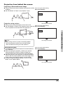
Projection from behind the screen
Projecting a Reversed/Inverted Image
Place a translucent screen between the projector and the When using the default setting.
audience.
TOn-screen Display
Set “PRJ Mode” to “Rear” in the “Options” menu.
Projection using a mirror
The image is reversed.
Place a mirror (normal flat type) in front of the lens.
When using the default setting.
Set “PRJ Mode” to “Rear” in the “Options” menu, when the TOn-screen Display
mirror is placed on the side where the audience is.
Connections and Setup
Info
The image is reversed.
• When using a mirror, be sure to carefully position
both the projector and the mirror so that the light
does not shine into the eyes of the audience.
Ceiling-mount setup
The optional ceiling-mount bracket is recommended for
this installation.
Before mounting the projector, contact your nearest
Authorized Service Center or Dealer to obtain the
recommended ceiling-mount bracket (sold separately).
Adjust the position of the projector to match the distance
(Z) from the lens center position to the lower edge of the
image, when mounting the projector on the ceiling.
Invert the image by setting “Ceiling + Front” for “PRJ
Mode” in the “Options Menu”.
When using the default setting.
TOn-screen Display
The image is reversed.
25
Connections and Setup
NOTES
26
Basic Operation
Basic Operation
27
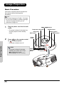
Image Projection
Basic Procedure
Connect the required external equipment to
the projector before following these
procedures.
Info
• The preset language is English. To change
the on-screen display to another language,
reset the language according to the
procedure on page 30.
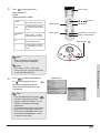
1
Plug the power cord into the wall
outlet.
• The power indicator illuminates blue,
and the projector enters standby
mode.
2
Press
or
on the remote control
T, S, W, X buttons
Temperature Indicator
ENTER button
INPUT button
ECO button
MENU button
EXIT button
Power
button
ENTER
on the projector.
• The power indicator turns off.
Basic Operation
STATUS
MENU
EXIT
Note
• The power indicator illuminates,
indicating the status of the lamp.
Blue: The power is ready.
Blue blinking: The fan is cooling.
28
Power
indicator!
(Blue)
ECO
INPUT
3
Press
on the projector to
Power button
INPUT
select the INPUT
mode.
About the INPUT modes
S-Video
Use this option to select
the S-Video input source.
Video
Use this option to select
the composite video input
source.
Component
1&2
Use this option to select a
YPbPr, SDTV, or HDTV
component input source.
DVI
Use this option to select
the DVI input source.
PC
Use this option to select
the computer as an input
source.
,
MENU button
,
,
buttons
EXIT button
Component 1 & 2 buttons
Video/ S-Video button
DVI/PC button
INPUT button
INPUT
ENTER
STATUS
MENU
EXIT
Note
ECO
INPUT
• When a signal is not received,
“Searching” will be displayed.
Note
4
Press
on the remote control
B a s i c O p e r a ti o n
• If you select “Auto” as the input
source, then the correct input source
is selected automatically.
Main Menu
or
on the projector. Press
Enter to turn off the projector,
when the confirmation message
is displayed.
Note
• If you accidentally press power
and do not want to turn off the
projector, press Exit button or wait
until the confirmation message
disappears.
• Do not unplug the power cord during
projection or cooling fan operation.
This can cause damage due to the
rise in internal temperature, as the
cooling fan also stops.
29
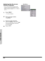
Selecting the On-screen
Display Language
Main Menu
• The on-screen display language of the
projector can be set to English, Français,
Italiano, Deutsch, Español, ʒᄾ- ᅻቐ⦞- or
ᾂ᱑ /
1
Press “MENU”.
• The menu displays.
2
Press
or X to select
“Language”.
3
Press S or T to select the
desired language, then press
The selected language is set as the
on-screen display.
Basic Operation
4
30
Press “EXIT”.
.
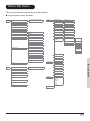
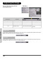
Menu Bar Items
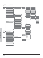
This list shows the items that can be set in the projector.
Composite Video/S-Video, DVI Mode
Picture
Picture Setting
Normal/Bright/Movie/Custom1/
Custom2
Options
White Peaking
ON/OFF
Brightness
-50 ~ +50
Bright Mode
ON/OFF
Contrast
-50 ~ +50
Auto Power Off
ON/OFF
Color
-64 ~ +64
Source Select
Tint
-64 ~ +64
OSD Timeout
5. 15. 60 secs
Softest, Soft, Normal, Sharp,
Sharpest
OSD Blending
ON/OFF
G a mma
1 . 0 /1 . 5 /1 . 8 /2 . 0 /2 . 2 /2 . 3 5 /2 . 5 /2 . 8
PRJ Mode
Front/Front ceiling/
Rear/Rear ceiling
Color Temp
Color Temp 5000k ~ 10000k,
Native
Deinterlace
(Dvi Hide)
DCTI
0~7
Video on film
ON/OFF
Film Mode
3:2@60Hz
Sharpness
x
-30 ~ +30
y
-30 ~ +30
Reset this CT
White Balance
Manual/Auto
2:2@50Hz
R
Gain
G
Gain
B
Gain
R
Offset
G
Offset
B
Offset
2:2@50Hz
3:2@60Hz
OFF
Reset
Lamp Timer Reset
Status
Input Source
S-Video
Reset
Layout
Aspect Ratio
Basic Operation
Composite
Component 1
16:9/4:3/LBX/Native
Component 2
H-Position
DVI
V-Position
PC
V-Keystone
Language
H-Keystone
Reset
English
Français
Italiano
Deutsch
Español
ਛᢥ
ᣣᧄ⺆
한국어
Factory Reset
31
PC/Component 1&2 Mode
Picture
Picture Setting
Normal/Bright/Movie/Custom1/
Custom2
White Peaking
ON/OFF
-50 ~ +50
Bright mode
ON/OFF
Contrast
-50 ~ +50
Auto Power Off
ON/OFF
Color
(PC Hide)
-64~+64
Source Select
Manual/Auto
Tint
(PC Hide)
-64~+64
OSD Timeout
5. 15. 60 secs
OSD Blending
ON/OFF
PRJ Mode
Front/Front ceiling/
Rear/Rear ceiling
Deinterlace
(480i, 576i only)
DCTI
0~7
Video on film
ON/OFF
Film Mode
3:2@60Hz
Brightness
Options
Softest, Soft, Normal, Sharp,
Sharpest
Sharpness
G a m ma
1 . 0 /1 . 5 /1 . 8 /2 . 0 /2 . 2 /2 . 3 5 /2 . 5 /2 . 8
Color Temp
Color Temp 5000k ~ 10000k,
Native
x
y
-30 ~ +30
-30 ~ +30
2:2@50Hz
Reset this CT
White Balance
2:2@50Hz
3:2@60Hz
R
Gain
G
Gain
B
Gain
R
Offset
Lamp Timer Reset
G
Offset
Status
B
Offset
OFF
Reset
Input Source
S-Video
Composite
Reset
Component 1
Basic Operation
Fine Sync
Clock
-50 ~ +50
(Component 1/2 Hide)
Component 2
Phase
DVI
-16 ~ +15
Reset
PC
Execute Auto Tune
Language
Auto Tune (ON/OFF)
Layout
Aspect Ratio
16:9/4:3/LBX/Native
H-Position
V-Position
V-Keystone
H-Keystone
Reset
32
Factory Reset
English
Français
Italiano
Deutsch
Español
ਛᢥ
ᣣᧄ⺆
한국어
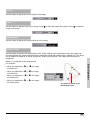
Using the Menu Screen
You can use the menu screens to
adjust the image and projector
settings. You can operate the menus
from the projector or remote control
using the following procedure.
Menu Selections
(Adjustments)
ENTER
STATUS
MENU
EXIT
ECO
1
Press
on remote or
INPUT
on
MENU button
MENU
the keypad.
MENU
• The menu screen is displayed.
Note
• The “Picture” menu screen for the
selected input mode is displayed.
Press
or
to select the menu
you want to adjust.
MENU button
3
Press
or
to reach the Submenu and then press
or
to
select the item you want to
adjust.
Main Menu
B a s i c O p e r a ti o n
2
Note
• The selected item will be highlighted.
4
Press
or
selected.
to adjust the item
• The adjustment is stored.
5
Press
to return to “Main
MENU”.
6
Press
to close the menu
screen.
33
Adjusting the Image
You can adjust the image with the
following procedure.
Selected item
Brightness
Main Menu
Description
Adjusts the brightness
Decreases brightness
Increases brightness
Contrast
Adjusts the contrast level
Decreases contrast
Increases contrast
Color
Adjusts the color intensity
Decreases color intensity
Increases color intensity
Adjusts the tones
Skin tones become purplish
Skin tones become
greenish
Tint
Basic Operation
Brightness
Use this option to adjust the overall brightness of the image. Use in conjunction with contrast to fine-tune the
display. The scale is from -50 to 50.The default setting is 0.
Contrast
Use this option to adjust the contrast of the image. Use this control in conjunction with contrast to fine-tune
the display. The scale is from -50 to 50. The default setting is 0.
34
Color
Use this option to adjust the color intensity of the image.
Tint
Use this option to adjust the tint of your image. Press X to make the image more green. Press W to make the
image more purple.
Sharpness
Use this option to adjust the clarity and focus of the image.
Color TEMP
Use this option to set the color temperature of the image. Higher color temperatures make the image look
cool with a bluish hue. Lower color temperature makes the image look warmer with a reddish hue. The range
is from 5000°K to 10000°K, in 500°K increments. When set to "NATIVE", the image has the maximum
brightness.
Basic Operation
Select x, y to adjust the color temperature.
For example:
• When you adjust the x, X, y, W, the image
will looks red.
• When you adjust the x,W, y, W, the image
will looks blue.
• When you adjust the x, W, y, X, the image
will looks green.
• When you adjust the x, X, y, X, the image
will looks yellow.
The point will move in the
Black Body Curve.
35
Gamma
Use this option to adjust the gamma correction of the image. There are seven non-linear gamma corrections
1.0, 1.5, 1.8, 2.0, 2.2, 2.35, 2.5, and 2.8. The default setting is 2.2.
White Balance
Basic Operation
The contrast and brightness for each color of the RGB Gain & Offset values in DLP can be individually
adjusted.
36
Picture setting
This function stores Brightness, Contrast,
Color, Tint, Sharpnes s, Gamma, Color Temp,
Color Type, and White Enhance set in
“Picture”. Each stored se tting is reassigned to
each input mode.
Select “Picture Setting” from the “Picture” menu on the menu screen.
For operating the menu screen, see page 33.
Note
• When Recalling Saved Contents:
When a saved memory number is selected,
the contents of the “Picture” menu changes
to the adjustment values of the saved
memory number.
• When Editing Saved Contents:
Edit the contents of the “Picture” menu after
selecting the memory number for which
adjustment values are to be edited.
Reset
Select this option to set to all items in the "Picture"
menu to the factor y default values.
Basic Operation
37
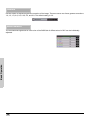
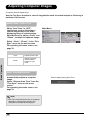
Adjusting Computer Images
(Computer Source Signal Only)
Use the Fine Sync function in case of irregularities such as vertical stripes or flickering in
portions of the screen.
When Auto Tune is OFF
When “Auto Tune” is “OFF”,
interference such as flickering or
vertical stripes may occur when
displaying tiling or vertical stripes.
Should this occur, adjust “Clock” and
“Phase”, to obtain an optimum image.
Main Menu
Basic Operation
Select “Clock”, “Phase”, in the “Fine
Sync” menu on the menu screen.
For operating the menu screen, see
page 33.
Selected item
Description
Clock
Adjusts vertical noise.
Phase
Adjusts horizontal
noise (similar to
tracking on your
VCR).
Auto Tune adjustment
Automatically adjusts a computer
image.
Select “Execute Auto Tune” from the
“Fine Sync” menu on the menu
screen.
For operating the menu screen, see
page 33.
Note
• Auto Tune may take some time to complete,
depending on the image stored in the
computer connected to the projector.
38
Screen display during Auto Tune
Easy to Use Functions
Easy to Use Functions
39
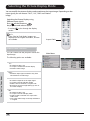
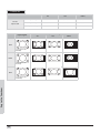
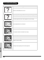
Selecting the Picture Display Mode
You can modify the picture display mode to enhance the input image. Depending on the
input signal, you can choose “16:9”, “4:3”, “LBX” and “Native”
image.
Switching the Picture Display using
Different input signals
Press
on the remote or on
the projector and select a layout.
• Pressing
modes
cycles through the display
Info
• In the Pixel to Pixel Mode, images are
displayed in the original resolution, and are
not scalable.
Aspect Ratio
Aspect Ratio Function
You can control how the projector resizes the
input image.
The following option are available:
E a s y to U s e F u n c ti o n s
16:9
• Resolution 1280 × 720
• 4:3 input is stretched to fit 16:9 display
• Stretches entire image.
Native
• Maintains input signal resolution. May have
black borders around image.
4:3
• Resolution depends on the Input Signal
• 4:3 input scaled to fit display height
• Width scaled to maintain 4:3 aspect ratio
• Black bars on left and right (taking up 25% of
the whole display)
LBX
• Resolution 1280 × 720
• 4:3 input scaled to fit display width
• Height scaled to maintain 4:3 aspect ratio:
1280 × 960
• 25% of the entire image on the top and bottom
is cropped.
40
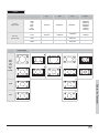
Main Menu
VIDEO
4:3
For 4:3
aspect ratio
For 16:9
aspect ratio
Input Signal
480I
480P
576I
576P
NTSC
PAL
SECAM
LBX
16:9
Native
1280X720
640X480i
640X480P
768X576i
768X576P
640X480
768X576
768X576
480i
480P
576i
576P
NTSC
PAL
SECAM
768X576
480P
576P
768X576
768X576
1280X720
1280X720
720P
–
–
1280x720
–
1080i
–
–
1280x720
–
1280X720
1280X720
720X480
720X576
Output screen image
4:3
LBX
16:9
Native
For 4:3 aspect ratio
Letter box image
Easy to Use Functions
1080I
For 16:9 aspect ratio
720P
41
COMPUTER
For 4:3
aspect ratio
4:3
16:9
VGA(640X480)
960X720
1280X720
640X480
SVGA(800X600)
960X720
1280X720
800X600
XGA(1024X768)
960X720
1280X720
1024X768
Native
.
Input Signal
VGA
For 4:3 aspect ratio
(640x480)
SVGA
For 4:3 aspect ratio
(800x600)
XGA
Easy to Use Functions
For 4:3 aspect ratio
(1024x768)
42
Output screen image
4:3
16:9
Native
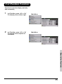
H-V Position Function
Use this to center the display vertically
and horizontally.
1
In H Position, press “W” or “X”.
The display moves left or right.
2
In V Position, press “W” or “X”
The display moves upward or
downward.
Main Menu
Main Menu
Easy to Use Functions
43
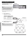
H-V Keystone Function
Correcting Trapezoidal Distortion and
Adjusting Vertical Size.
Main Menu
This function allows for Keystone correction.
Note
• When the image is projected at an angle,
the image becomes distorted trapezoidally.
The function for correcting trapezoidal
distortion is called Keystone Correction.
(On-screen Trapezoidal Distortion)
Correction and the adjustment of the vertical
size of the picture.
1
Easy to Use Functions
2
Select “V-Keystone” or
“H-Keystone” in the!layout.
Selected item
Description
H Keystone
Horizontally adjusts the
keystone settings.
V Keystone
Vertically adjusts the
keystone settings.
Press“W” or “X” to adjust the
keystone correction.
Compresses
upper side.
* “V-SIZE” is not displayed when the value
of “KEYSTONE” is “0”.
Compresses
lower side.
Note
• Straight lines or the edges of images may
appear jagged while adjusting the image.
Horizontal Keystone Correction
Vertical Keystone Correction
44
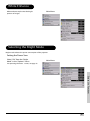
White Enhance
White enhance emphasizes the bright
portions of images.
Main Menu
Selecting the Bright Mode
Bright mode reduces the power consumption of the projector.
Setting the Power Save
Select “ON” from the “Bright
Mode” in the “Options” menu.
Main Menu
For operating the menu screen, see page 33.
Easy to Use Functions
45
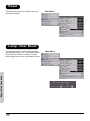
Automatic Power Off Function
When set to “ON”, the Auto Power Off
switches the projector off if an input signal is
not detected or you do not press any controls
for 15 minutes.
Main Menu
Auto Power Off is disabled when set to “OFF”.
Select “Auto Power Off” from the
“Options” menu on the menu screen.
For operating the menu screen, see
page 33.
Note
• When the Auto Power Off function is set to
“ON”, a warning, “Power OFF in 5 min.”
displays five minutes before the power turns
off.
Source Select
This selects the input source automatically if
no signal is detected on the current input.
Easy to Use Functions
Source Select
Auto
Manual
Select “source select” from the
“Options” menu on the menu screen.
For operating the menu screen, see
page 33.
46
Main Menu
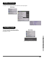
OSD Timeout
OSD Timeout is used to set how long the OSD
stays open if no buttons are pressed.
OSD Timeout
Main Menu
5
15
60
Easy to Use Functions
47
OSD Blending
This allows you to set the transparency of the OSD menu. When set to transparent, you can see the image
behind the menu.
Select “OSD Blending” from the
“Options” menu on the menu screen.
For operating the menu screen, see
page 33.
Selected item
Description
ON
OSD background will
blend
OFF
Normal
Main Menu
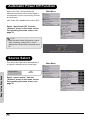
Reversing/Inverting Projected Images
The projector can reverse and invert images for various projection methods.
Setting the Projection Mode
Easy to Use Functions
Select “Projection Mode” from the
“Options” menu on the menu screen.
For operating the menu screen, see
page 33.
Selected item
Description
Front
Normal image
Ceiling + Front
Inverted image
Rear
Reversed image
Ceiling + Rear
Reversed and
inverted image
Note
• This function can be used for the reversed
image and ceiling-mount setups.
48
Main Menu
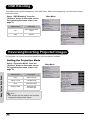
Deinterlace
There are several different deinterlacing algorithms. Choose the setting that best matches the content you
are watching.
Select “Deinterlace” from the
“Options” menu on the menu screen.
For operating the menu screen, see
page 33.
Selected item
Description
DCTI
Enhances video by
replacing the edges of the
video with edges that have
steeper rise and fall times.
DCTI turns sloped or
sinusoidal waveforms into
rectangular or square
waveforms with the same
duty cycles and peak-topeak amplitude. It is useful
for 4:1:1 video sources. The
range is from 0 to 7.
Video on film
(VOF)
Identifies video artifacts
while in film mode. VOF
attempts to repair the
artifacts using the low-angle
interpolator while remaining
in film mode.
Film Mode
Reproduces the image of
the film source clearly.
Displays the optimized
image of film transformed
with 3:2 pull down (NTSC
and PAL60Hz)or 2:2 pull
down (PAL 50Hz and
SECAM) enhancement to
progressive mode images.
Main Menu
Easy to Use Functions
Note
• In PAL50Hz or SECAM, the 2:2 pull down
enhancement is enabled only in film mode,
after the film source has been entered.
49
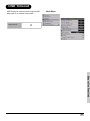
Reset
This resets all values in the “Option” menu to
the factory defaults.
Main Menu
Lamp Timer Reset
Easy to Use Functions
The projector keeps a record of the total time
the lamp has been in use. You should reset the
timer after you install a new lamp. The total
lamp usage time is shown in the Status Screen.
50
Main Menu
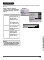
Status Screen
The Status screen displays information about the current input signal.
Main Menu
Factory reset
This resets all setting to the factory defaults.
The logo is shown for about 20 seconds, then
the projector is reset.
Main Menu
Easy to Use Functions
Screen display during Factory Reset
51
Easy to Use Functions
NOTES
52
Appendix
Appendix
53
Maintenance
Cleaning the projector
Unplug the power cord before cleaning the projector.
Avoid using benzene or thinner, as these can damage the finish on the cabinet and operation panel.
Do not use volatile agents, such as insecticides, on the projector.
Do not leave rubber or plastic objects in contact with the projector for long periods, as they may damage
the finish of the projector.
Wipe off dirt gently with a soft flannel cloth.
For hard-to-remove dirt, soak a cloth in a neutral detergent diluted with water, wring the cloth well and then
wipe the projector.
Strong cleaning detergents may discolor, warp or damage the coating on the projector. Make sure to test
on a small, inconspicuous area on the projector before using.
nt
rge
ete
al d
utr
Ne
Neutral detergent
diluted with water
Cleaning the lens
Use a commercially available blower or lens cleaning paper (for glasses and camera lenses) for cleaning
the lens. Do not use any liquid cleaning agents, as they may wear off the coating film on the surface of the
lens.
Cleaning
Paper
The surface of the lens is easily damaged, do not to scrape or hit the lens.
Appendix
Cleaning the exhaust and intake vents
Use a vacuum cleaner to clean dust from the exhaust vent and the intake vent.
54
Cleaning the Ventilative Holes
• This projector has ventilative holes to
ensure the optimal operating condition of
the projector.
• Periodically clean the ventilative hole by
vacuuming it off with a vacuum cleaner.
• The ventilative holes should be cleaned
every 100 hours of use. Clean the
ventilative holes more often when the
projector is used in dirty or smoky locations.
Side and Rear view
Bottom view
Ventilative holes
Ventilative holes
Cleaning the
Ventilative Holes
ENTER
1
Turn off the power and
disconnect the power cord.
STATUS
MENU
EXIT
ECO
INPUT
Press
on the projector or
on
the remote control to turn off the power.
Wait until the cooling fan stops.
2
Power button
Unplug the Power Cord.
Pr/Cr
Pb/Cb
Y
PC
DVI
Made in Taiwan
mp chassis cover while replacing the lamp.
xt to them until they have sufficiently cooled down.
nvironment.
3
Clean the dust off by placing the
cleaner hose on the intake and
exhaust ventilative holes.
Appendix
55
About the Lamp
The projector lamp has a life of 2000 hours. Maintain proper ventilation to keep the lamp operating
throughout its lifetime. Do not subject the projector to unnecessary vibration to ensure that the
lamp does not break.
It is recommended that the lamp (sold separately) be replaced after approximately 2,000 cumulative hours
of use or when you notice a significant deterioration in the picture and color quality. The number of hours
the lamp has been used can be checked with “Lamp Timer” in the “Options” menu on the menu screen.
For lamp replacement, please consult your nearest authorized service center or sealer.
The actual lamp service life may be less than 2000 hours depending on the environment in which the
projector is used.
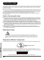
Caution Concerning the Lamp
This projector uses a pressurized mercury lamp. A loud sound may indicate lamp failure. Lamp failure is
caused by excessive shock, improper cooling, surface scratches or deterioration of the lamp due to usage.
The period of time up to failure largely varies depending on the individual lamp and/or the condition and
the frequency of use. It is important to note that failure can often result in the bulb cracking.
When the lamp replacement indicator and on-screen display icon are illuminated or are flashing, it is
recommended that the lamp be replaced immediately, even if the lamp appears to be operating normally.
If the lamp breaks glass particles may spread inside the lamp cage or gas contained in the lamp may be
vented into the room from the exhaust vent. As the gas in this lamp contains mercury, ventilate the room
well if the lamp breaks and avoid all exposure to the released gas. In case of exposure to the gas, consult
a doctor as soon as possible.
If the lamp breaks, there is also a possibility that glass particles may spread inside the projector.
If this happens, it is recommended you contact your nearest authorized dealer to remove the damaged
lamp and assure safe operation.
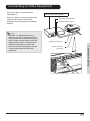
Replacing the Lamp
CAUTION! Do not remove the lamp unit immediately after operation of the projector. The
lamp will be hot and touching it may cause injury. Wait at least one hour after the power cord
is disconnected to allow the surface of the lamp unit to fully cool before removing the lamp
unit.
Temperature LED (Over Temperature)
The over temperature alarm LED on the control panel alerts you when the projector lamp becomes too hot.
ENTER
STATUS
MENU
EXIT
Appendix
ECO
Over Temperature Alarm
LED
INPUT
If the LED illuminates during operation, the lamp will shut off and the cooling fans will continue to run for
approximately two minutes. You should ensure that the airflow around the projector is sufficient, and that the
aire filters are not clogged to ensure that the projector has proer ventilation.
Over Temperature !
When the temperature LED lights up, a warning also appears on the screen.
56
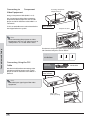
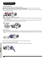
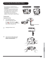
Removing and Installing the Lamp Unit
Follow these instructions to replace the lamp.
• Remove the lamp unit by the handle.
Do not to touch the glass surface of the lamp unit or the inside of the
projector.
• To avoid injuring yourself and damage to the lamp, carefully follow the steps below.
• Do not loosen other screws except for the lamp unit cover and lamp unit.
(Only the silver screws are loosened).
1. If the projector is running, press
on the projector or
turn off the power. Wait until the cooling fan stops.
on the remote control to
ENTER
STATUS
MENU
EXIT
ECO
INPUT
Warning!
Do not remove the lamp unit from the projector imme diately after use. The lamp will be very hot and may
cause injury.
2. Disconnect the power cord and wait at least an hour for the lamp to cool.
3. Remove the lamp unit cover.
• Loosen the user service screw that secures the lamp uni
t cover. Then open the cover in the direction of the
arrow.
Appendix
M4* 8.9 screws
57
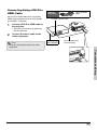
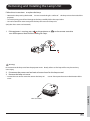
4. Remove the lamp unit.
• Loosen the securing screws from the lamp unit. Hold the lamp unit by the handle and pull it in the direction
of the arrow.
5. Insert the new lamp unit.
• Press the lamp unit firmly into the lamp unit compartment. Fasten the securing screws.
• Attach the lamp unit cover.
• Close the lamp unit cover in the direction of the arrow (to the close mark) on the side of the projector.
• Tighten the user service screw.
Info
• If the lamp unit and lamp cover are not correctly installed, the power will not turn on, even if the power cord
is connected to the projector.
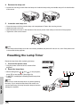
Resetting the Lamp Timer
Reset the lamp timer after replacing the lamp.
Pr/Cr
1. Connect the power cord.
• Plug the power cord into the AC socket of the
Pb/Cb
Y
PC
DVI
Made in Taiwan
mp chassis cover while replacing the lamp.
xt to them until they have sufficiently cooled down.
projector.
nvironment.
2. Reset the lamp timer.
• While holding down
,
and
on the projector,
ENTER
press
on the projector. (See page 50)
• “LAMP 0H” is displayed, indicating that the lamp timer
is reset.
ENTER
Info
Appendix
ENTER
Make sure to reset the lamp timer only when replacing
the lamp. If you reset the lamp timer and continue to
use the same lamp, this may cause the lamp to become
damaged or explode.
58
STATUS
MENU
EXIT
ECO
INPUT
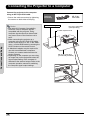
Connecting Pin Assignments
DVI-D port: 25 pin connector
• DVI Digital INPUT
24 23
~
18 17
8 7
~
~
21
Pin No.Signal
Pin No.Signal
1 T.M.D.S data 216 Hot plug detection
2 T.M.D.S data 2+
17 T.M.D.S data 0–
3 T.M.D.S data 2 shield 18 T.M.D.S data 0+
4 Not connected
19 T.M.D.S data 0 shield
5 Not connected
20 Not connected
6 DDC clock
21 Not connected
7 DDC data
22 T.M.D.S clock shield
8 Not connected
23 T.M.D.S clock+
9 T.M.D.S data 1–
24 T.M.D.S clock–
10 T.M.D.S data 1+
C1 Ground
11 T.M.D.S data 1 shield
12 Not connected
13 Not connected
14 +5V power from
graphic card.
15 Ground
C1
16
9
RS-232C Port: 9-pin D-sub Female connector of the DIN-D-sub RS-232Cvt cable pin connector
54321
9876
Pin No. Signal
1
2
3
4
5
6
7
8
9
Name
SD Send Data
RD Receive Data
SG Signal Ground
I/O
Input
Output
Reference
Not connected
Connected to internal circuit
Connected to internal circuit
Not connected
Connected to internal circuit
Not connected
Not connected
Not connected
Not connected
Appendix
59
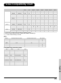
Computer Compatibility Chart
Computer
• Multiple signal support
Horizontal Frequency: 25–75 kHz, Vertical Frequency: 50–85 Hz, Pixel Clock: 25–108 MHz
• Compatible with sync on green and composite sync signals
• XGA compatible with advanced intelligent compression
The following is a list of modes that conform to VESA. However, this projector supports
other signals that are not VESA standards.
PC/
MAC/
WS
Horizontal
Vertical
VESA
DVI
Frequency Frequency Standard
Support
(kHz)
(kHz)
Resolution
640 x 350
PC
VGA
640 x 480
Resolution
Horizontal
Frequency
(kHz)
31.5
70
31.5
60
37.9
72
3
37.5
75
3
43.3
85
3
31.5
60
720 × 576
31.3
50
DVI 1280 × 720
1980 × 1080i
45
60
37.5
50
33.8
60
28.1
50
Resolution
SVGA
800 x 600
3
PC
Vertical
Stan- DVI
Frequency VESA
dard
Support
(kHz)
720 × 480
PC/
MAC/
WS
3
Display
Upscale
MAC
13”
XGA
1024 x 768
VGA
640 x 480
Horizontal
Vertical
VESA
DVI
Frequency Frequency Standard
Support
(kHz)
(kHz)
35.1
56
37.9
60
48.1
72
46.9
75
48.4
60
56.5
70
60.0
75
68.7
85
34.9
67
MAC SVGA
16”
832 x 624
49.6
75
MAC
19”
1024 x 768
48.4
60
XGA
3
3
3
3
3
Note
• This projector may not be able to display images from notebook computers in simultaneous (CRT/LCD)
Appendix
mode. Should this occur, turn off the LCD display on the notebook computer and output the display data
in “CRT only” mode. Details on how to change display modes can be found in your notebook computer’s
operation manual.
• When this projector receives 640 × 350 VESA format VGA signals, “640 × 400” appears on the screen.
• When projecting video images of an interlace video signal with the projector, the intended image may
not be projected depending on the video signal when using the RBG input. In such cases, use the
component input, S-video input or video input.
60
Video Compatibility Chart
Resolution
H-Freq
(kHz)
V-Freq
(Hz)
Comp1
Support
Comp2
Support
S-Video ComposVGA
Support ite Support Support
NTSC
640x480i
15.73
59.94/60
3
3
3
3
PAL
768x576i
15.63
50
3
3
3
3
SECAM
768x576i
15.63
50
3
3
3
3
NTSC-4.43
U
U
U
U
PAL-M
U
U
U
U
PAL-N
U
U
U
U
NTSC-J
U
U
U
U
PAL-60
U
U
U
U
SD Video
DVI
Support
NTSC-50
480P
720x480P
31.5
59.94/60
3
3
3
3
576P
720x576P
31.3
50
3
3
3
3
1080i/50
1920x1080i
33.8
50
3
3
3
3
1080i/60
1920x1080i
28.1
59.94/60
3
3
3
3
720P/50
1280x720P
37.5
50
3
3
3
3
720P/60
1280x720P
45.0
59.94/60
3
3
3
3
720P/48
1280x720P
48
720P/75
1280x720P
75
ED TV
HD TV
HTPC
1. Component 1/2 support signal formats are Y/Pb/Pr, Y/Cb/Cr
2. VGA port support signal formats are RGsyncB, RGBHV or RGBCsysc
3. “U” means manual setting is needed
DTV
Signal
Horizontal Frequency (kHz)
Vertical Frequency (Hz)
DVI Support
480P
31.5
60
3
576P
31.3
50
3
720P
45.0
60
3
720P
37.5
50
3
1080I
33.8
60
3
1080I
28.1
50
3
IR Remote Key Discrete Codes
Key
Code
Key
Code
IR POWER
0x00
IR_Aspect
0x0c
IR MENU
0x01
IR_PowerOff
0x0d
IR UP
0x02
IR_Standard
0x0e
IR DOWN
0x03
IR_Letterbox
0x0f
IR LEFT
0x04
IR_Anamorphic
0x10
IR RIGHT
0x05
IR_PixelToPixel
0x11
IR ENTER
0x06
IR_S_Video
0x12
IR_Exit
0x07
IR_Composite
0x13
IR_Source1 0x08
IR_Component1
0x14
IR_Source2 0x09
IR_Component2
0x15
IR_Source3 0x0a
IR_DVI
0x16
IR_Source4 0x0b
IR_PC
0x17
Appendix
61
Troubleshooting
Problem
Check
Projector power cord is not plugged into the wall outlet.
Remote control batteries have run out.
Projector does not start
The selected input mode is wrong.
Cables may be incorrectly connected to the rear panel of the projector.
Power to the external connected device is off.
The video signal format of the video equipment is not set correctly.
No picture
Picture adjustments are incorrectly set.
Color is faded
Focus is incorrectly set.
The projection distance exceeds the focus range.
Picture is blurred
(PC input only)
Try "Auto tune".
Adjust the "Clock" setting.
Adjust the "Phase” setting.
Picture noise appears.
Appendix
Change the input signal type of the video equipment.
Picture is green on
INPUT1 or 2 COMPONENT
62
Picture adjustments are incorrectly set.
Picture is dark or
bright and whitish
Picture adjustments are incorrectly set.
Picture is too bright
and whitish
Appendix
63
$IMENSIONS
5NITSINCHESMM
5HDU9LHZ
9,'(2
69,'(2
3U&U
3E&E
3U&U
<
3E&E
<
3&
'9,
56
:$51,1*
0DGHLQ7DLZDQ
v 'RQRWGLVDVVHPEOHDQ\FRPSRQHQWVH[FHSWWKHODPSFKDVVLVFRYHUZKLOHUHSODFLQJWKHODPS
v 'RQRWWRXFKYHQWLODWLRQVORWVODPSDQGREMHFWVQH[WWRWKHPXQWLOWKH\KDYHVXIILFLHQWO\FRROHGGRZQ
v 1HYHULQVHUWDQ\REMHFWVWKURXJKYHQWLODWLRQKROHV
v 'RQRWXVHWKLVXQLWQHDUZDWHURULQDUDLQ\PRLVWHQYLURQPHQW
6LGH9LHZ
6LGH9LHZ
,1387
LQFK
(&2
(;,7
LQFK
PP
0(18
67$786
PP
7RS9LHZ
(17(5
/(166+,)7
/(166+,)7
+
9
=RRP
)RFXV
LQFK
PP
LQFK
PP
LQFK
PP
PP
LQFK
LQFK
PP
LQFK
)URQW9LHZ
PP
LQFK
PP
LQFK
LQFK
LQFK
PP
LQFK
PP
! PPE N DIX
%RWWRP9LHZ
PP
LQFK
PP
PP
LQFK
PP
LQFK
LQFK
PP
PP