1
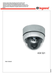
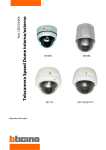
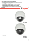
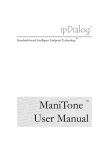
3.6-44.3mm 12X motorized day/night dome colour camera
4 305 21
3.5-94.5 mm 27X motorized day/night dome colour camera
4 305 22
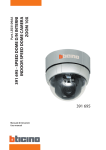
3.6-44.3mm 12X weatherproof motorized day/night dome colour camera
4 305 23
3.5-94.5 mm 27X weatherproof motorized day/night dome colour camera
4 305 24
3.5-129.5 mm 37X weatherproof motorized day/night dome colour camera
4 305 25
4 305 21
4 305 22
4 305 23
4 305 24/25
LE03668AB
USER MANUAL
Important Safety Guide
Read, heed and follow all the Instructions
Read all the safety and operating instructions before using the product.
Keep this manual
Keep this manual for reference in future.
Attachments / Accessories
Use only the attachments or accessories specified by the manufacturer.
Installation
Do not install near any heat resources such as radiators, heat registers, stoves, or other appratus including amplifiers that
product heat. Improperly installed product may fall, cause serious injury to a child or adult and damage the product.
Do not block any ventilation holes or openings. Install in accordance with the manufacturer’s instructions.
Use only with the cart, stand, tripod, bracket, mounting devices, or table specified by the manufacturer.
Installation should be done only by qualified personnel and conform to all the instructions by the manufacturer.
Refer all servicing to qualified service personnel.
Unless the product is specifically marked as IP67, more than IP67 or confirmed by the manufacturer, it is designed for
indoor use only and it must not be installed where exposed to rain and moisture.
Do not load on the product.
Use stainless steel hardware to fasten the mount.
To prevent damage from water leakage when installing a mount outdoors on a roof or wall, apply sealant properly
around holes.
These servicing instructions are for use by qualified service personnel only. To reduce the risk of electric shock, do not
perform any servicing other that contained in the operation instructions unless you are qualified to do so.
Use only replacement parts specified by the manufacturer.
Power source
This product should be operated only from the type of the power source indicated on the marking label.
2
CAUTION
Operating
Before using, make sure that the power supply and others are properly installed.
While operating, if any abnormal condition or malfunction is observed, stop using the product immediately and then
contact your local dealer.
Handling
Do not disassemble or tamper with the parts inside the product.
Do not drop or subject the product to shock and vibration as this can damage the product.
Care must be taken when you clean the clear dome cover. Especially, scratch and dust will ruin the quality of the product.
Installation and Storage
Do not install the product in areas of extreme temperature, which exceed the allowable range.
Avoid installing in humid or dusty places.
Avoid installing in places where radiation is present.
Avoid installing in places where there are strong magnetic fields and electric signals.
Avoid installing in places where the product would be subject to strong vibrations.
3
Table of contents
Important Safety Guide ...............................................................................................................................2
CAUTION ........................................................................................................................................................3
1
2
3
4
INTRODUCTION......................................................................................................................................6
1.1
MODEL CODE............................................................................................................................................... 6
1.2
FEATURES.................................................................................................................................................... 6
1.3
Package Component................................................................................................................................... 9
1.4
Main Part Description ............................................................................................................................... 11
INSTALLATION.....................................................................................................................................15
2.1
DIP Switch Setup ....................................................................................................................................... 15
2.2
In-Ceiling Mount Installation (4 305 21 Model)..................................................................................... 19
2.3
Installation with Surface Mount Bracket (4 305 21 Model) .............................................................. 20
2.4
Direct Installation on the Ceiling (4 305 22 model) ............................................................................. 21
2.5
Installation using In-Ceiling Mount Bracket (4 305 22 model) ......................................................... 22
2.6
Installation using Ceiling Mount Bracket (4 305 22 model)............................................................... 23
2.7
Installation using Wall Mount Bracket (4 305 22 model).................................................................... 24
2.8
Installation with Ceiling Mount Bracket (4 305 23/4 305 24/4 305 25 Models)................................ 25
2.9
Installation with Wall Mount Bracket (4 305 23/4 305 24/4 305 25 Models) .................................... 26
2.10
Wiring and Cabling (4 305 21/4 305 23/4 305 24/4 305 25) ................................................................. 27
Operation...............................................................................................................................................32
3.1
Check Points before Operation .............................................................................................................. 32
3.2
Check Points for Preset and Pattern Function before Operation .................................................... 32
3.3
OSD Menu ................................................................................................................................................... 33
3.4
Reserved Presets (Hot Keys) .................................................................................................................. 33
3.5
Preset........................................................................................................................................................... 34
3.6
Swing ........................................................................................................................................................... 34
3.7
Pattern ......................................................................................................................................................... 35
3.8
Group........................................................................................................................................................... 36
3.9
Other Functions......................................................................................................................................... 37
3.10
OSD Display ............................................................................................................................................... 38
OSD MENU ............................................................................................................................................39
4.1
Quick Programming Guide ...................................................................................................................... 39
4.2
Main Menu................................................................................................................................................... 39
4.3
Display setup.............................................................................................................................................. 40
4.4
Privacy Zone Mask Setup ........................................................................................................................ 41
4
5
4.5
Camera Setup (Dome Camera Setup Menu)......................................................................................... 43
4.6
Motion Setup .............................................................................................................................................. 47
4.7
Preset Setup ............................................................................................................................................... 50
4.8
Swing Setup ............................................................................................................................................... 53
4.9
Pattern Setup.............................................................................................................................................. 54
4.10
Group Setup ............................................................................................................................................... 55
4.11
System Initialization.................................................................................................................................. 58
Specifications .......................................................................................................................................60
5.1
Dimension................................................................................................................................................... 65
5
1 INTRODUCTION
1.1
MODEL CODE
Ref.
4 305 21
Serie
Mini plastic
small
4 305 22
4 305 23
Mini
Aluminium
with
fan/heater
Mini Aluminium
with fan/heater
4 305 25
Aluminium
with
fan/heater
YES
PAL
Video signal
Wall mount
bracket
NO
YES
Rated power :
1.2
Aluminium with
fan/heater
NO
Outdoor serie
In / Out Trigger
alarm
4 305 24
12 VDC
3 In / 1 Out
4 In / 2 Out
3 In / 1 Out
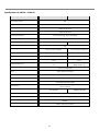
FEATURES
Powerful Zoom Camera & Setup Options
4 305 21
4 305 22
4 305 23
4 305 24
4 305 24
Optical Zoom
12
x27
x12
x27
x37
Digital Zoom
12
x12
x12
x12
x12
Max. zoom
magnification
144
324
x144
x324
x444
High light compensation
NO
NO
NO
YES
YES
Privacy Masks
8
8
8
8
8
YES
Day & Night
NO
WDR
YES
Focus Mode
Auto-Focus, Manual Focus, Semi-Auto Focus
OSD Menu
YES
Sensor
¼”super HAD
color CCD
¼” super HAD
color CCD
¼” super HAD
color CCD
¼” super HAD color CCD
Powerful Pan/Tilt Functions
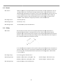
MAX. 360/sec High Speed Pan/Tilt Motion
With the Vector Drive Technology, Pan/Tilt motions are accomplished along the shortest path. As a result, the time
to target view is remarkably short and the video on the monitor is very natural in monitoring.
6
With the Micro-Stepping Control Technology, the video looks very natural at high zoom magnification during a jog
operation on a controller since the camera can be controlled by 0.05/sec. Hence it is very easy to make the camera
focus on desired target views at high zoom magnification. Additionally it is easy to make the camera focus on
desired positions with zoom-proportional pan/tilt movement.
Preset, Pattern, Swing, Group, Privacy Mask and More…
MAX. 127 Presets are programmable and each preset can have its own parameter values independently from the
other presets.
For an example, refer to the below table.
Preset No.
White
Balance
Auto Exposure •••
Label
Preset 1
Case A
Case 3
“ENTRANCE”
Preset 2
Case C
Case 5
“WAREHOUS
E”
Preset 3
Case V
Case 2
“OFFICE”
Remarks
•••
Preset 95
Reserved for OSD Menu
•••
Preset 128 Case K
Case 9
“TERRACE”
MAX. 4 Patterns are programmable. This function is that the camera memorizes the path (mostly curve path) by the
joystick of the controller and revives the trajectory operated by the joystick as closely as possible.
MAX. 8 sets of Group are programmable. This function is that the camera memorizes the combination of Presets,
Pattern and/or Swings sequently and runs Presets, Pattern and/or Swings repetitively. A Group can be combined
upto 20 functions with any of Preset/Pattern/Swing.
8 Privacy Masks are programmable, not to intrude on any other’s privacy :
PTZ (Pan/Tilt/Zoom) Control
With the RS-485 communication connection, MAX. 255 units of cameras can be connected to a single controller.
Pelco-D or Pelco-P protocols can be selected as a control protocol in the current firmware version.
OSD (On Screen Display) Menu
OSD menu is provided to display the status of camera and to configure the functions interactively.
The information such as Camera ID, Pan/Tilt Angle, Direction, Alarm Input and Preset is displayed on screen.
Alarm In/Out Function
4 305 22 : 4 alarm sensor inputs and 2 alarm output relays
4 305 21/4 305 23/4 305 24/4 305 25 : 3 alarm sensor inputs and 1 alarm sensor outputs
Alarm sensor input is decoupled with photo-couplers to avoid external electric noise and shock perfectly.
7
Both of N.O.(Normal Open) sensors and N.C.(Normal Close) sensors can be used and the signal range of the sensor
input is from DC 5.0V to 12.0V for various applications.
The camera can be set to move to a Preset position or to run functions such as Pattern, Swing and Group when
there are external sensor activations. Also “Post Alarm” function is possible, which is supposed to activate after
user-defined time period and sequentially in succession to the action by external sensor activations.
Reserved Presets (Hot Keys)
Most camera setup options can be set up easily and directly with the reserved presets (Hot Keys), without entering
into OSD menu. For more information, refer to “Reserved Presets (Hot Keys)” in this manual.
Perfect Outdoor Environment Compatibility and Easy Installation
4 305 23/4 305 24/4 305 25 : The fans and heaters are built-in in the camera for cold and hot temperature
environment. Also idealistic mechanical design protects the camera from water and dust. (IP67 when installed
properly with wall mount bracket only)
8
1.3
Package Component
(4 305 21 Model) Product & Accessories
Main Body & Surface Mount Bracket
Default Accessories
[Main Cable, Calblock, Screws : Tapping M4
M416, Tapping M425,
Machine M36,
6, Machine M3
M38]
I/O Cable
(4 305 22 Model) Product & Accessories
Main Body / Terminal Cover
Dome Cover
Screws
Optional brackets
In-Ceiling Mount Bracket
Ceiling Mount Bracket
Corner bracket
Wall mount bracket
4 305 96
4 305 97
4 305 98
4 305 94
9
(4 305 23/4 305 24/4 305 25 Models)
s) Product & Accessories
Default Accessories
Main Body & Surface Mount Bracket
[Main Cable, Wrench]
Wall Mount Bracket
Accessories for The Models with Alarm In/Out
Function [I/O Cable]
[Screws : Machine M515,
15, Hex Lag #14
#1450]
Optional Brackets
Corner bracket 4 305
5 98
Ceiling Mount Bracket 4 305 95
Pole bracket 4 305 99
10
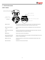
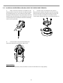
1.4
Main Part Description
(4 305 21 Model)
Surface Mount Bracket
Mounting Screw Hole
Main Connector
Sensor I/P Port
Dome Cover
Assembly Stud
Dome Cover Lock-up Screw
DIP Switch
Dome Cover
Dome Cover
Do not detach the protection vinyl from the dome cover before finishing all the
installation process to protect the dome cover from scratches or dust.
Dome Cover Lock-up
Used to lock up the dome cover after assembling the dome cover with the main
body.
Screw
Dome Cover Assembly
Stud
Used to line up the stud on the main body and the stud on the dome cover when
assembling the dome cover with the main body.
DIP Switch
Used to set up camera IDs and protocols.
Surface Mount Bracket
Used for surface mount type, wall mount type and ceiling mount type. They are not
used for in-ceiling mount type.
& Mounting Screw Hole
Main Connector
Used for the power wire, the video cable and the RS-485 communication cable
connection.
Sensor I/O Port
Used for the sensor in/out connection.
11
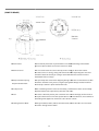
(4 305 22 Model)
Dome Cover
Do not detach protection vinyl from dome cover before finishing all installation
process to protect dome cover from scratches
es or dust
Terminal Cover
This is used to install the camera directly on the ceiling or attach to the other
brackets such as in-ceiling,
in ceiling, ceiling and wall mount. After separating this cover first
and then attach this directly to ceiling or to the other bracket. Camera must be
assembled at the last stage.
Drop Prevention Spring
This part keeps the camera from dropping during installation and maintenance. After
install the Terminal Cover, please, hang the spring to the drop prevention hook of
main body as shown in picture for further tasks.
Drop Prevention Hook
Lockup Screw
After assembling Terminal Cover to main body, screw Terminal Cover to main body
to protect them from separation by vibration and so on.
Fuse
If the fuse is burnt to protect your came from over-current
over current damage, the fuse have to
be replace with new one. The fuse specification is 250V 2A. However, we recommend
consulting with supplier to remove the cause of over
over-current.
Cabling Terminal Block
During installation, Power, Video, Communication,
C
, Alarm I/O cables are connected
on to this cabling terminal block.
12
Terminal Cover Disassembling
① Remove the Lockup Screw as shown bellow.
②
Turn main body on its axis in
CCW(Counter-clockwise) direction and separate
it from Terminal Cover.
Terminal Cover Assembling
①
Check if the summit of the Plate Spring is
located at the arrow mark as shown in the dotted
circle.
② Check the 2 mold line for assembly before
starting assembly. Line up the mold lines as
shown in the dotted circle and turn main body
on its axis in CW(Clockwise) direction and
assemble main body to Terminal Cover. After
assembling them, screw main body to Terminal
Cover to protect them from separation by
vibration and so on.
13
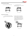
(4 305 23 Model)
Mo u n t in g Scr ew Ho le
Mo u n t in g Ho o k
DIP Switch
Main Co n n ect o r
Sen s o r I/ O Po r t
Do m e Co ver
Main Body / Terminal Cover
Dome Cover
Do not detach the protection vinyl from the dome cover before finishing all
the installation process to protect the dome cover from scratches or dust.
DIP Switch
Used to set up camera IDs and protocols.
Mounting Hook
Used to assemble the main body with wall mount bracket or ceiling mount
bracket. Insert the mounting hooks into the holes on the surface of the
main body and turn the main body.
Mounting Screw Hole
Used to assemble the main body with a bracket with screws.
Main Connector
Used for the power wire, the video cable and the RS-485 communication
cable connection.
Sensor I/O Port
Used for the sensor in/out connection.
14
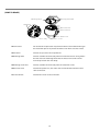
2 INSTALLATION
2.1
DIP Switch Setup
(4 305 21/4 305 23/4 305 24/4
4 305 25 models)
Before installing the camera, set up the DIP switch to configure the camera ID and the communication protocol.
ON
ON
1
2
3
4
5
6
7
8
(4 305 22 model)
Before you install the camera, you should set the DIP switches to configure the camera ID, communication protocol. Do not use
the ISP connector. (Authorized person only !)
15
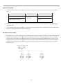
Camera ID Setup
ID numbers of cameras are set up with binary numbers. See the examples shown below.
Pin
1
2
3
4
5
6
7
8
Binary Value
1
2
4
8
16
32
64
128
Ex : ID=5
on
off
on
off
off
off
off
off
Ex : ID=10
off
on
off
on
off
off
off
off
The camera ID range is “1~255”. Camera ID must not be “0”! Factory default of Camera ID is 1.
The factory default of the camera ID is “1”.
Match the camera ID with the Cam ID setting of your DVR or Controller to control the camera.
If you are connecting a single camera to a controller, terminate the camera. When connecting more than one camera to a
single controller, terminate the last camera on the communication line. The last camera means the camera farthest in
cable length from the controller.
Note that the total length of the communication cable between a controller and the camera(s) on the sam
same
communication line must be less than 1.2Km
Communication Protocol Setup
Select the appropriate Protocol with DIP switch combination.
Switch State
Protocol/Baud rate
P0
P1
P2
(Pin 1)
(Pin 2)
(Pin 3)
OFF
OFF
OFF
PELCO-D,
D, 2400 bps
ON
OFF
OFF
PELCO-D,
D, 9600 bps
OFF
ON
OFF
PELCO-P,
P, 4800 bps
ON
ON
OFF
PELCO-P,
P, 9600 bps
Otherwise
Reserved
If you want to control using DVR or P/T controller, their protocol must be identical to camera. Otherwise, you can not
control the camera.
If you changed camera protocol by changing DIP S/W, the change will be effective after you reboot the camera.
Factory default of protocol is “Pelco-D,
D, 2400 bps”.
bps
16
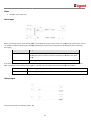
Terminal resistor Setup
Terminal resistor is used if your system is one of following two cases.
Case1: Control cable between camera and controller is relatively very long (1:1 connection)
If communication cable is very long, the electrical signal will bound in the terminal point. This reflected signal cause distortion of
original signal. Accordingly,
dingly, the camera can be out of control. In this case, the terminal resistor of both sides i.e. camera and
controller must be set to ‘ON’ state.
Case2: Multiple cameras are controlled at the same time
Due to similar reasons with case 1, the terminal resisters
sters of controller and the last camera must be set to ‘ON’ state. Last camera
means decided by cable length. Do not turn on the terminal resistor of all cameras.
17
Sensor Type Setup
If you want to use Alarm Input, the types of sensor must be selected. The sensor types are Normal Open and Normal.
Normal Open
Output Voltage is high state when sensor is activated.
Normal Close
Output Voltage is high state when sensor is not activated.
Pin No
ST1 (Pin 4)
ST2 (Pin 5)
ST3 (Pin 6)
ST4 (Pin 7)
Switch State
Sensor Type
ON
Sensor 1 : Normal Close Type
OFF
Sensor 1 : Normal Open Type
ON
Sensor 2 : Normal Close Type
OFF
Sensor 2 : Normal Open Type
ON
Sensor 3 : Normal Close Type
OFF
Sensor 3 : Normal Open Type
ON
Sensor 4 : Normal Close Type
OFF
Sensor 4 : Normal Open Type
If sensor type is not selected properly, the alarm can be activated reversely.
18
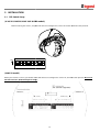
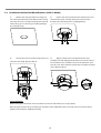
2.2
In-Ceiling Mount Installation (4 305 21 Model)
①
Remove the ceiling tile from the ceiling and cut a
hole whose diameter is 110mm on the ceiling tile to pass
the wires and cables through to the upside of ceiling.
②
Connect the wiring and cabling and attach the
camera to the ceiling tile. (Tapping M416).
③
Align the dome cover stud with the dome cover
assembly stud and slightly push the dome cover to the
ceiling tile.
④
Turn the dome cover clockwise and screw on the
dome cover lock-up screw. Then remove the protection
vinyl from the dome cover. (Machine M36)
Important Notice
Before starting the installation, make sure that the Camera ID and Protocol are set up properly.
19
2.3
Installation with Surface Mount Bracket (4 305 21 Model)
①
Remove the ceiling tile from the ceiling and
cut a hole whose diameter is 30~40mm on the ceiling
tile to pass the wires and cables through to the upside
of the ceiling. (In case of wiring and cabling through
the ceiling tile only)
②
Prepare the surface mount bracket. Pull the wires and
cables for the system as below. Attach the surface mount
bracket to the mounting surface. (Tapping M425)
③
④
Align the dome cover stud with the dome cover
assembly stud and slightly push the dome cover to the ceiling.
Turn the dome cover clockwise and screw on the dome cover
lock-up screw. Then remove the protection vinyl from the dome
cover. (Machine M36)
Connect the wires and cables to the ports and
install the main body. (Machine M38)
Important Notice
Before starting the installation, make sure that the Camera ID and Protocol are set up properly.
When the pipe hole for wiring and cabling on side of the Surface Mount Bracket is not used, make sure that the hole is
properly sealed with the supplied Hole Plug.
20
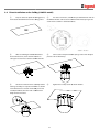
2.4
Direct Installation on the Ceiling (4
( 305 22 model)
①
To pass cables to upside of ceiling, please,
make about 50~60mm hole on the ceiling panel.
②
For cable connection, remove the pre
pre-defined hole mark on
the Rubber Gasket and locate the summit of the Plate Spring at the
arrow mark as shown in the dotted circle.
③
After assembling the Rubber Gasket to
the Terminal Cover, install Terminal Cover on
ceiling tex and connect cables to terminal blocks.
④
Connect the “Drop Prevention
evention Spring
Spring” to the main body to
prevent camera from drop.
⑤
Check the 2 mold line for assembly before
starting assembly. Line up the mold lines as shown
in the dotted circle and turn main body on its axis
in CW(Clock-Wise)
Wise) direction and assemble main
body to Terminal Cover.
⑥
21
Tighten the Lockup Screw as shown bellow.
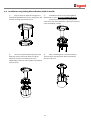
2.5
Installation using In-Ceiling
Ceiling Mount Bracket (4 305 22 model)
①
Cut the panel of ceiling as shown bellow.
③
Locate the summit of the plate spring at the
arrow mark as shown in the dotted circle.
②
Assemble Terminal Cover of camera to the
In-Ceiling Mount Bracket as shown bellow.
④ Assemble main body to Terminal Cover and
insert the assembly into ceiling tex.
Holes are to be used to sustain the device.
⑤ Screw camera to ceiling tex with 3 screws tightly.
⑥
Assemble Deco. Ring with camera and turn
Deco. Ring on its axis in CW(Clockwise) direction.
22
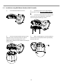
2.6
Installation using Ceiling Mount Bracket (4 305 22 model)
①
To pass cables to upside of ceiling, please
make about 50~60mm hole on the ceiling panel and
attach the Ceiling mount bracket on it.
②
Assemble Terminal Cover to Ceiling Mount
Bracket with 3 screws. (Do not use Rubber Gasket !)
③
Connect “Drop Prevention Spring” to main
body to prevent camera from drop. Line up the
mold lines and turn main body on its axis in
CW(Clockwise) direction and assemble main body to
Terminal Cover.
④
After assembling them, screw main body to
Terminal Cover to protect them from separation by
vibration and so on.
Locate the summit of the Plate Spring at the
arrow mark. (For more information, refer to the “Terminal
Cover Assembling” section)
23
2.7
Installation using Wall Mount Bracket (4 305 22 model)
①
Install Wall Mount Bracket on wall.
②
Assemble Terminal Cover to Wall Mount
Bracket with 3 screws. (Do not use Rubber Gasket
!)
Locate the summit of the Plate Spring at the
arrow mark. (For more information, refer to the
“Terminal Cover Assembling” section)
③
Connect “Drop Prevention Spring” to main
body to prevent camera from drop. Line up the
mold lines and turn main body on its axis in
CW(Clockwise) direction and assemble main body to
Terminal Cover.
④
After assembling them, screw main body to
Terminal Cover to protect them from separation by
vibration and so on.
24
2.8
Installation with Ceiling Mount Bracket (4 305 23/4 305 24/4 305 25 Models)
①
Remove the ceiling tile from the ceiling and cut a
hole whose diameter is 30~40mm on the ceiling tile to pass
the wire(s) and cable(s) through to the upside of the
ceiling. (In case of the wiring and cabling through the
mounting surface only) Then prepare the ceiling mount
bracket. Pull the wire(s) for the system as below. (Anchor
Bolt 3/8"70)
②
Pull the wire(s) and cable(s) for the system as
below. Wire the cable(s) to the ports. Insert the mounting
hooks into the holes on the surface of the main body and
turn the main body. Assemble the main both with the
camera mount adaptor with the 3 screws. (Machine M515)
③
Screw the dome cover to the main body and
remove the protection vinyl from the dome cover.
Important Notice
Before starting the installation, make sure that the Camera ID and Protocol are set up properly.
To adjust the installation height from the mounting surface, the pipe and coupler should be needed between the surface
mount part of the ceiling mount bracket and the camera mount part of the ceiling mount bracket. Note that they are not
supplied by the manufacturer.
25
2.9
Installation with Wall Mount Bracket (4 305 23/4 305 24/4 305 25 Models)
①
Make a hole whose diameter is 30~40mm on the
mounting surface to pass the wire(s) and cable(s) through
the mounting surface. (In case of the wiring and cabling
through the mounting surface only) Then prepare the wall
mount bracket. Pull the wire(s) and cable(s) for the system
as below. Attach the wall mount bracket to the mounting
surface. (Hex Lag #1450)
②
Pull the wire(s) and cable(s) for the system as
below. Wire the cable(s) to the ports. Insert the mounting
hooks into the holes on the surface of the main body and
turn the main body. Assemble the main both with the
camera mount adaptor with the 3 screws. (Machine M515)
③
Screw the dome cover to the main body and
remove the protection vinyl from the dome cover.
Important Notice
Before starting the installation, make sure that the Camera ID and Protocol are set up properly.
26
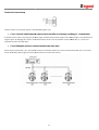
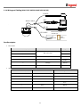
2.10 Wiring and Cabling (4 305 21/4 305 23/4 305 24/4 305 25)
POWER
BNC
MAIN CABLE
MONITOR
.
RS-485
I/O CABLE
CONTROLLER / DVR
SENSOR I/O
IR
SENSOR
DOOR
SWITCH
Port Description
Main Cable
Port Pin Number (RJ45)
Connector / Wire Color
1
Video +
BNC Connector
2,4
Signal
Video
5
Red
RS-485 +
3
Yellow
RS-485
7
Orange
Power +
6,8
White
Power
I/O Cable
Port Pin Number (RJ25)
Wire Color
Signal
1
Blue
IN COM +
2
Yellow
IN 1
3
Green
IN 2
4
Red
IN 3
5
Black
OUT A
6
White
OUT B
27
Power Description
Carefully check the voltage and current capacity of the rated power. The rated power is indicated in the back of main
unit.
Model
Input Voltage Range
4 305 21
Current Consumption
0.8 A
DC 11V ~ 15V
4 305 23/4 305 24/4 305 25
2.5 A
For the DC input models, be careful with the polarity of DC power. The system should be permanentally damaged by
wrong DC input.
In case that the length of the power wire is very long, there may be voltage drop and the syatem may not work properly.
Make the length of the power wire as short as possible.
RS-485 Communication
For PTZ control, connect the cable(s) to your keyboard or DVR. To connect multiple cameras to a single controller, RS
RS-485
communication should be connected in parallel as shown below. If you are connecting a single camera to a controller,
terminate the camera.
era. When connecting more than one camera to a single controller, terminate the last camera on the
communication line. The last camera means the camera farthest in cable length from the controller. Note that the total
length of the communication cable between
between a controller and the camera(s) on the same communication line must be
less than 1.2Km.
28
Video
Use BNC coaxial cable only.
Alarm Input
Before connecting sensors, check driving voltages and output signal types of the sensors. Since output signal types of the sensors
are divided into Open Collector type and Voltage Output type in general, the wiring must be done properly after considering
those types.
Signal
Description
IN COM+
The electric power source to drive input circuit. Connect the (+) wire of
electric power source to drive the Sensors to this port as shown in the above
circuit.
IN1 -, IN2 -, IN3 -
Connect the outputs of sensors to each port as shown in the above circuit.
If you want to use Alarm Input, the types of sensors must be selected in OSD menu. The
he sensor types are divided into Normal
Open and Normal Close. If wrong sensor types are selected, alarms should be activated reversely to sensor inputs.
Normal Open
Output
ut Voltage is high state when sensor is activated
Normal Close
Output Voltage is high state when sensor is not activated
Relay Output
The maximum loads are as follows:
s: 24 VDC ; 1A.
29
Wiring and Cabling (4 305 22 model)
Power Connection
Please, check the voltage and current capacity of rated power carefully. Rated power is indicated in the back of main unit.
Input Voltage Range
Current Consumption
11-15 VDC
0.75 A
Video Connection
Connect with BNC coaxial cable.
30
Alarm I/O Connection
Sensor Input
Before connecting sensors, check driving voltage and output signal type of the sensor. Since output signal types of
the sensors are divided into Open Collector and Voltage Output type in general, the cabling must be done properly
after considering these typed.
ped. Also, the sensor type, i.e. “Normal Open” or “Normal
Normal Close
Close” in Dip switch in main body
of camera must be set properly.
Signal
Description
IN COM+
Connect (+) cable of electric power source for Sensors to this port as
shown in the circuit above.
IN1, IN2, IN3, In4
Connect output of sensors for each port as shown in the circuit above.
Relay Output
Maximum allowable electrical load of relay is shown bellow table.
Drive Power
DC Power
AC 110V Power
Max. Load
DC 28V, 3A
AC110V, 3A
31
3 Operation
3.1
Check Points before Operation
Before turning on the system, check if the wire(s) and cable(s) are connected properly.
Check if the camera ID on the controller is properly selected. The camera ID must be identical to that of the target
camera. The camera ID can be checked by reading the DIP switch of the camera or on OSD.
If your controller supports multi-protocols, the protocol must be changed to match to that of the camera.
Adjust the DIP switch after turning off the camera. If you changed the camera protocol by changing the DIP S/W, the
change will be effective after you reboot the camera.
Since the operation method can be different by controllers, refer to your controller manual if the camera can not be
controlled properly. The operation of this manual is based on the standard Pelco® Controller.
3.2
Check Points for Preset and Pattern Function before Operation
Check fully how to operate preset function and pattern function with your controller or DVR in advance to operate the
camera functions when using a controller or a DVR.
Refer to the following table when using standard Pelco® protocol controllers.
< Go Preset >
Input [Preset Number] and press [Preset] button shortly.
< Set Preset >
Input [Preset Number] and keep pressing [Preset] button for more than 2 seconds.
< Run Pattern >
Input [Pattern Number] and press [Pattern] button shortly.
< Set Pattern >
Input [Pattern Number] and keep pressing [Pattern] button for more than 2 seconds.
If your controller or DVR has no pattern button or function, use the Hot Keys with preset numbers. For more information,
refer to “Reserved Presets(Hot Keys)” in this manual.
32
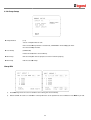
3.3
3.4
OSD Menu
Function
With OSD menu, the system can be properly configured for each application.
Entering into OSD
Go Preset [95]
Reserved Presets (Hot Keys)
Description
Some Preset numbers are reserved to change some parameters without entering into OSD menu.
Hot Keys
Go Preset [95]
: Entering into OSD menu
Go Preset [131~134]
: Running Pattern Function 1 ~ 4
Go Preset [141~148]
: Running Swing Function 1 ~ 8
Go Preset [151~158]
: Running Group Function 1 ~ 8
Go Preset [161]
: Turning off Relay Output
Set Preset [161]
: Turning on Relay Output
Go Preset [167]
: Setting Zoom Proportional Function to ON
Set Preset [167]
: Setting Zoom Proportional Function to OFF
Go Preset [170]
: Setting Camera BLC Mode to OFF
Go Preset [171]
: Setting Camera BLC Mode to ON
Go Preset [174]
: Setting Camera Focus Mode to AUTO
Go Preset [175]
: Setting Camera Focus Mode to Manual
Go Preset [176]
: Setting Camera Focus Mode to SEMI-AUTO
Go Preset [177]
: Setting Day & Night Mode to AUTO
Go Preset [178]
: Setting Day & Night Mode to NIGHT
Go Preset [179]
: Setting Day & Night Mode to DAY
Go Preset [190]
: Setting OSD Display Mode to AUTO (Except Privacy Mask)
Go Preset [191]
: Setting OSD Display Mode to OFF (Except Privacy Mask)
Go Preset [192]
: Setting OSD Display Mode to ON (Except Privacy Mask)
Go Preset [193]
: Setting all Privacy Mask Display to OFF
Go Preset [194]
: Setting all Privacy Mask Display to ON
33
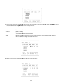
3.5
3.6
Preset
Function
MAX. 127 positions are programmable. The Preset number can be assigned from 1 to 128
except 95. Preset 95 is reserved for entering into OSD menu. Camera parameters such as
White Balance, Auto Exposure and others can be set up independently and each preset can
have its own parameter values independently from the other persets
persets. When setting up
presets with a controller, Label should be blank and "Camera Adjust" should be set to
"GLOBAL" as the default. To
o change the parameters, enter into OSD menu.
Setting Presets
Set Preset [1~128]
Running Presets
Go Preset [1~128]
Deleting Presets
To delete Presets, enter into OSD menu.
Swing
Function
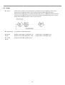
This function is that the camera moves repetitively between two preset positions at
programmed speeds. When a swing function runs, the camera moves from the preset
assigned as the 1st point to the preset assigned as the 2nd point in CW(Clockwise) direction.
Then the camera moves from the preset assigned as the 2nd point to the preset assigned as
the 1st point in CCW(Counterclockwise) direction.
In case that the preset assigned as the 1st point and the preset assigned as the 2nd point are
same, the camera turns on its axis by 360
360 in CW(Clockwise) direction
ction and then it turns back
on its axis by 360
360 in CCW (Counterclockwise) direction. The Swing speed is defined from
1/sec
/sec to 180/sec.
180
Setting Swings
To set Swing, enter into OSD menu.
Running Swings
Method 1) <Run Pattern> [Swing NO. + 10]
ex) Run Swing 3 : <Run Pattern> [13]
Method 2) <Go Preset> [Swing NO. + 140]
ex) Run Swing 3 : <Go Preset> [143]
Deleting Swings
To delete Swings, enter into OSD menu.
34
3.7
Pattern
Function
This function is that the camera memorizes the path (mostly curve path) by the joystick of the
controller and revives the trajectory operated by joystick as closely as possible.
MAX. 4 Patterns are programmable and Maximum 1200 communication commands can be
programmed in a pattern.
Setting Patterns
A Pattern can be created by the following methods.
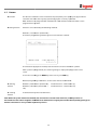
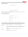
Method 1) <Set Pattern>
Pattern [Pattern NO.]
The Pattern programming window appears on the monitor as below.
The movement by Joystick and the preset movement can be memorized in a pattern.
After a pattern is programmed, the remaining storage is displayed in progress bar on the
screen.
To save the recording, press NEAR key and to cancel, press FAR key.
Method 2) Programming in OSD Menu : See the section “How
How to use OSD Menu
Menu”.
Running
Patterns
Method 1) <Run
Run Pattern> [Pattern NO.]
Ex: Run Pattern 2 : <Run Pattern> [2]
Method 2) <Go Preset> [Pattern NO. +
130]
Ex: Run Pattern 2 : <Go Preset> [132]
Deleting
Patterns
To delete Patterns, enter into OSD menu.
Note: When the system memorizes Patterns, the commands
commands are stored in the momories, not the positions of
Pan/Tilt/Zoom. Hence there might be small differences between the original path and the revived path by path type of
Patterns. Note that it is not a problem in position precision.
35
3.8
Group
Function
This function is that the camera memorizes the combination of Presets,
s, Pattern and/or Swings
sequently and runs Presets,
Preset Pattern and/or Swings repetitively. MAX. 8 sets of Group are
programmable. Each group can have MAX. 20 actions which are the combinati
combination of Preset, Pattern
and Swing. Preset speed can be set up and the repeat number of Pattern & Swing can be set up in
Group setup. Dwell time between actions can be set up also.
Setting Groups
To set Groups, enter into OSD menu.
Running
Groups
Method
thod 1) <Run Pattern> [Group NO. + 20]
ex) Run Group 7 : <Run Pattern> [27]
Method 2) <Go Preset> [Group NO. + 150]
ex) Run Group 7 : <Go Preset> [157]
Deleting
Groups
To delete Groups, enter into OSD menu.
36
3.9
Other Functions
Power Up
Action
This setting defines a specific activity (Preset, Pattern, Swing and Group) to be performed in the
event that the power to the camera is cycled. This function enables the user to resume, after
turning on power, the last action being executed before turning off the power. Most of actions
such as Preset, Pattern, Swing and Group are available for this function but Jog actions are not
available to resume.
Auto Flip
In case that tilt angle arrives at the top of tilt orbit(90°), zoom module camera turns on its axis by
180° at the top of tilt orbit and moves to opposite tilt direction (180°) to keep tracing targets.
Parking Action
This feature allows the camera to begin a specified operation after a programmed time of
inactivity. This function makes the camera automatically run a pre-defined action if there is no
command from controller for a pre-defined time period. “Wait Time” means how long a camera
should wait for from the previous-last (most recent) command before running the pre-defined
action. It can be set to 1 second ~ 3 hours.
Alarm Input
3 Alarm Inputs are available. When external sensors activate, the camera runs pre-defined actions
such as Preset, Pattern, Swing and Group. After the pre-defined time period passed, “Post Alarm”
activates, which is pre-defined. Note that only the latest alarm input is effective when multiple
sensors are activated at the same time.
Privacy Zone
Mask
Privacy Zone Mask allows the user to program 8 rectangulars that can not be viewed by the
operator of the system. To protect others’ privacy, MAX. 8 Privacy Masks can be created on the
arbitrary position to hide objects such as windows, shops or private house. With the Spherical
Coordinates system, powerful Privacy Zone Mask function is possible. A mask area will move with
pan and tilt functions and automatically adjust in size as the lens zooms telephoto and wide.
GLOBAL/LOCAL
WB(White Balance) and AE(Auto Exposure) can be set up independently for each preset. There are
2 modes, "Global" mode & "Local" mode. The Global mode is that WB and/or AE are/is set up
totally and simultaneously for all presets. The Global parameter setup such as WB and AE can be
done in "ZOOM CAMERA SETUP" menu. The Local mode is that WB and/or AE are/is set up
independently or separately for each preset. The Local parameter setup for WB and AE can be
done in each preset setup menu. Each Local parameter such as WB and AE activates
correspondingly when the camera arrives at each preset position. During jog operation, Global
WB/AE value should be applied. All Local WB/AE values do not change although Global WB/AE
value changes. The Local mode has the prior to the Global mode.
Image Setup
Semi-Auto
Focus
This mode automatically exchanges focus modes between Manual Focus mode and Auto Focus
mode by operation. Manual Focus mode activates in preset operation and Auto Focus mode
activates during jog operation. With Manual mode at presets, Focus data is memorized in each
preset in advance and the camera calls focus data in correspondence with presets as soon as the
camera arrives at presets. It should shorten time to get focuses. The focus mode automatically
changes to Auto Focus mode when jog operation starts.
37
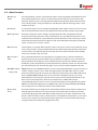
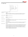
3.10 OSD Display
P/T/Z Information
Displays the amount of pan from zero degree vertical, the amount of tilt from zero degree
horizontal and current
c
compass direction. Also identifies the amount of the zoom
magnification.
Camera ID
Displays the selected Camera ID (Address).
Action Title
Identfies Actions
"SET PRESET xxx"
When Preset xxx is memorized.
"PRESET xxx"
When the camera reaches Preset xxx.
"PATTERN x"
When Pattern x is in action.
"SWG/PRESET
/PRESET xxx"
When Swing x is in action. Displays both of Swing number and
Preset number.
"UNDEFINED"
When a undefined function is called to run
Preset Label
Displays preset labels when the camera arrives at presets.
Alarm Information
Displays activated alarms. This information shows current state of Alarm IInputs and Relay
Outputs. If an Input
nput point is ON state, it will show a number corresponding to each point. If an
Input point is OFF state, '-' will be displayed.
Example: The point
p
2 & 3 of inputs are ON and Output is ON, OSD will show as below
below.
38
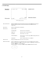
4 OSD MENU
4.1
4.2
Quick Programming Guide
The menu items with < > always have
ve sub-menus.
To go to submenuss or make the cursor move to the right,
right press NEAR key.
To go to the previous-upper level menus,
menu press FAR key.
To make a selection, press NEAR key
To cancel a selection, press FAR key
To move the cursor in the menu, use the joystick to the Up/Down direction or Left/Right direction.
To change a value of an item, use Up/Down of the joystick in the controller.
To save changes, press NEAR key.
To cancel changes, press FAR key.
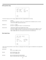
Main Menu
System Information
Displays the system information and configuration. The system setting can not be
changed using the OSD menu and the information is for reference only.
Display Setup
Enables the user to program how labels are displayed on the monitor.
Dome Camera Setup
Enables the user to configure various functions of the camera.
System Initialize
Initializes all system configurations and all data to the factory
actory default parameters.
39
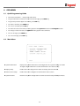
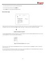
4.3
Display setup
Display setup allows you to program how labels are displayed on the monitor. In case of AUTO, the labels are displayed on
the monitor when there are any changes in parameters.
Camera ID
[ON/OFF]
Displays the selected Camera ID (Address).
PTZ Information
[ON/OFF/AUTO]
Displays the amount of pan from zero degree vertical, the amount of tilt from zero degree
horizontal and current
c
compass direction. Also identifies the amount of the zoom magnification.
Action Title
[ON/OFF/AUTO]
Identfies Actions.
"SET PRESET xxx"
"PRESET xxx"
"PATTERN x"
"SWG/PRESET xxx"
"UNDEFINED"
Preset Label
[ON/OFF/AUTO]
Displays the preset labels when the camera arrives at presets.
Alarm I/O
[ON/OFF/AUTO]
Displays the activated alarms. This information shows the current state of Alarm IInputs and Relay
Outputs. If an Input
nput point is ON state, it will show a number corresponding to each point. If an
Input point is OFF state, '-' will be displayed.
Example: The point
oint 2 & 3 of inputs are ON and Output is ON, OSD will show as below
below.
40
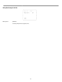
Compass Direction setup
Move the camera to a target position and press NEAR button to save the direction as North. The direction is the reference
direction to assign other compass directions
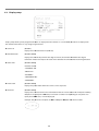
4.4
Privacy Zone Mask Setup
Privacy Zone Mask allows the user to program 4 rectangulars that can not be viewed by the operator of the system. TTo
protect privacy, MAX. 4 Privacy Masks
asks can be created on the arbitrary position to hide objects such as windows, shops or
private house. With the Spherical Coordinates system, powerful Privacy Zone Mask
Mask function is possible. A mask area will
move with pan and tilt functions and automatically adjust in size as the lens zooms telephoto and wide.
Mask NO
[1~8]
Selects a Mask number to program. If the selected mask has already data, the camera moves as it
was programmed.
programmed Otherwise, “UNDEFINED” will be displayed under the Mask number.
Display
[ON/OFF]
Sets if the mask of the selected mask number shows or not on the screen.
Clear Mask
[CANCEL/OK]
Deletes the mask data of the selected mask number.
41
Privacy Zone Mask Area Setup
Move your camera to an area to mask. Then a mask and the menu to adjust the mask size will be displayed.
Privacy Zone Mask Size Setup
Adjusts the mask size. Use the joystick or the arrow buttons of your controller to adjust mask size.
(Left/Right)
Adjusts the mask width.
(Up/Down)
Adjusts the mask height.
42
4.5
Camera Setup (Dome Camera Setup Menu)
Sets the general functions of zoom camera module.
Focus Mode
[AUTO/MANUAL/SEMIAUTO]
Sets camera Focus mode.
SEMIAUTO Mode
This mode automatically exchanges focus modes between Manual Focus mode and Auto Focus
mode by operation. Manual Focus mode activates in preset operation and Auto Focus mode activates
during jog operation. With Manual mode at presets,
presets, Focus data is memorized in each preset in
advance and the camera calls focus data in correspondence with presets as soon as camera arrives at
presets. It should shorten time to get focuses.
focuses Focus mode automatically changes to Auto Focus
mode when jog operation
ration starts.
Digital Zoom
[ON/OFF]
Sets the digital zoom functions to ON/OFF. If this is set to OFF, the optical zoom function runs but the
zoom function stops at the end of optical zoom magnification.
Image Flip
[ON/OFF]
Sets System Image Flip Function to ON/OFF. When
hen this function is set to ON, flipped images always
come out. When the camera is installed as Desktop type, set to ON to get proper images.
Sharpness
[0~3]
Sets image sharpness to enhance pictures.
43
White Balance Setup
WB Mode
[AUTO/MANUAL]
Retains color balance over a color temperature range. In auto mode, this feature automatically
processes the viewed image. In Manual mode, Red and Blue level can be set up manually.
Red Adjust
[10~255]
Adjusts the picture output in the red range.
Blue Adjust
[10~255]
Adjusts the picture output in the blue range.
Auto Exposure Setup
Backlight
[ON/OFF]
Sets Backlight Compensation to ON/OFF. If a bright backlight is present, the subjects in the picture
may appear dark or as a silhouette. Backlight compensation enhances objects in the center of the
picture.. The camera uses the center of the picture to adjust the iris. If there is a bright light source
outside of this area, it will wash out to white. The camera
camera will adjust the iris so that the object in the
sensitive area is properly exposed.
Day/Night
[AUTO//DAY/NIGHT]
Sets Day&Night mode. You can increase sensitivity in low light conditions by switching to black
blackwhite mode (removing the IR cut filter or turning on DSS). Color mode is preferred in normal
lighting conditions. The time to change a mode is 10 sec.
. If this is set to DAY mode, ACG is fixed to HIGH.
44
Brightness
[0~64]
Adjusts the brightness of the images. Iris, The Shutter Speed and Gain are adjusted automatically in
correspondence with each numeric value.
IRIS
[AUTO/MANUAL(0~64)]
Sets Iris to operate automatically or at a user-defined level. If Iris is set to Auto, Iris has higher
priority in adjusting AE and Shutter Speed is fixed. Auto iris is the lens function that automatically
opens closes the iris in response to changing light conditions.
If Iris is set to Manual, Iris is fixed and Iris has lower priority in adjusting AE, in comparison with
others. The Iris level range is 0 ~ 100.
Shutter Speed
[A.Flicker/Manual(1/60(50) ~ 1/10000 sec)]
Sets Shutter Speed. Shutter Speed is the duration of the electronic shutter. If Iris is set to Manual
and Shutter Speed is set to ESC, Shutter Speed has higher priority. If Shutter Speed is set to
A.Flicker, to remove Flicker, Shutter Speed should be set to 1/100 sec. for NTSC and 1/120 for PAL.
AGC
[OFF/LOW/HIGH]
Sets AGC. This setting enhances image brightness automatically in case that luminance level of
image signal is too low.
SSNR
[OFF/LOW/MIDDLE/HIGH]
Sets SSNR. This setting enhances the images by deducting noises when the gain level of the mages
is too high.
SENS-UP
[AUTO(2~256)/OFF]
Sets SENS-UP. This setting activates Slow Shutter function when luminance of image (signal) is too
dark.
It is possible to set up the maximum number of frames piled up one on another by Slow Shutter
function.
(Wide Dynamic Range) Setup
Limit
[LOW/MIDDLE/HIGH]
Level
[0~100]
45
HLC (High Light Compensation) Setup
Limit
[AUTO/MANUAL]
When there are too bright lights, this function blocks light sources on the images to have
better images. For example, when there is a car coming to a camera at night, this function
bocks car headlights to recognize its number plate.
Level
[0~10]
Assigns colors of masks to block light sources
46
4.6
Motion Setup
Sets the general functions of Pan/Tilt motions.
Motion Lock
[ON/OFF]
If Motion Lock is set to ON, it is impossible to set up and delete Preset, Swing, Pattern and Group. It is
possible only to run those functions. To set up and delete those functions, eenter into OSD menu.
Power Up Action
[ON/OFF]
Refer to “Other
Other Functions" section.
Auto Flip
[ON/OFF]
Refer to “Other
Other Functions" section.
Jog Max Speed
[1/sec ~360/sec]
Sets the maximum jog speed. Jog speed is inversely proportional to the zoom magnifications. As the zoom
magnification goes up, the pan/tilt speed goes down.
Jog Direction
[INVERSE/NORMAL]
Sets the Jog Direction. If this is set to ‘Inverse’,, the view direction in the screen is same as the direction of
joystick. If this is set to ‘Normal’,, the view direction in the screen is the reverse dirction of joystick.
Freeze in Preset
[ON/OFF]
Sets Frame Freeze Function. This feature freezes the scene
scene on the monitor when going to a preset. At the
start point of a preset movement, a camera starts freezing the image of the start point. Camera keeps
displaying the image of the start point during preset movement and does not display the images which
camera
ra gets during preset movement. As soon as camera stops at preset end point, camera starts
displaying live images which it gets at the end preset point. This feature also reduces bandwidth when
working with digital systems or digital network systems.
This function
unction availability should be different by models.
models
47
Parking Action Setup
This feature allows the camera to begin a specified action after a programmed time of inactivity.
Park Enable
[ON/OFF]
If Park Enable is set to ON, the camera runs an assigned function automatically if there is no PTZ
command during the programmed "Wait Time".
Wait Time
[1~59 sec. / 1~180 min.]
Wait Time can be programmed from 1 second to 180 minutes.
Park Action
[HOME/PRESET/PATTERN/SWING/GROUP/PREV ACTION]
This feature defines the activity when the camera parks. If Park Action is set to “HOME”, the camera
moves to the home position which is memorized when the system boots. If Park Action is set to
“PREV. ACTION”,, the camera runs the previous action which it ran most recently.
Alarm Input Setup
Defines Alarm Function. When an alarm is receive, an input signal to the camera triggers the user
user-defined action programmed
for the alarm.
Alarm No
[1~3]
Selects a sensor number to set up.
Type
[Normal OPEN/Normal CLOSE]
Selects sensor operation type.
Action
[NOT USED/PRESET/PATTERN/SWING/GROUP]
Selects an action to run when a sensor signal is input.
48
Hold Time
[ENDLESS / 1~59 SEC. / 1~180 MIN.]
Sets the time period for the action which is run by external sensor activation. After the time period
passes, the action pre-defined in “Post Action” runs sequentially in succession to the action by external
sensor activation. If this option is set to “ENDLESS”, “Post Action” does not activate.
Post Action
[HOME/PRESET/PATTERN/SWING/GROUP/PREV ACTION]
Selects the action that a camera will run after the time period in“HOLD TIME” passes. If Post Action is
set to “PREV. ACTION”, the camera runs the previous action which it ran most recently.
49
4.7
Preset Setup
Preset Number
[1~128]
Selects a preset number to set up. If a selected preset is already defined, the camera moves to the
pre-defined
defined position and preset parameters such as Label and CAM Adjust show on the monitor. If a
selected preset is not defined, “UNDEFINED” shows on the monitor.
Clear Preset
[CANCEL/OK]
Deletes the data of the selected Preset.
Edit Preset Scene
Re-defines
defines the scene position of the selected Preset.
Edit Preset Label
Edits the label of the selected Preset to show on the monitor when the preset runs. MAX. 10
alphanuberic characteristics are allowed.
Relay Out
Defines the relay output.
CAM Adjust
[GLOBAL/LOCAL]
WB(White Balance) and AE(Auto Exposure) can be set up independently for each preset. There are 2
modes, "Global" mode & "Local" mode. The Global mode is that WB and/or AE are/is set up totally and
simultaneously for all presets. The Global parameter setup such as WB and AE can be done in "ZOOM
CAMERA SETUP" menu. The Local mode is that WB and/or AE are/is set up independen
independently or
separately for each preset. The Local parameter setup for WB and AE can be done in each preset
setup menu. Each Local parameter such as WB and AE activates correspondingly when the camera
arrives at each preset position. During jog operation, Global WB/AE value should be applied. All Local
WB/AE values do not change although Global WB/AE value changes. The Local mode has the prior to
the Global mode.
Preset Scene Setup
50
○,1 Use the Joystick to move the camera to a desired position.
○,2 Save the preset position by pressing NEAR key.
○,3 Press FAR key to cancel targeting the preset position.
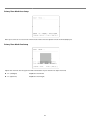
Preset Label Setup
Edit the label of the selected preset to show on the monitor when camera arrives at the preset. In the Edit Label menu, the dark
rectangular is the cursor. As soon as finishing selecting an alphabet or a number, the cursor moves to the next digit.
1) With Left/Right/Up/Down of the joystick, move to a desired Alphabet or a desired number in the Alphanumeric set. To select
a desired Alphabet or a desired number, press the NEAR key.
If you want to use a blank, select the double quotation mark (" "). If you want to delete an Alphabet or a number, use the back
space character (" ").
2) If you complete the Label editing, move the cursor to "OK" and press the NEAR key to save the completed label. To abort the
current change, move the cursor to "Cancel" and press the NEAR key.
51
Relay Out Setup (4 305 22)
Relay Out
[ON/OFF]
Sets Relay Outputs for assigned preset.
52
4.8
Swing Setup
Swing Number
[1~8]
Selects a Swing number to edit. If the selected Swing is not defined, "NOT USED" is displayed in
the 1st Position and the 2nd Position.
1st Position
2nd Position
[PRESET 1~128]
Sets the 2 positions for a Swing function. If the selected preset is not defined, "UNDEFINED" is
displayed as shown below.
When a swing function runs, the camera moves from the preset assigned as the 1st point to the
preset assigned
ssigned as the 2nd point in CW(Clockwise)
CW(Clock
direction. Then the camera moves from the
preset assigned as the 2nd point to the preset assigned as the 1st point in CCW
(Counterclockwise) direction. In case that the preset assigned as the 1st point and the preset
assigned as the 2nd point are same or only 1 Preset position is assigned, the camera turns on its
axis by 360 in CW direction and then it turns on its axis by 360
360 in CCW directi
direction.
Swing Speed
[1/sec. ~180/sec.]
Defines Swing speed
peed between the 2 Preset positions from 1/sec to 180/sec
Clear Swing
[CANCEL/OK]
Deletes the data of the selected Swing.
Run Swing
Runs Swing for the test purposes to check if it works properly.
53
4.9
Pattern Setup
Pattern Number
[1~4 ]
Selects a Pattern number to edit. If the selected pattern number is not defined, "UNDEFINED" will
be displayed under the selected pattern number.
Clear Pattern
[CANCEL/OK]
Deletes the data of the selected pattern.
Run Pattern
Runs the Pattern for the test purposes to check if it works properly.
Edit Pattern
Edits the selected pattern.
Pattern Edit
1)
With the Joystick of your controller, move the camera to the start position with an appropri
appropriate zoom magnafication. To
start the pattern recording, press NEAR key. To exit, press FAR key.
2)
Move camera with joystick of controller or run preset function to memorize the path (mostly curve path) in the selected
pattern. The movement by Joystick and preset movement will be memorized in a pattern. After a pattern is
programmed, the remaining storage is displayed in progress bar on the screen.
3)
To save the data and exit, press NEA
EAR key. To cancel saving the data and delete the data,
ata, press FAR key.
54
4.10 Group Setup
Group Number
[1~8]
Selects a Group number to edit.
If the selected Group number is not defined, "UNDEFINED" will be displayed under
the selected Group number.
Clear Group
[CANCEL/OK]
Deletes the data of the selected Group.
Run Group
Runs the Group for the test purposes to check if it works properly.
Edit Group
Edit the selected Group.
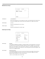
Group Edit
1)
Press Near key when the cursor is at “NO” to start editing the selected Group.
2)
Note that MAX. 20 actions are allowed in a Group. Move the cursor up/down to select an Action. Press Near key to edit.
55
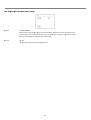
3)
Define Action, Dwell time and Option. Note that the dark rectangular is the cursor. Move the cursor Left/Right to select
an item and move cursor Up/Down to change each parameter.
Action ###
[NONE/PRESET/SWING/PATTERN]
DWELL
[0 SEC. ~ 4 MIN.]
Sets the Dwell Time between functions.
OPT
4)
Option. It is a preset speed when a preset is selected in the Action. It is the number of repeat
when a Pattern or a Swing is selected in the Action.
A
Edit the items such as Action, ###, Dwell and OPT by moving the cursor.
56
5) After finishing editing a Action, press Near key to go to the previous-upper level menu (Step
Step ②). Move the cursor
Up/Down to select an Action number and repeat Step ② ~ Step ④ to keep editing the selected Group.
6)
After finishing setting up, press FAR key to exit. Then the cursor will move to “SAVE”. Press Near key to save the data.
57
4.11 System Initialization
Clear All Data
Deletes all configuration data and the system is set to the factory default.
Clear Display Set
Initializes all the configuration data for Display.
Clear Camera Set
Initializes all the configuration data for Camera.
Clear Motion Set
Initializes all the configuration data for Motion.
Clear Edit Data
Deletes all the configuration data for Preset, Swing, Pattern and Group.
Reboot Camera
Reboots the zoom camera module.
Reboot System
Reboots the system.
58
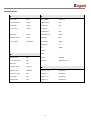
Factory Default
Display Parameters
Camera Parameters
Camera ID
ON
Focus Mode
SemiAuto
PTZ Information
AUTO
Digital Zoom
ON
Action Title
AUTO
Image Flip
OFF
Preset Label
AUTO
Sharpness
2
Stabilization
OFF
Alarm I/O
AUTO
White Balance
AUTO
North Direction
Pan 0
Backlight
OFF
Privacy Zone
Undefined
Day&Night
AUTO
Brightness
32
Iris
AUTO
Shutter
-
AGC
-
Motion Parameters
Motion Lock
OFF
SSNR
MIDDLE
Power Up Action
ON
SENS-UP
AUTO (4 Frame)
Auto Flip
ON
Jog Max Speed
120/sec
User-Defined Data
Jog Direction
INVERSE
Preset 1~128
Undefined
Freeze In Preset
OFF
Swing 1~8
Undefined
Park Action
OFF
Pattern 1~4
Undefined
Alarm Action
OFF
Group 1~8
Undefined
59
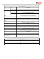
5 Specifications
CAMERA PART (4 305 21/4 305 23)
Video Signal Format
PAL
Image Sensor
Sony 1/4'' Super HAD CCD
Total Pixels
795(H)596(V) 470K
Effective Pixels
752(H)582(V) 440K
Horizontal Resolution
560 TV Lines(Color), 600 TV Lines(B/W)
Video Signal-to-Noise
52 dB (AGC Off)
Zoom
12x Optical Zoom, 12x Digital Zoom
Forcal Length
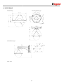
F1.6 (Wide)/F2.0(Tele), f=3.6~44.3 mm
Angle of View
H : 5444(Wide)~4.64(Tele) / V : 41.42(Wide)~3.52(Tele)
Minimum Illuminance
2.0 Lux (Color, Sens Off) / 0. 0008 Lux (B/W, Sens x256), 50 IRE, F1.6
Day & Night
Auto / Day / Night(ICR)
Focus
Auto / Manual / SemiAuto
Iris
Auto / Manual
Shutter Speed
1/60(50) ~ 1/10000 sec (x2~ 256 Sens UP)
AGC
Auto / Manual
White Balance
Auto / Manual(Red, Blue Gain Adjustable. 2000K~10000K)
BLC
ON/ Off
Flickerless
Selectable
SSNR
Low / Middle / High / Off
Privacy Zone
8 Masks, Spherical Coordinate
60
Specifications (4 305 22)
Model
4 305 22
Video Signal System
PAL
CCD
1/4'' Super HAD color CCD
Max. Pixels
795(H)596(V) 470K
Effective Pixels
752(H)582(V) 440K
Horizontal Res.
550 TV Line(Color), 680 TV Line(B/W)
S/N Ratio
50 dB (AGC Off)
Zoom
27x Optical Zoom, 12x Digital Zoom
Focal length
f=3.5~94.5mm (F1.6~2.9)
Min. illumination
Camera
0.4 Lux/F1.6 (Color), 0. 02 Lux/F1.6 (B/W), 50 IRE
Day & Night
Auto / Day / Night(ICR)
Focus
Auto / Manual / SemiAuto
Iris
Auto / Manual
Shutter Speed
x256 ~ 1/120000 sec
AGC
Low / Middle / High / Manual / Off
White Balance
Auto / Manual(Red, Blue Gain Adjustable)
BLC
BLC / HLC / Off
Flickerless
Selectable
SSNR
Low / Middle / High / Off
Stabilization
On / Off
Range
Pan/Tilt Speed
Pan/Tilt
Pan 360(Endless) / Tilt 95
Preset :
360/sec
Manual :
0.05 ~ 360/sec (proportional to zoom)
Swing :
1~ 180/sec
Preset
127 Preset (Label, Camera Image Setting)
Pattern
4 Pattern, 1200 commands(about 5 minute)/Pattern
Swing
8 Swing
Group
8 Group (20 action entities per Group)
Other Functions
Auto Flip, Auto Parking, Power Up Action etc.
Communication
RS-485
Protocol
Pelco-D, Pelco-P selectable
Alarm I/O
4 Input / 2 Output
Privacy Mask Zone
General
8 Zone
OSD
Dimension
Menu / PTZ information etc.
Dome :
149
Housing :
160 212(H) mm
Weight
about 2 kg
Operating Temp.
0C ~ 40C
* Specifications of this product can be subjected to change without notice.
61
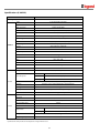
Specifications (4 305 24 – 4 305 25
CAMERA PART
4 305 24
4 305 25
Video Signal Format
PAL
Image Sensor
1/4'' Interline Transfer CCD
Total Pixels
795(H)596(V) 470 K
Effective Pixels
752(H)582(V) 440 K
Horizontal Resolution
550 TV Lines(Color), 680 TV Lines(B/W)
Video Signal-to-Noise
50 dB (AGC Off)
Optical Zoom
27x
37x
Digital Zoom
12x
Forcal Length
F1.6~2.9, f=3.5~94.5 mm
F1.6~3.9, f=3.5~129.5 mm
Angle of View (H)
55.5(Wide)~2.24(Tele)
55.5(Wide)~1.59(Tele)
Angle of View (V)
42.5(Wide)~1.79(Tele)
42.5(Wide)~1.19(Tele)
1.8 sec
2.5 sec
0.4 Lux (Color) / 0.02 Lux (B/W), 50 IRE
/ F1.6
0.7 Lux (Color) / 0. 6 Lux
(B/W), 50 IRE / F1.6
Zoom Speed (Wide to Tele)
Minimum Illuminance
Day & Night
Auto / Day / Night(ICR)
Focus
Auto / Manual / SemiAuto
Iris
Auto / Manual
Shutter Speed
256 ~ 1/120000 sec
AGC
Low/Middle/High/Manual/Off
Auto / Manual(Red, Blue Gain Adjustable.
1800 K~10500 K)
White Balance
BLC
BLC/HLC/Off
Flickerless
WDR/BLC/HLC/Off
Selectable
SSNR
Low / Middle / High / Off
Stabilization
ON/OFF
Privacy Zone
8 Masks, Spherical Coordinate
62
MECHANISM PART
Pan
360(Endless)
Tilt
90
Movement Range
Preset
Speed
360/sec.
Jog
0.05 ~ 360/sec. (Proportional to Zoom)
Swing
1~ 180/sec.
Preset
127 Presets (Label, Independent Camera Parameter Setting)
Pattern
4 Patterns [1200 Commands(Approx. 5 Minute) / Pattern]
Swing
8 Swings
Group
8 Groups (MAX. 20 Actions with The Combination of Preset, Pattern and
Swing)
Other Pan/Tilt Functions
Auto Flip, Auto Parking, Power Up Action and etc.
Communication
RS-485
Protocol
Pelco-D, Pelco-P Selectable
OSD
English, Menu / PTZ information etc
Sensor Input
Alarm Outputs
3 Inputs, Photo-Coupler Type, DC 5V~12V
1 Output, Relay Output, MAX. Load DC24V 1A / AC125V 0.5A
Fan
Heater
Always ON
Operation Start from Internal Temperature 10C
0C ~ 40C (4 305 21/4 305 22 Models)
Operation Temperature
-30C ~ 50C (4 305 23/4 305 24/4 305 25 Models)
RATED POWER
4 305 21
DC 12V / 0.8 A
4 305 22
DC 12 V / 0.75 A
4 305 23/4 305 24/4 305 25
DC 12V / 2.5 A
63
MECHANICAL
4 305 21 Model
Surface Mount
Ceiling Mount
Dome
Material
Wall Mount
Polycarbonate
Internal
Polycarbonate, ABS
External
Polycarbonate
Dome Size
107.5 mm / 4.2”
Dimension
132.4129.5 mm
132.4187.5 mm
213.2207.5 mm
Weight (kg)
Approx 0.7
Approx 0.8
Approx 0.85 kg
MECHANICAL
4 305 23 Model
Ceiling Mount
Wall Mount
Dome
Material
Dome Size
[Note]
1)
4 305 24/4 305 25 Models
Ceiling Mount
Wall Mount
Polycarbonate
Internal
Polycarbonate, ABS
External
Aluminium
107. 5mm / 4.2”
150mm / 5.9”
Dimension
158.2216 mm
274.5227.3 mm
192x265.3mm
296x276.6mm
Weight (kg)
Approx 2.6 kg
Approx 2.8 kg
Approx 3.2 kg
Approx 3.8 kg
Specification and features are subject to change without prior notice.
2)
Specification and features are different by models.
3)
Check the voltage and current capacity of rated power carefully.
64
5.1
Dimension
(4 305 21 Model)
Main Body
Surface Mount Type
[Unit : mm]
65
(4 305 22 Model)
Main Body & Terminal Cover
In-Ceiling Mount Bracket
Ceiling Mount Bracket
Wall Mount Bracket
Unit (mm)
66
(4 305 23 Model)
Main Body
Ceiling Mount Type
Wall Mount Type
[Unit : mm]
67
(4 305 24/4 305 25 Model)
Main Body
Ceiling Mount Type
Wall Mount Type
[Unit : mm]
68