1
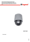
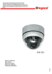
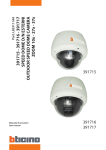
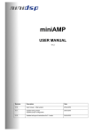
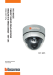
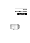
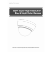
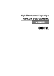
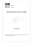
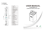
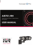
s¬Caméra couleur dôme motorisée jour/nuit 3,8-38 mm 10X
s¬3.8-38 mm 10X motorized day/night dome colour camera
s¬Cámara de cúpula en color motorizada día/noche 3,8-38 mm 10X
s¬Câmara a cores cúpula motorizada diurna/nocturna 3,8-38 mm 10X
s¬kamera kolorowa ze sklepieniem, z napędem, dzień/noc 3,8–38 mm 10X
430 521
430 521
LE03664AA
User manual
FEATURES
s¬ Powerful Zoom Camera & Setup Options
10x Optical Zoom, 10x Digital Zoom (100x Max. zoom magnification)
High light compensation
Privacy Mask
Day & Night
Focus Mode : Auto-Focus, Manual Focus, Semi-Auto Focus
OSD Menu
Image Sensor : ¼” Sony interline Transfer CCD
s¬
Powerful Pan/Tilt Functions
~
~
~
s¬
MAX. 360°/sec High Speed Pan/Tilt Motion
With the Vector Drive Technology, Pan/Tilt motions are accomplished along the shortest path.
As a result, the time to target view is remarkably short and the video on the monitor is very natural in
monitoring.
With the Micro-Stepping Control Technology, the video looks very natural at high zoom magnification
during a jog operation on a controller since the camera can be controlled by 0.05°/sec. Hence it is very
easy to make the camera focus on desired target views at high zoom magnification. Additionally it is easy
to make the camera focus on desired positions with zoom-proportional pan/tilt movement.
Preset, Pattern, Swing, Group, Privacy Mask and More…
~
~
MAX. 127 Presets are programmable and each preset can have its own parameter values independently
from the other presets.
For an example, refer to the below table.
Preset No.
White Balance
Auto Exposure
Preset 1
Case A
Case 3
“ENTRANCE”
Preset 2
Case C
Case 5
“WAREHOUSE”
Preset 3
Case V
Case 2
“OFFICE”
-
-
Case K
Case 9
sss
Label
Remarks
~~~
Preset 95
-
-
Reserved for
OSD Menu
~~~
Preset 128
“TERRACE”
~
MAX. 8 sets of Swing are programmable. This function is that the camera moves repetitively between two
preset positions at programmed speeds.
~
MAX. 4 Patterns are programmable. This function is that the camera memorizes the path (mostly curve
path) by the joystick of the controller and revives the trajectory operated by the joystick as closely as
possible.
~
MAX. 8 sets of Group are programmable. This function is that the camera memorizes the combination of
Presets,
Pattern and/or Swings sequently and runs Presets, Pattern and/or Swings repetitively.
A Group can be combined upto 20 functions with any of Preset/Pattern/Swing.
~
4 Privacy Masks are programmable, not to intrude on any other’s privacy :
2
s¬ PTZ (Pan/Tilt/Zoom) Control
~ With the RS-485 communication connection, MAX. 255 units of cameras can be connected to a single
controller.
~ Pelco-D or Pelco-P protocols can be selected as a control protocol in the current firmware version.
s¬ OSD (On Screen Display) Menu
~
~
OSD menu is provided to display the status of camera and to configure the functions interactively.
The information such as Camera ID, Pan/Tilt Angle, Direction, Alarm Input and Preset is displayed on
screen.
s¬ Alarm In/Out Function
~
~
~
~
3 alarm sensor inputs and 1 alarm sensor outputs
Alarm sensor input is decoupled with photo-couplers to avoid external electric noise and shock perfectly.
Both of N.O.(Normal Open) sensors and N.C.(Normal Close) sensors can be used and the signal range of
the sensor input is from DC 5.0V to 12.0V for various applications.
The camera can be set to move to a Preset position or to run functions such as Pattern, Swing and Group
when there are external sensor activations. Also “Post Alarm” function is possible, which is supposed to
activate after user-defined time period and sequentially in succession to the action by external sensor
activations.
s¬ Reserved Presets (Hot Keys)
~
Most camera setup options can be set up easily and directly with the reserved presets (Hot Keys), without
entering into OSD menu. For more information, refer to “Reserved Presets (Hot Keys)”.
Warning
- The installation and calibration of this camera must be carried out by highly skilled personnel.
- Do not open the camera: there may be a risk of electric shock.
- Low voltage cameras must be powered by a power supply unit with stabilized voltage.
This range of cameras has been created for CCTV applications and not for other uses.
Use these cameras only for the following temperature conditions: from (-10) – (+50) °C.
Do not use the cameras with voltages different from the ones specified.
Safety instructions
This product should be installed in line with installation rules, preferably by a qualified electrician. Incorrect installation and use can lead to risk of electric shock or fire.
Before carrying out the installation, read the instructions and take account of the product’s specific mounting location.
Do not open up, dismantle, alter or modify the device except where specifically required to do so by the instructions. All Legrand products must be opened and repaired exclusively by personnel trained
and approved by Legrand. Any unauthorised opening or repair completely cancels all liabilities and the rights to replacement and guarantees.
Use only Legrand brand accessories.
3
PACKAGE COMPONENT
s¬ Product & Accessories
4
MAIN PART DESCRIPTION
s¬ Product & Accessories
Surface Mount B racket
Mounting Screw Hole
Main Connector
Sensor I/O Port
Dome Cover
A ssembly Stud
DIP Switch
Dome Cover L ock-up Screw
Dome Cover
~
Dome Cover
Do not detach the protection vinyl from the dome cover before finishing all the installation process to protect
the dome cover from scratches or dust.
~
Dome Cover Lock-up Screw
Used to lock up the dome cover after assembling the dome cover with the main body.
~
Dome Cover Assembly Stud
Used to line up the stud on the main body and the stud on the dome cover when assembling the dome cover
with the main body.
~
DIP Switch
Used to set up camera IDs and protocols.
~
Surface Mount Bracket & Mounting Screw Hole
Used for surface mount type, wall mount type and ceiling mount type. They are not used for in-ceiling mount
type.
~
Main Connector
Used for the power wire, the video cable and the RS-485 communication cable connection.
~
Sensor I/O Port
Used for the sensor in/out connection.
5
DIP SWITCH SETUP
Before installing the camera, set up the DIP switch to configure the camera ID and the communication protocol.
s¬ Product & Accessories
s¬ Camera ID Setup
~
~
~
~
~
~
DID numbers of cameras are set up with binary numbers. See the examples shown below.
Pin
1
2
3
4
5
6
7
8
Binary Value
1
2
4
8
16
32
64
128
ex: ID = 5
ex: ID = 10
on
off
off
on
on
off
off
on
off
off
off
off
off
off
off
off
The camera ID range is “1~255”. Camera ID must not be “0”!
The factory default of the camera ID is “1”.
Match the camera ID with the Cam ID setting of your DVR or Controller to control the camera.
If you are connecting a single camera to a controller, terminate the camera. When connecting more than one
camera to a single controller, terminate the last camera on the communication line. The last camera means
the camera farthest in cable length from the controller.
Note that the total length of the communication cable between a controller and the camera(s) on the same
communication line must be less than 1.2Km.
6
s¬ Communication Protocol Setup
~ Select an appropriate Protocol with the DIP switch combination.
Switch Mode
P0
(Pin 1)
P1
(Pin 2)
P2
(Pin 3)
Protocol
OFF
OFF
OFF
PELCO-D, 2400 bps
ON
OFF
OFF
PELCO-D, 9600 bps
OFF
ON
OFF
PELCO-P, 4800 bps
ON
ON
OFF
PELCO-P, 9600 bps
Others
Reserved
~ Match the camera protocol with the camera protocol in the setting of your DVR or controller to control the
camera.
~ Adjust the DIP switch after turning off the camera. If you changed the camera protocol by changing the
DIP S/W, the change will be effective after you reboot the camera.
The factory default protocol is “Pelco-D, 2400 bps”.
s¬ Terminal Resistor Setup
~
The terminal resistor is used for the following cases.
s¬
Case 1 : In case that the control cable length between a camera and a controller is relatively
very long (1:1 Connection)
If the communication cable length is very long, the electrical signal will bound in the terminal point. This
reflected signal causes distortion of original signal. Accordingly, the camera can be out of control. In
this case, the terminal resistor of both sides i.e. the camera and the controller must be set to ‘ON’ state.
s¬
Case 2 : In case that multiple cameras are connected to a controller.
Due to similar reasons with the case 1, the terminal resister of the controller and the last camera must
be set to ‘ON’ state. The last camera means the camera farthest in cable length from the controller. Do
not turn on the terminal resistor of all the cameras on the same communication cable.
The complete informations are in the manual on the CDrom.
7
$$
$
IN-CEILING MOUNT INSTALLATION
! Remove the ceiling tile from the ceiling and cut
a hole whose diameter is 110mm on the ceiling
tile to pass the wires and cables through to the
upside of ceiling.
# Align the dome cover stud with the dome cover
assembly stud and slightly push the dome cover
to the ceiling tile.
" Connect the wiring and cabling and attach the
camera to the ceiling tile. (Tapping M4x16)
''
'
$ Turn the dome cover clockwise and screw on
the dome cover lock-up screw. Then remove the
protection vinyl from the dome cover.
(Machine M3x6)
Important Notice
~ Before starting the installation, make sure that the Camera ID and Protocol are set up properly.
8
*
INSTALLATION WITH SURFACE MOUNT BRACKET
! Remove the ceiling tile from the ceiling and cut a
hole whose diameter is 30~40mm on the ceiling
tile to pass the wires and cables through to the
upside of the ceiling. (In case of wiring and
cabling through the ceiling tile only)
# Connect the wires and cables to the ports and
install the main body. (Machine M3x8).
*
!!
--
!
-
" Prepare the surface mount bracket.
Pull the wires and cables for the system as
below. Attach the surface mount bracket to the
mounting surface.
(Tapping M4x25)
$ Align the dome cover stud with the dome cover
assembly stud and slightly push the dome cover
to the ceiling. Turn the dome cover clockwise and
screw on the dome cover lock-up screw.
Then remove the protection vinyl from the dome
cover. (Machine M3x6).
Important Notice
~
~
Before starting the installation, make sure that the Camera ID and Protocol are set up properly.
When the pipe hole for wiring and cabling on side of the Surface Mount Bracket is not used, make sure that the
hole is properly sealed with the supplied Hole Plug.
9
WIRING AND CABLING
POWE R
A UDI O
MIC
. SPE A K E R
B NC
MA I N C A B L E
MONITOR
C AB L E
R S-485
I /O CA B L E
C ONT R OL L E R / DV R
SE NSOR I/O
IR
SE NSOR
DOOR
SWI TCH
s¬ Port Description
~ Main Cable
Port Pin Number (RJ45)
1
2,4
Connector / Wire Color
BNC Connector
Signal
Video +
Video -
5
Red
RS-485 +
3
Yellow
RS-485 -
7
Orange
Power +
6,8
White
Power -
Port Pin Number (RJ25)
Wire Color
Signal
1
Blue
IN COM +
2
Yellow
IN 1-
3
Green
IN 2 -
4
Red
IN 3 -
5
Black
OUT A
6
White
OUT B
Port Pin Number
Connector/Wire Color
Signal
1
RCA (Yellow)
Audio IN
~ I/O Cable
~ Audio Cable
2
3
Audio GND
RCA (White)
10
Audio OUT
s¬ Power Description
~ Carefully check the voltage and current capacity of the rated power. The rated power is indicated in the back of
main unit.
Input Voltage Range
Current Consumption
DC 11V ~ 15V
0,8 A
~ For the DC input models, be careful with the polarity of DC power. The system should be permanentally damaged
by wrong DC input.
~ In case that the length of the power wire is very long, there may be voltage drop and the syatem may not work
properly. Make the length of the power wire as short as possible.
s¬ RS-485 Communication
~ For PTZ control, connect the cable(s) to your keyboard or DVR. To connect multiple cameras to a single
controller, RS-485 communication should be connected in parallel as shown below. If you are connecting a single
camera to a controller, terminate the camera. When connecting more than one camera to a single controller,
terminate the last camera on the communication line. The last camera means the camera farthest in cable length
from the controller.
Note that the total length of the communication cable between a controller and the camera(s) on the same
communication line must be less than 1.2Km.
s¬ Video
~ Use BNC coaxial cable only.
11
s¬ Alarm Input
~ Before connecting sensors, check driving voltages and output signal types of the sensors. Since output signal
types of the sensors are divided into Open Collector type and Voltage Output type in general, the wiring must be
done properly after considering those types.
Signal
IN COM+
Description
The electric power source to drive input circuit. Connect the (+) wire of electric power
source to drive the Sensors to this port as shown in the above circuit.
IN1 -, IN2 -, Connect the outputs of sensors to each port as shown in the above circuit.
IN3 -
~ If you want to use Alarm Input, the types of sensors must be selected in OSD menu. The sensor types are
divided into Normal Open and Normal Close. If wrong sensor types are selected, alarms should be activated
reversely to sensor inputs.
Normal Open
Output Voltage is high state when sensor is activated
Normal Close
Output Voltage is high state when sensor is not activated
s¬ Relay Output
~ The maximum loads are as follows.
Power Type
DC Power
Maximum Load
MAX. DC 24V, 1A
12
CHECK POINTS BEFORE OPERATION
~ Before turning on the system, check if the wire(s) and cable(s) are connected properly.
~ Check if the camera ID on the controller is properly selected. The camera ID must be identical to that of the
target camera. The camera ID can be checked by reading the DIP switch of the camera or on OSD.
~ If your controller supports multi-protocols, the protocol must be changed to match to that of the camera.
~ Adjust the DIP switch after turning off the camera. If you changed the camera protocol by changing the DIP
S/W, the change will be effective after you reboot the camera.
~ Since the operation method can be different by controllers, refer to your controller manual if the camera can
not be controlled properly. The operation of this manual is based on the standard Pelco® Controller.
13
SPECIFICATIONS
CAMERA PART
Video Signal Format
PAL
Image Sensor
1/4'' Interline Transfer CCD
Total Pixels
795(H)x596(V) 470K
Effective Pixels
752(H)x582(V) 440K
Horizontal Resolution
500 TV Lines(Color), 570 TV Lines(B/W)
Video Signal-to-Noise
50 dB (AGC Off)
Zoom
x10 Optical Zoom, x10 Digital Zoom
Forcal Length
F1.8, f=3.8~38mm
Angle of View
H : 51.2°(Wide)~5.58°(Tele) / V : 39.3°(Wide)~4.27°(Tele)
Zoom Speed
1.75 sec (Wide to Tele)
Minimum Illuminance
0.7 Lux (Color) / 0. 02 Lux (B/W), 50 IRE
Day & Night
Auto / Day / Night(ICR)
Focus
Auto / Manual / SemiAuto
Iris
Auto / Manual
Shutter Speed
x128 ~ 1/120000 sec
AGC
Normal / High / Off
White Balance
Auto / Manual(Red, Blue Gain Adjustable. 1800°K~10500°K)
BLC
Low / Middle / High / Off
Flickerless
Selectable
SSNR
Low / Middle / High / Off
Privacy Zone
4 Masks, Spherical Coordinate
MECHANISM PART
Movement Range
Speed
Pan
360°(Endless)
Tilt
90°
Preset
360°/sec.
Jog
0.05 ~ 360°/sec. (Proportional to Zoom)
Swing
1~ 180°/sec.
Preset
127 Presets
(Label, Independent Camera Parameter Setting)
Pattern
4 Patterns
[1200 Commands(Approx. 5 Minute) / Pattern]
Swing
8 Swings
Group
8 Groups (MAX. 20 Actions with The Combination of Preset,
Pattern and Swing)
Other Pan/Tilt Functions
Auto Flip, Auto Parking, Power Up Action and etc.
Communication
RS-485
Protocol
Pelco-D, Pelco-P Selectable
OSD
English, Menu / PTZ information etc
Sensor Input
3 Inputs, Photo-Coupler Type, DC 5V~12V
Alarm Outputs
1 Output, Relay Output, MAX. Load DC24V 1A
Fan
Always ON
Heater
Operation Start from Internal Temperature 10°C
Operation Temperature
0°C ~ 40°C
14
MECHANICAL
Surface Mount
Material
Ceiling Mount
Dome
Polycarbonate
Internal
Polycarbonate, ABS
External
Polycarbonate
Dome Size
Ø 107,5 mm/ Ø 4,2”
Dimension
132,4x129,5 mm
132,4 x 187,5 mm
Weight (kg)
Approx 0,7
Approx 0,8
[Note]
Check the voltage and current capacity of rated power carefully.
15
DIMENSION
s¬ Main Body
s¬ Surface Mount Type
16
17
18
19