1
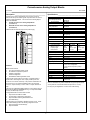
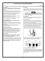
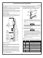
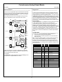
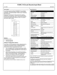
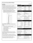
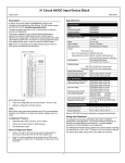
Current-source Analog Output Blocks
June 2002
GFK-0546D
Field Wiring ___________________________________
Removing an Electronics Assembly ______________
Terminals 5 to 32 are for field devices. They take a single wire up to
AWG #14 (avg 2.1mm2 in cross-section). Minimum recommended
size is AWG #20 (avg .54mm2 in cross-section).
The block’s Electronics Assembly can be replaced with a compatible
model without removing field wiring or reconfiguring the block.
Electronics
Assembly
The ground (GND) terminal (5) is for block safety. It is connected to
the block chassis, and to terminals 13, 16, 19, 22, 27, and 32 which
are marked GND. Each channel has one ground terminal for shield
termination, if desired.
Retaining
Screws
(Qty. 2)
Power Source Wiring
Connect an appropriate power source to terminals 6 and 7. For AC
block power, connect the source to the H terminal and neutral to the
N terminal. For DC block power, connect the source to the DC+
terminal and the return to the DC- terminal.
Terminal
Assembly
Connector
Pins
BSM
1.
Unscrew the retaining screws at the top and bottom of the block.
2.
Using a Block Puller (IC660BLM507), engage the tabs in the first
vent slots. Move the tool to the center of the block and squeeze the
handle.
3.
Pull the Electronics Assembly upward.
Warning
4-20mA
Current
Application
0-850 Ohm
Load
0-5V Voltage
Application
0-10 mA
Load
0-20V max.
Voltage Application
0-10 mA
Load
*
19
20
21
22
23
24
25
26
27
28
29
30
31
32
GND
H or DC+
N or DCNC
+BSM
-BSM
IOUT
RTN
GND
IOUT
RTN
GND
IOUT
RTN
GND
IOUT
RTN
GND
VOUT
IOUT
RTN
JMP
GND
VOUT
IOUT
RTN
JMP
GND
Inserting an Electronics Assembly
OUT 1
5
6
7
8
9
10
11
12
13
14
15
16
17
18
Power
If power is applied to the field terminals, power is also exposed
on the connector pins at the base of the Terminal Assembly,
and electrical shock hazard exists. Do not touch the connector
pins! Death or injury may result.
1.
Align the Electronics Assembly in the guides and push down firmly.
Caution
Do not exert excessive force; it may damage the block.
2.
If unusual resistance is met, remove the Electronics Assembly. If
power is applied to the block, DO NOT TOUCH THE CONNECTOR
PINS! Inspect the Terminal Assembly, connector receptacle, and
connector edge board (on the Electronics Assembly). Be sure the
keying matches. Remove any obstacles and reinsert the
Electronics Assembly. Pay close attention to the alignment of the
guide pins.
3.
Secure the Electronics Assembly with the screws on the top and
bottom of the Terminal Assembly.
LEDs _________________________________________
The block's Unit OK and I/O Enabled LEDs show its operating status.
Unit OK I/O Enabled
* User-Specified Resistor: 1K Ohm Maximum
Wiring for I/O Devices
Wiring for Current Outputs: If the load requires current in the 4 to
20mA range, connect it between the IOUT and RTN terminals (for
circuits 1 through 6).
Wiring for Voltage Outputs: If the load requires 0 to 5 volts power,
connect the load across the VOUT and RTN terminals (circuits 5
and 6 only). Attach a jumper across the RTN and JMP terminals.
If the load requires a different voltage range, connect it across the
VOUT and RTN terminals. Do not jumper the RTN and JMP
terminals. Instead, install an appropriate resistor across the IOUT
and RTN terminals. For example, the maximum voltage obtainable
if a 500 ohm resistor is used is:
VMAX = 20mA * 500 Ohms = 10V
3
Meaning
ON
ON
Block functioning, CPU communicating
ON
OFF
Block functioning
No CPU communications for 3 bus scans
ON
Blinking
Block functioning, Circuit forced
Blinking ON
Circuit fault, CPU communicating
Blinking OFF
Circuit fault
No CPU communications for 3 bus scans
Alternate Blinking
Circuit fault, Circuit forced
Synchronous
Blinking
No CPU communications - block number
conflict
OFF
Blinking
Electronics/Terminal Assembly mismatch
OFF
OFF
No block power, or block faulty