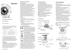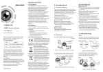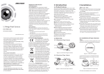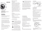
1
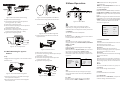
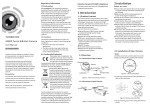
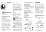
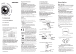
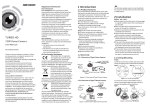
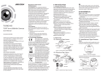
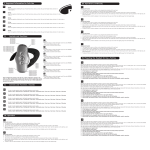
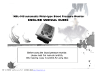
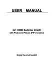
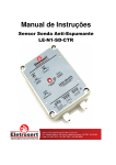
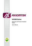
Regulatory Information
FCC Information
FCC compliance: This equipment has been
tested and found to comply with the limits for a
digital device, pursuant to part 15 of the FCC
Rules. These limits are designed to provide
reasonable protection against harmful
interference when the equipment is operated in
a commercial environment. This equipment
generates, uses, and can radiate radio
frequency energy and, if not installed and used
in accordance with the instruction manual, may
cause harmful interference to radio
communications. Operation of this equipment in
a residential area is likely to cause harmful
interference in which case the user will be
required to correct the interference at his own
expense.
TURBO HD
User Manual
UD.6L0201D1935A01
Thank you for purchasing our product. If there
are any questions, or requests, please do not
hesitate to contact the dealer.
This manual applies to
Model
Type I
DS-2CE16D1T-IR
TypeII
DS-2CE16D1T-IT1
Type III
DS-2CE16D1T-IT3
DS-2CE16D1T-IT5
This manual may contain several technical
incorrect places or printing errors, and the
content is subject to change without notice.
The updates will be added to the new version of
this manual. We will readily improve or update
the products or procedures described in the
manual.
Privacy Notice
Surveillance laws vary by jurisdiction. Check
all relevant laws in your jurisdiction before using
this product for surveillance purposes to ensure
that your use of this product conforms.
Please refer to the product specification for
camera parameters and functions.
0100001050409
Before you start:
1.1 Product Features
This series of camera adopts new generation
sensor with high sensitivity and advanced circuit
design technology . It features high resolution,
low image distortion and low noise, etc . , which
makes it suitable for surveillance system and
image processing system.
lHigh performance CMOS sensor and high
resolution bring high-quality image;
lLow illumination;
lOSD menu, parameters are configurable;
lSupport auto white balance, auto gain control,
electronic shutter control;
lSupport image effect adjustment;
lUnit transmission control;
lAdvanced 3-axis design meets different
installation requirements.
FCC Conditions
TVI Bullet Camera
Type
2 Installation
1 Introduction
This device complies with part 15 of the FCC
Rules. Operation is subject to the following two
conditions:
1. This device may not cause harmful
interference.
2. This device must accept any interference
received, including interference that may
cause undesired operation.
1.2 Overview
Mounting Base
HD Video Cable
Power Cable
Sun Shield
Lens
IR LED
2.1 Ceiling Mounting for Type I
Type II /Camera
Steps:
1.2.2 Overview of Type IICamera
HD Video Cable
Power Cable
1.Drill the screw holes in the ceiling according
to the supplied drill template.
2.Hammer the supplied plastic expansion bolt into
the screw holes.
Mounting Base
municipal waste in the European
Union. For proper recycling, return
this product to your local supplier
upon the purchase of equivalent new equipment,
or dispose of it at designated collection points.
For more information see: www.recyclethis.info.
2006/66/EC (battery directive):
This product contains a battery that
cannot be disposed of as unsorted
municipal waste in the European
Union.
See the product documentation for specific
battery information. The battery is marked with
this symbol, which may include lettering to
indicate cadmium (Cd), lead (Pb), or mercury (Hg).
For proper recycling, return the battery to your
supplier or to a designated collection point. For
more information see: www.recyclethis.info.
is in good condition and all the assembly parts
are included.
lMake sure that all the related equipment is
power-off during the installation.
lCheck the specification of the products for the
installation environment.
lCheck whether the power supply is matched
with your power output to avoid damage.
lPlease make sure the wall is strong enough to
withstand three times the weight of the camera
and the mounting.
lIf the wall is the cement wall, you need to insert
expansion screws before you install the camera.
If the wall is the wooden wall, you can use
self-tapping screw to secure the camera.
lIf the product does not function properly,
please contact your dealer or the nearest
service center. Do not disassemble the camera
for repair or maintenance by yourself.
1.2.1 Overview of Type I Camera
EU Conformity Statement
This product and - if applicable - the
supplied accessories too are marked
with "CE" and comply therefore with
the applicable harmonized European
standards listed under the Low Voltage Directive
2006/95/EC, the EMC Directive 2004/108/EC,
the RoHS Directive 2011/65/EU.
2012/19/EU (WEEE directive):
Products marked with this symbol
cannot be disposed of as unsorted
lPlease make sure that the device in the package
Sun Shield
Lens
All Screw Holes: for
mounting base
1.2.3 Overview of Type III Camera
Sun Shield
Power Cable
Figure 2-1 Drill Template
Lens
HD Video Cable
3.Route the cables to the cable hole and connect
the corresponding power cable and video cable.
4.Fix the camera to the ceiling with the supplied
screws.
3 Menu Operation
AWB: white balance is being adjusted
automatically.
MWB : Set the R GAIN/B GAIN value from 1 to 10.
As shown in Figure 3-3.
Type II
Type I
DAY/NIGHT
VIDEO
SETTING
BRIGHTNESS
MODE
CONTRAST
EXPOSURE MODE
INFRARED
SHARPNESS
AGC
SMART IR
SATURATION
AE
Figure 2-2 Fix the Camera to the Ceiling
5.Adjust the surveillance angle.
1).Loosen No.3 adjusting screw to adjust the
panning position ( 0° ~ 360° ).
2).Tighten No.3 adjusting screw .
3).Loosen the No.2 adjusting screw to adjust the
tilting position ( 0° ~ 90° ).
4).Tighten No.2 adjusting screw.
5).Loosen No.1 adjusting screw to adjust the
azimuth angle of the image ( 0° ~ 360° ).
6).Tighten No.1 adjusting screw .
Figure 2-5 Drill Template & Install Mount
SAVE/EXIT
DNR
Figure 3-1 Main Menu
Mounting Plate
DAY/NIGHT
With a coaxial camera controller (purchase
separately) or calling the preset No.95 you can
select the menu and adjust the camera parameters.
Figure 2-6 Screw the Mounting Plate
Figure 2-7 Fix the Camera
Steps:
EXIT
4. Screw the mounting plate onto the camera.
Figure 2-3 3-axis Adjustment
1.Wiggle the mounting plate to disassemble it from
the wall mount.
RESET
MIRROR
5. Fix the camera to the wall mount with the
supplied screws.
2.2 Wall Mounting for Type III
Camera
WB
5. Adjust the surveillance angle.
1). Loosen No.1 adjusting screw to adjust the pan
position (0° ~ 360°).
2).Tighten No.1 adjusting screw.
3). Loosen No.2 adjusting screw to adjust the
tilting position(0° ~ 90°).
4).Tighten No.2 adjusting screw.
Mounting Plate
3.1 FORMAT
You can set the format as PAL/NTSC.
3.2 SET UP
Move the cursor to SET UP , and press menu button
to enter the SET UP sub menu.
3.2.1 AE
Move the cursor to AE, and you can adjust the
image brightness by the BRIGHTNESS , EXPOSURE
MODE , and AGC .
Brightness :
Brightness refers to the brightness of the image.
Exposure Mode:
Move the cursor to Exposure Mode , you can select
the exposure mode between Globe and BLC .
When BLC is selected as the exposure mode, the
level of BLC mode can be adjusted, as shown in the
Figure 3-2.
EXPOSURE
1.BRIGHTNESS
2.EXPOSURE MODE
LEVEL
3.AGC
4.RETURN
WB
5
BLC
5
MIDDLE
MODE
R GIAN
B GAIN
RETURN
2
1.Drill the screw holes on the wall according to
the supplied drill template.
2.Attach the wall mount to the wall and tighten
the screws to fix it.
360°
1
MODE
MWB
1-|--10
1-|--10
8
Figure 3-2 EXPOSURE
AGC:
AGC optimizes the clarity of image in poor light
scene. AGC level can be set as OFF, LOW, MIDDLE
and HIGH.
Figure 2-8 Angle Adjustment
3.2.2 WB
Move the cursor to WB, and you can set White
Balance mode as AWB and MWB in this menu .
SMART
INFRARED
OFF
SMART IR
0-|--5
RETURN
Figure 3-3 WB
90°
Figure 2-4 Disassemble Mounting Plate
3.2.3 DAY & NIGHT
Move the cursor to DAY & NIGHT, and select
COLOR , B/W , or SMART as the DAY & NIGHT mode.
COLOR: The image is colored in day mode all the
time.
B/W : The image is black & white all the time, and
the IR LED turns on in the low-light conditions.
SMART : Select to turn on/off the INFRARED_LAMP
and to set the Smart IR level from 1to 16.
As shown in Figure 3-4.
8
Figure 3-4 DAY/NIGHT
3.2.4 VIDEO SETTING
Contrast:
Contrast enhances the difference in color and light
between parts of an image.
You can set the value from 1 to 10 .
Sharpness:
Sharpness determines the amount of
detail that an imaging system can reproduce.
You can set the value from 1 to 10.
Saturation:
You can set the saturation level of the image. The
value is from 0 to 10.
DNR:
DNR decreases the noise effect, especially in low
light conditions and delivers more accurate and
sharp image quality. You can set the value from
0 to 7.
Mirror :
You can set the Mirror status as H, V, HV, or OFF.
3.2.5 Reset
Reset all the settings to the default.
3.2.6 EXIT
Exit and Save & exit are selectable.
3.2.7 SAVE/EXIT
Move the cursor to SAVE & Exit , and press OK to
save the settings and exit the menu.