1
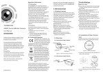
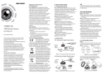
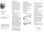
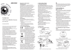
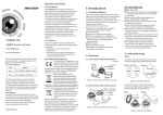
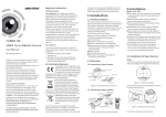
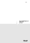
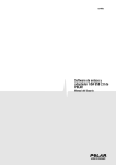
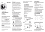
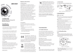
Regulatory Information
FCC Information
1.3 Mega Pixel Camera
User Manual
UD.6L0201D1282A01
www.hikvision.com
Thank you for purchasing our product. If there
are any questions, or requests, please do not
hesitate to contact the dealer.
This manual applies to DS-2CE15F5P(N)-VFIR 3 ,
DS-2CE55F5P(N)-VFIR3.
This manual may contain several technical
incorrect places or printing errors, and the
content is subject to change without notice.
The updates will be added to the new version of
this manual. We will readily improve or update
the products or procedures described in the
manual.
DISCLAIMER STATEMENT
Underwriters Laboratories Inc. (”UL” ) has not
tested the performance or reliability of the
security or signaling aspects of this product.
UL has only tested for fire, shock or casualty
hazards as outlined in Ul’s Standard(s) for Safety,
UL60950-1. UL Certification does not cover the
performance or reliability of the security or
signaling aspects of this product. UL MAKES NO
REPRESENTATIONS, WARRANTIES OR
CERTIFICATIONS WHATSOEVER REGARDING
0100001031213
THE PERFORMANCE OR RELIABILITY OF ANY
SECURITY OR SIGNALING RELATED FUNCTIONS
OF THIS PRODUCT.
1 Introduction
2 Installation
1.1 Product Features
FCC compliance: This equipment has been
tested and found to comply with the limits for a
digital device, pursuant to part 15 of the FCC
Rules. These limits are designed to provide
reasonable protection against harmful
interference when the equipment is operated in
a commercial environment. This equipment
generates, uses, and can radiate radio
frequency energy and, if not installed and used
in accordance with the instruction manual, may
cause harmful interference to radio
communications. Operation of this equipment in
a residential area is likely to cause harmful
interference in which case the user will be
required to correct the interference at his own
expense.
FCC Conditions
This device complies with part 15 of the FCC
Rules. Operation is subject to the following two
conditions:
1. This device may not cause harmful
interference.
2. This device must accept any interference
received, including interference that may
cause undesired operation.
This camera adopts new generation sensor with
high sensitivity and advanced circuit board design
technology. It possesses the features of high
resolution, low distortion, and low noise, etc. It is
extremely suitable for supervisory system and
image processing system.
The main features are as follows:
lHigh performance CMOS sensor and high
resolution bring high-quality image;
lLow illumination, 0.01 Lux @ (F1.2, AGC ON),
0 Lux with IR;
lSupport IR cut filter with auto switch;
lOSD menu, parameters are configurable;
lSupport auto white balance, auto gain control,
electronic shutter control and internal
synchronization;
lAdvanced Engineering Design and patent
universal adjustable structure provides
convenient adjustment and high reliability;
lSMART IR mode;
lUnit transmission control;
lAdvanced 3-axis design meets different
installation requirements;
lIngress protection: IP66.
EU Conformity Statement
1.2 Overview
This product and - if applicable the supplied accessories too are
marked with "CE" and comply
therefore with the applicable harmonized
European standards listed under the Low Voltage
Directive 2006/95/EC, the EMC Directive 2004/
108/EC, the RoHS Directive 2011/65/EU.
2012/19/EC (WEEE directive):
Products marked with this symbol
cannot be disposed of as unsorted
municipal waste in the European
Union. For proper recycling, return
this product to your local supplier
upon the purchase of equivalent new equipment,
or dispose of it at designated collection points.
For more information see:www.recyclethis.info.
2006/66/EC (battery directive):
This product contains a battery
that cannot be disposed of as
unsorted municipal waste in the
European Union.
See the product documentation for specific
battery information. The battery is marked with
this symbol, which may include lettering to
indicate cadmium (Cd), lead (Pb), or mercury (Hg).
For proper recycling, return the battery to your
supplier or to a designated collection point. For
more information see:www.recyclethis.info.
Before you start:
lPlease make sure that the device in the package
is in good condition and all the assembly parts
are included.
lMake sure that all the related equipment is
power-off during the installation.
lCheck the specification of the products for the
installation environment.
lCheck whether the power supply is matched
with your power output to avoid damage.
lPlease make sure the wall is strong enough to
withstand three times the weight of the camera
and the mounting.
lIf the wall is the cement wall, you need to insert
expansion screws before you install the camera.
If the wall is the wooden wall, you can use
self-tapping screw to secure the camera.
lIf the product does not function properly,
please contact your dealer or the nearest
service center. Do not disassemble the camera
for repair or maintenance by yourself.
2.1 Installation of Type I Camera
Steps:
1.2.1 Overview of Type I Camera
1.Drill the screw holes and the cable hole on the
ceiling according to the supplied drill template.
Camera
Enclosure
Zoom & Focus
Lock Screw
Video Cable
Trim Ring
Power Cable
Figure 1-1 Overview of Type I Camera
1.2.2 Overview of Type Camera
Mounting Base
Figure 2-1 The Drill Template
2 .Loosen the lock screw and release the clip
plate to disassemble the camera from the
mounting base.
Video Cable
Power Cable
Sun Shield
Main Body
Lens
IR LED
Focus
Zoom
Adjusting Sheet
Figure 1-2 Overview of Type II Camera
Clip Plate
Figure 2-2 Release The Lock Screw
3.Fix the mounting base to the ceiling.
4.Route the cables to the cable hole and connect
the corresponding cables.
5.Secure the camera to the mounting base by
tightening the lock screw.
6.Adjust the camera according to the figure below
to get an optimum angle.
5. Loosen the T screw, R screw and P screw
successively and adjust the camera according to
the figure below to get an optimum angle. Tighten
the screw after completing the adjustment.
R Screw
T Screw
0 ~360
P Screw
Figure 2-7 3-axis Adjustment
0 ~360
6.Adjust the Zoom Screw and Focus Screw till you
get the optimum surveillance angle.
7.Use the screwdriver to adjust the ZOOM screw
and the FOCUS screw until you get the optimum
image.
Figure 2-4 Zoom and Focus Adjustment
Steps:
Figure 2-8 Zoom and Focus Adjustment
AE
DAY
&NIGHT
WB
VIDEO
SETTING
FUNCTION
CONTRAST
DETECTION
AUTO
COLOR
SHARPNESS
MASKING
AGC
MANUAL
B/W
COLOR
GAIN
ZOOM IN
SMART
3D NR
LANGUAGE
RESET
SAVE
&EXIT
MIRROR
Figure 3-1 Main Menu
A coaxial camera controller (purchase separately)
is required to select the menu and adjust the
camera parameters.
3.1 AE
Move the cursor to AE, and you can adjust the
image brightness by the BRIGHTNESS , AE MODE ,
AGC , and SENS-UP in this menu.
As shown in Figure 3-2.
4.Connect the corresponding cables.
Move the cursor to WB, and you can set White
Balance mode as AUTO and MANUAL in this menu .
AUTO: white balance is being adjusted
automatically.
MANUAL : Set the R GAIN/B GAIN value
from 1 to 10. As shown in Figure 3-3.
Move the cursor to DAY & NIGHT, and select
COLOR , B/W , or SMART as the DAY & NIGHT mode.
COLOR: The image is colored in day mode all the
time.
B/W : The image is black & white all the time, and
the IR LED turns on in the low-light conditions.
SMART : Select to turn on/off the INFRARED_LAMP
and to set the Smart IR level from 0 to 5.
As shown in Figure 3-4.
1. INFRARED_LAMP
AE MODE
SENSE UP
Figure 2-6 Secure the Camera to the Ceiling
Figure 3-3 Manual of WB
SAMRT
Setup
BRIGHTNESS
2.Route the corresponding cables.
3.Secure the camera to the ceiling with the selftapping Screws .
Figure 3-2 AE
3 Menu Operation
1. Drill the screws holes on the ceiling according
to the supplied drill template.
Figure 2-5 The Drill Template
MANUAL
1. R GIAN
1-|--10
2. B GAIN
1-|--10
3. RETURN
8
BRIGHTNESS: Set the brightness value from
1 to 10 to darken or brighten the image.
AE MODE : Set AE mode as GLOBLE AE, and
D-WDR.
3.5 FUNCTION
You can set DETECTION , MASKING , ZOOM IN and
LANGUAGE of the camera in this menu.
FUNCTION
8
1. DETECTION
2. MASKING
8
3. ZOOM IN
50-|--100
4. LANGUAGE
ENGLISH
8
5. RETURN
Figure 3-6 Function
DETECTION: Set the motion sensitivity as
WEAK , LOW , MIDDLE or HIGH . Select an AREA to
enter the motion detection AREA menu. As shown
in Figure 3-7.
AREA : Set the status as OFF / ON . Select a color for
area border. Move the joystick up/down and right
/left to set the horizon/vertical size and position.
As shown in Figure 3-8.
3.3 DAY & NIGHT
Focus
Zoom
2.2 Installation of Type II Camera
AE
1. BRIGHTNESS 1-|--10
2. AE MODE
DWDR
3. AGC
OFF
4. SENSE UP
0-|---16
5. RETURN
8
3.2 WB
0 ~75
Figure 2-3 3-axis Adjustment
AGC : HIGH , MIDDLE , and LOW can be set for the
AGC level. Select OFF to disable the AGC.
SENSE UP : Set the SENSE UP value as 0, 2, 4, 8, 10,
12, 14 and 16.
OFF
2. SMART IR
0-|--5
3. RETURN
8
Figure 3-4 Smart Mode of DAY&NIGHT
3.4 Video Setting
Move the cursor to the VIDEO SETTING, and press
the menu button to enter the video configuration
interface. As shown in Figure 3-5.
SCREEN RATIO: Set the screen ratio as 4:3/16:9.
CONTRAST: Set the CONTRAST value from 1 to 10.
SHARPNESS : Set the edge and detail sharpness
value from 1 to 10.
COLOR GAIN: Set the color gain from 1 to 10.
3D NR : Set the 3D NR level as High , Middle ,
and Low . Select OFF to disable the 3D NR.
MIRROR : Set the mirror mode as OFF , H ,
V , or HV .
VIDEO SETTING
1. SCREEN RATIO
4:3
2. CONTRAST
1-|--10
8
2. SHARPNESS
3. COLOR GAIN
1-|--10
4. 3D NR
OFF
5. MIRROR
OFF
8
6. RETURN
Figure 3-5 Video Settings
DETECTION
1. SENSITIVITY HIGH
2. AREA NO.0
8
3. AREA NO.1
8
4. AREA NO.2
8
5. AREA NO.3
8
6. RETURN
8
AREA
1. STATUS
OFF
2. COLOR
WHITE
3. HORIZON SIZE
0
4. VERTICAL SIZE
0
5. HORIZON MOVE
0
6. VERTICAL MOVE
0
7. RETURN
8
Figure 3-7 Detection Figure 3-8 Detection Area
MASKING: Select a masking back ground color.
Select an AREA to enter the masking AREA menu.
As shown in figure 3-9.
AREA : Set the status as OFF / ON . Move the joystick
up/down and right/left to set the horizon/vertical
size and position.
As shown in Figure 3-10.
MASKING
1. COLOR
WHITE
2. AREA NO.0
8
3. AREA NO.1
8
4. AREA NO.2
8
5. AREA NO.3
8
6. AREA NO.
8
7. AREA NO.5
8
8. AREA NO.6
8
9. AREA NO.7
8
10.RETURN
8
AREA
1. STATUS
OFF
2. HORIZON SIZE
0
3. VERTICAL SIZE
0
4. HORIZON MOVE 0
5. VERTICAL MOVE 0
6. RETURN
8
Figure 3-10 Masking
Figure 3-9 Marsking Area
ZOOM IN : The ZOOM IN value can be adjusted from
50 to 100.
LANGUAGE: Chinese and English are selectable.
3.6 Reset
Reset all the settings to the default.
3.7 Save & Exit
Move the cursor to SAVE & RESET , and press OK to
save the settings and exit the menu.