1
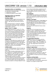
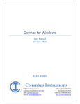
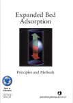
UNICORN 5.0N
UNICORN Validation Support Package
for
UNICORN 5.0N
04-0021-58
Edition AB / January 2004
UNICORN 5.0N
TABLE OF CONTENTS
1.
INTRODUCTION TO THIS DOCUMENT ........................................................................... 1
2.
INTRODUCTION TO UNICORN VALIDATION................................................................ 1
2.1.
2.2.
2.3.
GENERAL UNICORN INFORMATION .......................................................................................... 1
VERSION NUMBERING ............................................................................................................... 3
INDEPENDENT UNICORN AUDITS ............................................................................................. 4
3.
AMERSHAM BIOSCIENCES QUALITY MANAGEMENT SYSTEM ................................. 7
3.1.
3.2.
3.3.
INTRODUCTION ........................................................................................................................ 7
PROTEIN SEPARATIONS QUALITY POLICY ................................................................................... 7
ISO CERTIFICATION ................................................................................................................. 7
4.
PRODUCT DEVELOPMENT ............................................................................................... 9
4.1.
4.2.
4.3.
4.4.
INTRODUCTION ........................................................................................................................ 9
DEVELOPMENT MODEL ............................................................................................................. 9
SERVICE, MAINTENANCE AND SPAREPARTS .............................................................................. 13
ERROR REPORTING ................................................................................................................. 13
5.
COMPUTERIZED SYSTEM VALIDATION ...................................................................... 14
5.1.
5.2.
5.2.1.
5.2.2.
5.3.
5.3.1.
5.3.2.
5.3.3.
5.3.4.
5.3.5.
5.3.6.
5.3.7.
5.4.
5.4.1.
5.4.2.
5.4.3.
5.4.4.
5.5.
5.5.1.
5.5.2.
5.5.3.
5.5.4.
5.6.
5.6.1.
5.6.2.
5.6.3.
5.6.4.
5.6.5.
5.6.6.
5.6.7.
INTRODUCTION ...................................................................................................................... 14
DESIGN & SPECIFICATION PHASE ............................................................................................. 14
Functional Requirements .................................................................................................... 14
System Specification .......................................................................................................... 14
HARDWARE INSTALLATION & QUALIFICATION PHASE ............................................................... 14
System Description with Schematic Drawings...................................................................... 14
Piping & Instrument Drawing ............................................................................................. 14
Instrument List .................................................................................................................. 15
Input/Output List ............................................................................................................... 15
Wiring Checks................................................................................................................... 15
Component Qualification.................................................................................................... 15
Calibration ........................................................................................................................ 15
SOFTWARE DEVELOPMENT / VERIFICATION PHASE .................................................................... 15
Quality Assurance Methods for Software Development......................................................... 15
Process Operating Logic..................................................................................................... 15
Program Description (Application Code) ............................................................................. 16
Software Structural Description........................................................................................... 16
SYSTEM INTEGRATION AND VERIFICATION PHASE ..................................................................... 16
Module Level Verification.................................................................................................. 16
Program Level Verification................................................................................................. 16
System Level Verification .................................................................................................. 17
Additional Software Verification Requirements.................................................................... 17
OPERATIONAL PHASE ............................................................................................................. 17
Change Control.................................................................................................................. 17
System Recovery Plan........................................................................................................ 17
Operating Manuals............................................................................................................. 18
Training of Personnel ......................................................................................................... 18
Support Personnel .............................................................................................................. 18
System Security ................................................................................................................. 18
Operating Procedures ......................................................................................................... 18
Edition AB / January 2004
UNICORN 5.0N
6.
VALIDATION OF A UNICORN BASED CHROMATOGRAPHY SYSTEM...................... 19
6.1.
6.2.
6.2.1.
6.2.2.
6.2.3.
6.3.
6.4.
6.5.
6.5.1.
6.5.2.
6.5.3.
6.5.4.
6.5.5.
6.5.6.
6.5.7.
6.5.8.
6.6.
6.6.1.
6.6.2.
6.7.
6.8.
6.8.1.
6.8.2.
6.9.
INTRODUCTION ...................................................................................................................... 19
DESIGN, VALIDATION PLAN AND ACTIVITY SCHEDULE .............................................................. 21
Design and Requirements analysis....................................................................................... 21
Validation Plan .................................................................................................................. 21
Activity Schedule............................................................................................................... 21
INSTALLATION QUALIFICATION (IQ) ........................................................................................ 26
OPERATIONAL QUALIFICATION (OQ) ....................................................................................... 26
METHOD DEVELOPMENT AND VERIFICATION ............................................................................ 26
Product Specification ......................................................................................................... 27
Method Development Plan.................................................................................................. 28
Process Optimization.......................................................................................................... 28
Method Construction.......................................................................................................... 28
Backup / Restore................................................................................................................ 29
Verification ....................................................................................................................... 30
Operating Instructions ........................................................................................................ 30
Revalidation ...................................................................................................................... 30
EDUCATION ........................................................................................................................... 31
System education ............................................................................................................... 31
Method education .............................................................................................................. 32
VALIDATION APPROVAL ......................................................................................................... 32
VALIDATION OF PC-BASED NETWORKS .................................................................................... 32
Introduction....................................................................................................................... 32
Validation strategy ............................................................................................................. 32
INSTALLATION QUALIFICATION AND OPERATIONAL QUALIFICATION SERVICES FROM AMERSHAM
BIOSCIENCES FAST TRAK VALIDATION ..................................................................................... 34
7.
REFERENCES .................................................................................................................... 34
Edition AB / January 2004
UNICORN 5.0N
1.
INTRODUCTION TO THIS DOCUMENT
This support package is valid for all UNICORN™ versions 5.0N. The last (third) digit has been
replaced with a letter “N”. (see 2.2 in this document)
The document has been assembled to provide important information on the development and
documentation of UNICORN 5.0N. It will assure system owners that UNICORN has been
developed in a structured manner, and verified in accordance with the System Development Life
Cycle concept. The proper development, verification, and documentation are vital to the
functionality and performance of UNICORN when in operation at a customer’s site, and should,
accordingly be of interest to system owners.
This document gives an overview of how UNICORN is developed. It would have been desirable
to include all the documents created during the development of UNICORN 5.0N in this
information package, but this is not practical and realisable. Customers, who wish to verify the
existence of the documentation and development procedures, may perform audits in Uppsala
and/or in Umeå, Sweden.
This document provides a comprehensive description of the validation of the UNICORN system
that controls ÄKTA™, BioProcess™, OligoPilot™, and OligoProcess™ systems. It also suggests
a validation order and documentation that may be generated through the different steps in the
validation procedure. Installation Qualification and Operational Qualification services available
through Amersham Biosciences Fast Trak Validation are described in section 6.9.
A standardised source-code escrow agreement for UNICORN can be ordered through Amersham
Biosciences Fast Trak Validation.
2.
2.1.
INTRODUCTION TO UNICORN VALIDATION
General UNICORN information
Amersham Biosciences UNICORN system affords state-of-the-art control over Amersham
Biosciences chromatography systems, providing a level of sophistication and refinement not
available in other competitive chromatography control systems.
The configurable nature of UNICORN allows considerable variation in systems to meet the
requirements of an individual customer. These activities involve the participation of both
Amersham Biosciences and the system’s owner from the start of the purchasing activity through
system start-up at the owner's location.
Each UNICORN system is delivered with the same software, but many of its capabilities can only
be accessed if the particular system itself is equipped for that specific function. The sophistication
of the software allows even the most complex chromatographic separations to be implemented
since they can be assembled from software components included with each UNICORN.
Amersham Biosciences has a unique knowledge how FPLC™, ÄKTA, BioPilot™, BioProcess,
OligoPilot and OligoProcess systems have been developed and verified. To system owners, this
knowledge and documentation should be of interest in the validation process, assuring that
Amersham Biosciences utilises procedures and documentation which complies with accepted
standards throughout the pharmaceutical industry.
Edition AB / January 2004
1
UNICORN 5.0N
The following picture, UNICORN validation, illustrates the relations between the system owner,
Amersham Biosciences and activities and documentation which should be involved in the
validation process for a UNICORN based chromatography system.
U N IC O R N V alidation
S ystem
O w ner
B M I
P r o te in
S e p a r a tio n s
U N IC O R N
System
D oc
M ethod
Installation
Documentation provided or available from Amersham Biosciences
Support available from Amersham Biosciences Fast Trak
S ystem O wners input or d ocum e ntation
BMI refers to the instructions and procedures used by Amersham Biosciences in the
development of the system. See Section 3 Amersham Biosciences Quality Management
System.
System Owner is the person at the users site who is responsible for the correct functioning
of the system.
UNICORN refers to the documentation produced during the development of UNICORN.
System Doc is the system-specific documentation supplied to the system owner from
fabrication and final testing of the individual system.
Installation refers to the Installation Qualification and Operational Qualification (IQ and
OQ) for the system. These document templates can be ordered separately from
Amersham Biosciences Fast Trak Validation by the customer, but are not a part of the
documentation delivered with the system.
Method refers to the customer’s method development and other relevant procedures (i.e.
education of users). These procedures are described in more detail in the Section
Validation of a UNICORN based Chromatography System.
Protein Separations is the knowledge and activities needed to optimize the process as the
choice of chemicals, media, product materials, buffers, etc.
Edition AB / January 2004
2
UNICORN 5.0N
2.2.
Version numbering
When UNICORN software is changed/modified, the numbering system is used to indicate which
degree of modification has been performed. The following text describes the principles used.
The version number used consists of 3 digits and is written X.YZ. Example: 4.12.
X – New version
• new operating system
• major new functionality
Y-Update
•
•
adaptations for new hardware components
minor new functionality
Z – Bug fix
• correction of software errors
• no new functionality; specifications not extended
• software manual not affected
Bug fixes are separate from updates, new functionality and new version releases.
When X is incremented, Y and Z are set to zero. When Y is incremented, Z is set to zero.
The following versions of UNICORN have been released from Amersham Biosciences (in
chronological order) :
UNICORN version
Released
Operating system
1.00
Dec. 1992
OS/2
1.01
Feb. 1993
OS/2
1.10
Sept. 1994
OS/2
1.11
Dec. 1994
OS/2
1.12
Feb. 1995
OS/2
2.00
Dec. 1995
OS/2
2.01
Feb. 1996
OS/2
2.10
Apr. 1996
OS/2
2.20
Oct. 1996
OS/2
2.30
Feb. 1997
OS/2
3.00
May 1998
Windows NT
2.33
May 1999
OS/2
3.10
May 1999
Windows NT
3.20
Nov. 1999
Windows NT
3.22
March 2001
Windows NT
4.00
May 2001
Windows NT/2000
4.11
June 2002
Windows NT/2000
4.12
July 2003
Windows NT/2000/XP
5.00
January 2004
Windows 2000/XP
Edition AB / January 2004
3
UNICORN 5.0N
OBSERVE !
Upgrading software in a system may have an impact on its functionality, and a
revalidation may be necessary. This should be evaluated prior to performing
any modification or upgrading of the software.
2.3.
Independent UNICORN Audits
Already when the first version of UNICORN was developed, an independent company, Weinberg
Associates Inc. audited the principles and procedures employed by Amersham Biosciences in the
development of UNICORN. As a result of this audit, Amersham Biosciences obtained a
certificate, which confirms that the development model complies with relevant regulatory
standards.
Compliance with the FDA 21 CFR Part 11 was obtained starting with UNICORN 3.2.
Certificate and audit report from UNICORN 5.0 is included in this support package.
Edition AB / January 2004
4
UNICORN 5.0N
Edition AB / January 2004
5
UNICORN 5.0N
Edition AB / January 2004
6
UNICORN 5.0N
3.
3.1.
AMERSHAM BIOSCIENCES QUALITY MANAGEMENT SYSTEM
Introduction
Amersham Biosciences´ quality management system, BMI (Business Management Information),
is based on a process and system approach as described in the Protein Separations Quality
Manual. It encompasses the steering structures and procedures needed to achieve the business
objectives.
3.2.
Protein Separations Quality Policy
The Quality System should support the strategy of Protein Separations by assuring quality through
active management of the following:
•
•
•
3.3.
Identification and documentation of customer needs.
Development, manufacturing and delivery of products and services to meet or exceed those
needs consistently.
Feedback from customer assessment leading to improvement in performance for Protein
Separations, minimising cost and complaints.
ISO Certification
ISO 9000 is an internationally accepted series of quality management standards. Certification
requires rigorous auditing by an independent accredited agency which examines the quality
documentation system and confirms that the organisation actually operates in accordance with
stipulated principles and instructions.
Amersham Biosciences first achieved ISO 9001 certification in February 1993. On September 26,
2003, the company received Certificate of Approval to the Quality Management System Standard
ISO 9001:2000 (see certificate below).
Edition AB / January 2004
7
UNICORN 5.0N
Edition AB / January 2004
8
UNICORN 5.0N
4.
4.1.
PRODUCT DEVELOPMENT
Introduction
Amersham Biosciences utilises structured and documented procedures to provide customers with
high quality products. To comply with this, customer expectation, opinions and other relevant
information are gathered together with Amersham Biosciences development principles and
technical modifications. These are considered when UNICORN software is developed.
Adherence to Amersham Biosciences procedures is verified throughout all phases of product
development.
4.2.
Development model
The procedure for product development defines the phases, main activities and responsibilities,
reviews and phase exits to be performed. This is visualised in the Figure “Development (D)
project”.
Edition AB / January 2004
9
UNICORN 5.0N
Edition AB / January 2004
10
UNICORN 5.0N
For software development, additional procedures are used. Figure “swBMI steps” shows the main
activities. These procedures also contain information regarding responsibilities, verification,
reviews and approval, error handling etc. Templates/forms are also available (see Figure
“Available templates”).
swBMI steps
Project planning
Sw project planning including test plans in SDP
Sw Analysis
Sw Design
Requirements in
SRS. Matching
test cases in STD
Design in SDD
(and model)
User interface in
HIS
Test cases for
module
integration in
ITD
Sw
Implementation
Approval for Use
Sw Integration
Implement and
test each module.
Test cases in MTD
Integrate the sw
modules
Documentation in
code, model or
MDD
Test ITD, STD
and SVP/SVR
non-internal versions
Approval for Use
(before phase 3 exit)
Versions of
used documents
and files in SVD
Code to source
code archive
Final SwQA audit
(before phase 5 exit)
Sw development handbook 70-5012-08
Available templates
Project planning
Sw Analysis
SDP
Co-operation routines
3rd part evaluation
Sw Development Plan
(optional)
(optional)
Sw Design
Sw Implementation
Sw Integration
HIS
SDD
MDD
ITR
sw Human Interface
Specification
Sw Design Description
sw Module Design
Description
sw Integration Test
Report
or documentation in
SDD, code, model
STR
IDD
sw System Test Report
sw Interface Design
Description (option)
SVP/SVR
SRS
Sw Requirement
Specification
MTD
CEV
sw Computer
Equipment Verification
description
sw Modulte Test
Description
sw Computer
Equipment Verification
report
ITD
MTR
sw System Test
Description
sw Integration Test
Description
sw Module Test
Report
sw QA audit report
sw Approval for
Use minutes
Sw Verification Plan
and Report
see 70-5000-13
CEV
STD
Approval for Use
non-internal versions
(Bug-list
implemented as
extract from
dbPlus)
SVD
Sw Version Description
Sw development handbook 70-5012-08, section Sw steps and documents
See BMI for document number of the templates
Edition AB / January 2004
11
UNICORN 5.0N
The output from the software development results in an executable, documented, verified and
archived software system.
Edition AB / January 2004
12
UNICORN 5.0N
The figure “Test descriptions and reports during Verification” summarises the verification
performed on the different levels, including the documents used to describe the test cases and the
test result.
T est d escrip tio n s an d rep o rts d u rin g V erificatio n
G A M P level
A d d itio n al v e rificatio n at cu sto m er site
S y stem v erificatio n
IQ , O Q , P Q
V erificatio n rep o rt
V erificatio n
V erificatio n rep o rt
sw test d e scrip tio n in S V P , 7 0 -5 0 0 0 -1 3
S ystem
In teg ration
D p ro c e d u re 7 0 -5 0 1 0 -0 5
S w a p p lica tio n S V P
S V R rep o rt
7 0 -5 0 0 0 -1 3
70 -5 0 0 0 -1 3
S w req u irem en t S T D
S T R rep o rt
S w in teg ratio n IT D
IT R rep o rt
S w m o d u le M T D
M T R rep o rt
In teg ration
M o dule
C ode
C ode
S w d e v elo p m e n t han d b o o k 7 0 -5 0 1 2 -0 8
4.3.
Service, Maintenance and Spare parts
Labcrew™, Amersham Biosciences instrument service group delivers the background technical
maintenance, expertise and service that keeps science running smoothly.
Each member of our service team has the capability to quickly assess a situation, identify
problems, and deliver rapid corrective measures on site. From preventative maintenance and
instrument repair to software and hardware upgrades, Labcrew keeps your equipment in peak
condition.
Spare parts can be ordered through your local Amersham Biosciences office. Most commonly
used parts are stored locally, and can be provided immediately. Your local office will also be
pleased to arrange delivery of specialist spare parts from our global distribution centres.
On call from our service centres worldwide, Labcrew’s mission is to keep your science on track
4.4.
Error Reporting
In order to ensure that correct actions are taken when an error is reported on a product, Amersham
Biosciences follows documented routines to ensure correct handling and feedback to customers at
all times.
Users shall always report product issues to the local Amersham Biosciences representative for
further action.
Edition AB / January 2004
13
UNICORN 5.0N
5.
COMPUTERIZED SYSTEM VALIDATION
5.1.
Introduction
The following text provides a brief description of each of the tasks necessary to complete the
validation effort. For comparison to the life cycle diagram in the PMA concept paper, the
requirements have been separated into major headings, which correspond to the major segments
of the PMA life cycle. The following list is not intended to be all-inclusive. Depending on the
application and sophistication of the system, the details of any individual system may be
significantly different from that described herein.
5.2.
Design & Specification Phase
This portion of the project establishes the groundwork for the entire effort.
5.2.1.
Functional Requirements
A description of the functions which the computerised system must provide. It defines the
scope of the hardware and software required to complete the project. It is essentially a
shopping list indicating the desired features of the completed system. It is sufficiently
detailed to establish the design while allowing for flexibility in the design at the same time.
5.2.2.
System Specification
A detailed compilation of the system as designed to meet the elements of the Functional
Requirements. It identifies specific hardware features (CPU, printers, CRTs, storage
devices, UPSs, and their overall arrangement) and an overview of software considerations
(report formats, levels of alarms, scan time, menus, etc.).
5.3.
Hardware Installation & Qualification Phase
This activity includes documentation and verification of the hardware required. Hardware
configuration / specifications for each device should be included. Vendor manuals for each piece
of hardware are required. Hardware qualification elements are outlined below.
5.3.1.
System Description with Schematic Drawings
A schematic representation of the entire system showing the major elements of the system.
It should include both process and control system components, as well as any other
computer systems with which the system communicates.
5.3.2.
Piping & Instrument Drawing
Schematic representation of the equipment in the field. There may be as many of these as
necessary to depict all of the process equipment. They are generally produced early in the
project.
Edition AB / January 2004
14
UNICORN 5.0N
5.3.3.
Instrument List
A listing of all instruments in the system, including their operating ranges, output signals,
selected manufacturer, proposed calibration frequency, accuracy, etc. Each instrument in
the list is uniquely identified and can also be found on the Piping & Instrument drawings.
5.3.4.
Input/Output List
A list of all signals and inputs received by the system as well as all outputs from the
system. Includes communications with other computer systems.
5.3.5.
Wiring Checks
Verification of the accuracy of cabling and connections to and from all field devices and
I/O racks. Also includes verification of cabling between items in the control system and
between the control system and other computer systems with which it must communicate.
5.3.6.
Component Qualification
Documentation that all physical components in the control system are installed in
accordance with the vendors recommendations. Includes the satisfactory completion of all
self-tests possible on each piece of equipment. To the extent that the computer system can
be tested without application software, that testing should be performed and documented.
Issues such as electrical grounding, isolation from power lines, protection from excessive
heat and humidity must be addressed.
5.3.7.
Calibration
Documented calibration of all field devices from the sensor to the control system. It
includes verification that all locations where a variable is stored, displayed or transmitted
are within the required tolerances. Includes the completion of SOPs for the routine
calibration of the instruments and the initial frequency with which they will be calibrated.
5.4.
Software Development / Verification Phase
Activities associated with the detailed design, preparation and verification of the software to be
utilized on the system.
5.4.1.
Quality Assurance Methods for Software Development
Copies of procedures utilized by the developers of the program (external and internal)
which indicate the software quality assurance measures which are to be followed in the
preparation of the code. Such measures include the use of modular concepts, consistent and
logical use of variable names, maintaining documentation on requested changes, etc.
5.4.2.
Process Operating Logic
Detailed descriptions of the various procedures to be carried out by the system. It is
developed by personnel knowledgeable in the pharmaceutical process for the purpose of
communicating process information to the programmer. It indicates the routine process, as
well as the desired response to likely process upsets, data entry errors, component failures,
etc. Logic flow diagrams are sometimes employed for this purpose.
Edition AB / January 2004
15
UNICORN 5.0N
5.4.3.
Program Description (Application Code)
Paper and/or electronic copies of the software that are to be validated. The annotation of
source code is highly desirable as a means of initial preparation, audit and subsequent
change. At this stage the software can be audited but it cannot be rigorously tested until it
is installed on the hardware.
5.4.4.
Software Structural Description
An overview of the software defining the various programs, including modules [and their
functions], their relationship to each other, any sub-routines and sub-programs. It
sometimes includes additional information such as protocol lists, batch sequences, alarm
points, etc. that are utilized.
5.5.
System Integration and Verification Phase
Once the hardware installation and software development is complete, the project enters the
integration and verification phase. Here the software and hardware are combined, and verification
of the combination is performed. Usually this verification is performed in a modular fashion, but
eventually all parts of the system must be placed into service. Verification reports are prepared for
all of the testing performed in this phase. The results of all the testing done at this phase are
included in a formal verification report.
5.5.1.
Module Level Verification
Testing of individual modules to demonstrate their adherence to the specifications.
Verification at this level consists of individual functions; e.g. alarms, report formats, screen
displays, data transmission. Testing of individual modules in a distributed control system is
an example of this type of verification.
5.5.2.
Program Level Verification
Program Level Verification is testing of individual programs to confirm their conformance
to specifications. Testing at this level is performed in one or more of the following ways.
Simulation
Simulation is the use of simulated inputs to the control system to confirm that the
computer system responds in the desired way to each input. The inputs should be
both in accordance with the routine process (uneventful - to confirm proper
sequence) or outside the norm (eventful - to confirm the appropriate response to
anticipated process or system upsets). The simulation trial confirms the
acceptability of the computer system. Simulation should be performed on every
module which will be utilised on the system.
Placebo Batching
Is the use of simulated product to confirm that the computerized system performs
in the desired manner. The placebo batches should be made both in accordance with
the routine process (uneventful - to confirm proper sequence) or outside the norm
(eventful - to confirm the appropriate response to anticipated process or system
upsets). The placebo batch confirms the acceptability of the computerized system.
Placebo batches should be made for every product to be made in the system. In
some instances it may be necessary to make both maximum and minimum placebos
to assure that process parameters, alarms, and sensor locations are appropriate for
all batch sizes. Placebo batching is also used for non-product operations such as
cleaning.
Edition AB / January 2004
16
UNICORN 5.0N
5.5.3.
System Level Verification
Verification of system performance under actual use is called System Level Verification.
This is performed at the user's site.
Product Batching
Batches of actual product are produced in the system using full automation. The
batches produced are subjected to full validation testing to ensure their conformance
to the required product specifications. No intentional upsets are introduced into the
process. The successful production of product establishes the suitability of the
system to make releasable material. Comparable verification is performed on other
automated activities managed by the control system to confirm their acceptability,
i.e., cleaning, data reduction, etc.
5.5.4.
Additional Software Verification Requirements
Additional testing is required to establish that other software features are correct and
function as desired. Examples of the types of additional software capabilities, which must
be validated include: verification of security measures, confirmation of communication
capabilities with other computer systems, verification of data archive systems, and protocol
management. In general, all the features and capabilities of the computerised system must
be validated.
5.6.
Operational Phase
The procedures and systems needed to ensure the acceptability of the system over time should be
inspected at the time of system start-up.
5.6.1.
Change Control
Change control procedures must be developed whereby changes in the process, process
equipment, software and computer hardware may be evaluated, approved and documented.
As necessary, additional qualification and/or validation may be needed to evaluate a
change. The procedure should allow for both planned and emergency changes to the
system. Emergency change methods are needed when situations requiring immediate
action to protect personnel, equipment or product are encountered. Change control
procedures must include provision for the updating of pertinent documentation on the
system including many of the elements of this document. Records of changes to the system
must be kept for the same period of time as any other regular production document.
5.6.2.
System Recovery Plan
Focuses on the data recovery and system restart procedures. For example, database
journaling may be used to keep track of all transaction operations that affect the values of
database items. A copy of the software, including essential files, should be kept off-line to
be used in disaster recovery. The system recovery plan should address all aspects of
recovery from loss of a hard-drive, corruption of a file, or loss of power to the system.
Procedures for returning the system to full and proper performance must be in place.
Provisions for safeguarding product and essential data must be defined. The validation of
these procedures is recommended.
Edition AB / January 2004
17
UNICORN 5.0N
5.6.3.
Operating Manuals
Operating manuals should be available to the users of the system at all necessary locations.
These manuals must be written at a level such that the actual operators can use them.
Verification of user manual correctness can be a concern for systems with many features.
5.6.4.
Training of Personnel
All users of the system must be trained on the various functions they will be performing.
All training should be documented.
5.6.5.
Support Personnel
A listing of support personnel and their responsibilities and qualifications should be
included as part of the documentation.
5.6.6.
System Security
The documentation should describe the physical (hardware) security employed to protect
the system, as well as software security. Verification of security measures is strongly
recommended.
5.6.7.
Operating Procedures
Standard operating procedures (SOPs) required for manual steps must be completed. These
procedures should include operations performed on a routine basis, as well as procedures
needed for occasional use, i.e. calibration preventative maintenance.
Edition AB / January 2004
18
UNICORN 5.0N
6.
6.1.
VALIDATION OF A UNICORN BASED CHROMATOGRAPHY SYSTEM
Introduction
Validation is a process in which the system owner (who is responsible for the system) performs
actions to determine that a system and process are consistently capable of producing a product
which meets its pre-determined specifications and quality attributes. These actions should involve
Design and Requirements analysis, Installation Qualification, Operation Qualification, Method
Development and Verification, Education, and other actions that the system owner finds relevant
in order to allow the system to start. The validation process should end with an approval from the
system owner of all previous activities, meaning that a high degree of assurance, which ensures
that the system is fit for its intended use, has been obtained. After the system owner has approved
the system to start production (or other intended activity), the system can be called validated. The
word “validated” does not specify any particular level of validation, it simply means that the
system owner has approved of its fitness for its intended use. Validation of a system should not be
performed simply to please authorities, but to obtain a system that operates as intended.
Regulations emphasise that the system should not produce harmful or sub quality products.
The following document contains a suggested validation strategy for UNICORN controlled
systems. Following the procedures explicitly will not give any guarantee that a system that
complies with official regulations is obtained. However, if the procedures suggested here are
performed, completed and modified as needed, a validated system can be obtained. We strongly
advise you to be well informed of the regulatory aspects that are related to your product and
process. From a regulatory point of view, the system owner is always responsible for the
performance of his/her system, and an established opinion of inspectors is that if written evidence
of an activity cannot be presented, the activity has not been performed. These recommendations
are mainly based on the U.S. FDA's Good Manufacturing Practice (GMP), since they are widely
accepted throughout the world.
Validation of UNICORN controlled systems can be performed according to the following
illustration (Figure Validation order).
Edition AB / January 2004
19
UNICORN 5.0N
Validation order
Design and Requirements Analysis
2.1
Validation Plan
2.2
Activity Schedule
2.3
3
Operation
Qualification
4
Method Development
and Verification
5
6 + 6.1
Method education
System education + general education
Installation
Qualification
6.2
Validation Approval
7
The figure “Validation order” illustrates that validation is a process with components, and not just
a task that has to be carried out before a system is put into production.
Edition AB / January 2004
20
UNICORN 5.0N
6.2.
6.2.1.
Design, Validation Plan and Activity Schedule
Design and Requirements analysis
System design is vital to its function. Amersham Biosciences provides design assistance to
its customers and most systems delivered are designed in accordance with customer
demands.
The design phase should not only involve the construction of the chromatography unit, but
also take into consideration the intended use of the system. The intended use will dictate
the required level of validation. For example, the requirement for production of a
therapeutic product is quite stringent.
6.2.2.
Validation Plan
A Validation Plan should include all components required to obtain the desired validation
level. The plan and specified activities are fundamental in the validation of the system, and
should be approved by the system owner.
The Validation Plan should include all tests and verifications needed to obtain the desired
validation level. This includes not only items mentioned here, but also other relevant
activities, e.g., supplier audits. The earlier chapters of this documentation describe the
development instructions and procedures Amersham Biosciences uses to develop and
supply UNICORN. This information is part of a validation procedure of UNICORN
controlled systems, and can be included in the owners validation documentation.
As mentioned earlier, tests of the system during its operation will almost certainly not be
all inclusive. This implies that the design of a system is of great importance.
6.2.3.
Activity Schedule
From the Validation Plan, an Activity Schedule can be extracted, specifying each activity
and responsible person(s). The activity schedule can be constructed in different ways, but it
is important to recognise what activities must precede others. A few activities, however,
can be performed independently of others (e.g., system and general education).
General education is dependent mainly on two factors: that the personnel involved in the
development and the handling of the system should have been selected, and the education
should be performed prior to use of the system in production.
System education can be divided in two major parts: system specific education and
handling education, the latter being dependent on the existence of an operative system.
System specific education can be performed during the IQ and OQ of the system.
The following figure illustrates an example of an Activity Schedule with sub-levels,
describing the development of a backup system.
Edition AB / January 2004
21
UNICORN 5.0N
Activity Schedule
Edition AB / January 2004
22
UNICORN 5.0N
Edition AB / January 2004
23
UNICORN 5.0N
Activity
Responsible
Target
date
Activity 1
P. Person
2003-12-10
Activity 2
B. Berg
2003-12-15
Backup
G. Gren
Finished
date
2003-12-08
Signature
2003-12-24
Activity 4
S. Stenson 2003-12-31
Activity N
O. Olsson 200N-NN-NN
Activity N
N.N.
200N-NN-NN
select technique
purchase of equipment
Activity 1
Activity Scedule
Activity
Activity 1
Activity 2
Backup
Responsible
Target
date
Finished
date
Signature
install HW +SW
Activity 2
P. Person 2003-12-10 2003-12-08
P. Berg
G. Gren
2003-12-15
select procedure & routines
2003-12-24
Activity 4
S. Stenson 2003-12-31
Activity N
O. Olsson 200N-NN-NN
Activity N
N.N.
Backup
200N-NN-NN
test of back-up
Activity 4
SOP's
Activity N
desc. BU+ Restore
handling/security SOP's
The Activity Schedule should in this case contain information describing who is
responsible for the development of a backup procedure and a date when this activity should
be finished. It should also refer to the “Backup”-activity document (below), in which more
detailed information can be found.
The “Backup”-activity document should describe the specific steps (and
responsible persons for these), needed to obtain a complete and documented routine.
It should also include an official approval, when completed, from the person
responsible for the “Backup”-activity.
Edition AB / January 2004
24
UNICORN 5.0N
“Select technique” as a suggested first step, would be to determine which
different backup techniques are available, and which one of these is
preferable, considering security, volume, economic, technical aspects and the
effects of a loss of data. These considerations should of course be made in
conjunction with the system owners’ expectations of the system.
Suggested documentation: A document describing the investigation
considering all aspects involved.
“Purchase of equipment”, refers to the ordering and delivery of the
necessary hard- and software.
Suggested documentation: Notes concerning which equipment was ordered,
by whom and when. Delivery note(s) for the equipment (including
hardware(HW) and software(SW) ).
“Install HW and SW”, should describe how, where, when and by whom the
backup system was installed and connected to the system.
Suggested documentation: A document describing how the installation was
performed, which directory holds the software, the files in this directory,
function of the files, and how the backup device is connected to the
computer.
“Select procedure & routines” refers to two things:
1. If the system owner has decided that the system should meet high
demands in these respects, a procedure where generations of backups are
created should be established.
2. Decide backup and restore routines that will meet the security demands
the system owner has for the system. The routines should involve issues such
as: handling of backup media, storage, accessibility and who decides when
(under which circumstances) a restore shall be performed, how frequently
the backup media should be replaced, how the media should be labelled,
responsibility for the routines, and other relevant considerations.
Suggested documentation: A document describing key issues, and why and
by whom routines and functions were chosen.
“Test of backup” should verify that the routine works as intended, and that
the contents of a backup can be restored. Observe that the whole routine
should be tested, not only that the files included in the backup can be
restored. Apart from the knowledge that a backup routine works as intended,
and the contents of the hard disk can be restored, the test of backup would
also provide knowledge of any obstacles that may occur during the
procedure, and the time it takes to perform a restore to another computer.
Suggested Documentation: A protocol describing how the test was
performed with results and evaluation of the test.
“Instructions describing backup and restore”. Refers to the creation of the
official documents describing in detail exactly how backup and restore
routines are performed.
Suggested Documentation:
1 - A Backup instruction, describing in detail exactly how a complete backup
is performed.
2 - A Restore instruction, describing how the contents of a media containing
a backup are restored, partially or totally.
Edition AB / January 2004
25
UNICORN 5.0N
“Handling/security instructions“ are the instructions describing how and
where backup media should be handled and stored.
Suggested Documentation: Instructions regarding:
• responsibilities
• frequency for backup, generation handling
• handling of media containing backup, storage and accessibility
• who has the authority to order the use of a backup
• when backup media is "worn out" and should be replaced
• person(s) in the system responsible for the backup/restore
• changes in backup routines
• log for backups, labelling of media (e.g., tapes)
6.3.
Installation Qualification (IQ)
Installation Qualification is defined normally as “documented verification that all important
aspects of installing the hardware and software adhere to the computerised system specification.
Installation qualification also includes verification that there are appropriate manuals, as-built
drawings, instrument calibration reports, and instructions on the operation and maintenance of the
system. Installation qualification of software includes verifying that the proper version of the
program has been installed and that the appropriate backup copies exist.”
The Installation Qualification verifies that the delivered system is complete, and verifies that all
components in the system meet specified requirements.
Amersham Biosciences has a unique knowledge of all components in the system, and has
developed a complete package for this purpose. Much time and effort can be spared by using the
Amersham Biosciences Fast Trak Validation Services. More details describing these services are
described in Section 6.9, IQ and OQ Services from Amersham Biosciences Fast Trak Validation.
6.4.
Operational Qualification (OQ)
The PDA has defined Operational Qualification of a computerised system as: “documented
verification that the system operates in accordance with the computerised systems specification
throughout all anticipated operating ranges. Operational Qualification may be performed on the
integrated system or on each subsystem and includes the identification of all important operating
parameters, their anticipated ranges, appropriate acceptance criteria, and the tests to be performed
to demonstrate that the system meets the acceptance criteria. Operational Qualification also
includes performing specified tests and reporting the results.”
Amersham Biosciences Fast Trak Validation offers extensive services in this task, described in
Section 6.9, IQ and OQ Services from Amersham Biosciences Fast Trak Validation, which will
provide a customer with test protocols and documentation proving that the system is capable of
performing its required functions.
6.5.
Method Development and Verification
The development of methods are dependent on many factors as the system is complex and allows
the user to freely construct and make modifications as desired. Method development is of great
importance to the demands you may have on documentation, security levels, and operating
procedures.
An ÄKTA system used for scientific research normally has much lower requirements in these
aspects than a BioProcess systems which is used under FDA regulations to produce
pharmaceuticals. The level you choose is highly dependent on the systems use.
It may appear unnecessary to apply this way of developing systems in many cases, such as R&D
activities; however, it is common that processes are developed on an ÄKTA and scaled up to a
BioProcess system at a later stage. If this is the case, structured development and good
documentation will be beneficial to the scaling up and documentation of the process at a later
stage.
Edition AB / January 2004
26
UNICORN 5.0N
It is recommended that the system use is determined first, and then the required level of quality.
These two factors should be the fundamentals for the development of your own methods. Keep in
mind that you never can test quality into your system - quality begins at design level. We suggest
(as earlier mentioned) that the system is handled in accordance with PMA's "System Development
Life Cycle" when your own programs and methods are developed. Amersham Biosciences Fast
Trak Validation offers a large number of services to support customers in these matters.
To verify that a developed method works as intended, we suggest that you start with a Product
Specification describing the aim of the process. After this, a Method Development Plan should be
established and include details of the activities needed to fulfil the Product Specification.
The Process Optimisation and Method Construction are integrated activities intended to develop a
method, which chemically fulfils the Product Specification.
The procedure should continue with a Verification in which the earlier activities are verified and
approved.
The last steps in the Method Development and Verification are to establish Operating Instructions
and a Revalidation Procedure. The Operating Instructions should be operating procedures for
every function in the system and should describe the responsibilities for each function of the
system (who is responsible for what).
The Revalidation Procedure should describe what should be controlled, tested and verified
regularly, and the criteria for the approval of a revalidation.
This can graphically be presented as shown in Figure Method Development and Verification as
part of Validation Plan.
Method Development and Verification as part of Validation Plan
Product Specification
Method Development Plan
Design and Requirements Analysis
5.1
2.1
Validation Plan
5.2
2.2
Activity Schedule
Process Optimisation and
Method Construction 5.3
2.3
5.4
Verification
Operation
Qualification
5.5
4
Method Development
and Verification
5.6
5
6 + 6.1
Operating Instructions
3
Method education
5.7
System education + general education
Backup / Restore
Installation
Qualification
6.2
Revalidation Procedure
6.5.1.
Validation Approval
5.8
7
Product Specification
The first step in the development of a new process is to determine process goals.
Requirements for product purity, activity, and quantity should be specified. Economic
considerations can also be included in the Product Specification.
Edition AB / January 2004
27
UNICORN 5.0N
6.5.2.
Method Development Plan
The activities needed to obtain a method, which complies with the Product Specification,
should be specified in the Method Development Plan. The plan should also describe which
documentation should result from the activities. Responsibilities for each activity should be
stated.
6.5.3.
Process Optimization
Developing a process to optimize yield is often a complex and complicated task.
Amersham Biosciences Fast Trak offers expert services in process optimization. The main
goal of process optimization is to develop a method that produces a product of a desired
purity and quantity.
Process Optimization includes several steps:
•
•
•
•
•
•
•
•
•
•
•
•
•
Raw material considerations.
Specification of the process.
Choice of techniques.
Number of chromatographic steps.
Yield in each step.
Method scouting.
Method optimization.
Economic considerations.
Scale up and adjustments.
Media life length.
Cleaning in place (CIP).
System sanitation.
Other activities relevant for the development of the individual process.
These activities will generate documents, which will be beneficial to the verification of the
process. Accordingly, all relevant documentation should be created and properly stored.
6.5.4.
Method Construction
As there are many aspects of how a program should be constructed and how programming
should be performed, no recommendations are suggested here. Regardless of the method
used for programming, documentation should be created to support and verify the function
of a program.
Examples of such documents are:
•
•
•
•
•
•
•
•
•
•
Functionality model.
A list of all variables and description of their function.
Limits for variables and fields.
Method instructions.
Description of all modules and subroutines in the program and their functions.
Signatures and dates of the responsible programmer(s).
Descriptions of all alarms and warnings.
Protocols from tests performed by the programmer(s).
Security and access levels.
Other relevant information.
Edition AB / January 2004
28
UNICORN 5.0N
When a program has been constructed by the programmer(s), it should be subject to testing
and evaluation in order to be approved for use as intended.
The testing procedures are dependent on the demands and validation level intended for the
system, and cannot, therefore, be specified here. The test should not only prove that the
program performs as intended, but should also include "worst case" simulations in which
warnings and alarms are triggered. These tests should not be carried out or constructed by
the person(s) who constructed the program.
Suggested documentation:
•
•
•
•
•
•
•
6.5.5.
Test plan.
Test description.
Responsible and responsibilities.
Criteria for approval.
Protocol from test.
Criteria for approval of test.
Other relevant documentation.
Backup / Restore
Backup and restore are preventive actions to avoid accidental data loss from the system.
These actions assure that if data were lost from the computer's hard disk, they could be
restored. Another (new) hard disk is normally used for the restoration.
It is important that these issues are dealt with prior to the start of production. A functioning
backup system is one of the validation demands the system owner should have in order to
approve of the system’s use in production.
Different media (storing techniques) for the contents of the computer’s hard disk can be
used, but magnetic tapes in cassettes are the most common. Magnetic tapes are
inexpensive, have a large storage capacity, and can be overwritten with new data when so
desired. One disadvantage is that they are quite time-consuming to use, therefore many
systems use automatic routines, which perform backups at night.
When a backup routine is developed, generations of backups should be considered, since
not all problems that may occur in a system (and originate from the hard disk) are
discovered instantly.
If magnetic tapes are used, they should be replaced at timely intervals, according to the
supplier’s specification.
Backup routines should be tested in order to verify that the desired files really are restored
from the media when the restore routine is used. Verification of this should be included in
the validation of the system.
Storage and handling of the media containing backups should also be considered when a
backup routine is constructed. To prevent simultaneous loss of both backup media and
contents on the computers hard drive, they should be stored in different locations.
When designing routines for the backup, remember that the media with backups may hold
vital confidential information about your production process.
Operating procedures describing how a restore is performed should be developed and
tested. There should also be documents stating the responsibilities for backup and restore.
For the restore routine, it is important to state which company function that has the
responsibility for deciding when and under which circumstances a restore shall be
performed.
An example of how a backup/restore routine can be developed is described under Activity
Schedule (6.2.3).
Edition AB / January 2004
29
UNICORN 5.0N
6.5.6.
Verification
As mentioned earlier, the performance of the system is highly dependent on its design, not
only the fluid handling side and the hardware, but also the programmable part of the
computer program. The program should, therefore, be constructed with a functionality
model that minimises the risk of errors caused by poor design.
When verification of the computer program and of the chromatographic process have been
performed (according to the Method Development Plan), the method should be approved
by the person designated to be responsible for the system.
6.5.7.
Operating Instructions
The Operating Instructions are an important part of the validation process. Their main
function can be described as "instructions in how to handle the system when in operation".
In the "System Development Life Cycle", the chapter entitled "Operation and
Maintenance" addresses these questions and specifies what should be considered.
In cases where the system is intended for production regulated by official rules, these
recommendations should be modified accordingly.
Observe that these recommendations are not “batch specific”, which means that they do
not specify what procedures, documentation, etc. are required for such production.
The Operating Instructions should contain the following instructions and documentation:
•
•
•
•
•
•
•
•
•
•
•
•
•
•
•
•
Routines for backup and restore.
Adding / modifying / deleting users.
Responsibilities for the system.
Functions in the system.
Organisation around the system.
Security (routines and responsibilities).
Change control procedures.
Log book for the system.
External contacts and companies (suppliers).
User education.
User manuals.
Frequency of revalidation.
System maintenance (schedule and procedures).
Cleaning instructions.
Calibration schedule and procedures.
Other relevant instructions for the operation of the system.
The Operating Instructions are a part of the validation and specify how the system should
be handled when in operation. The Operating Instructions should be updated whenever any
system related changes are made. Such changes shall also be recorded, dated, and signed in
the system logbook, in accordance with the Change Control Procedures.
An important part of the revalidation is to verify that the Operating Instructions are
updated and handled correctly.
6.5.8.
Revalidation
The U.S. FDA recommends that all computerised systems are frequently revalidated and
that there is a specific revalidation procedure for each system. Since there is no
recommended frequency for revalidation this has to be decided by the system owner.
Revalidation does not mean that the system has to be validated all over again, but rather
that there should be a specific procedure that ensures the system owner that the system
works as intended after a specific period of time.
Accordingly, it is recommended that the system owner develop a Standard Operating
Procedure that describes the frequency and protocols for revalidation.
Observe that calibrations (which should be carried out frequently) are not revalidation.
Edition AB / January 2004
30
UNICORN 5.0N
Wherever applicable, the revalidation procedure should contain specific test data sets and
procedures, which when processed in the system should give specified results that are to be
compared to those expected.
A suggested revalidation procedure cannot be specified here since it is site-dependent,
however; the following items should be included:
Verification of the following documentation:
• Log book.
• Updated user manuals and SOPs for all activities.
• Documents from the system validation.
Verification that the following has been carried out in accordance with SOPs:
• System changes (according to change control procedures)
• Log book entries.
• Security procedures.
• Calibrations.
• Sanitation's.
• Errors and disturbances reports.
• Education.
• Service and maintenance.
• Backup.
• Adding/deleting users.
System test procedure (data for these tests should be attached to the revalidation
procedure):
• Component tests.
• Program test.
• Total system test.
• Performance test.
Additional items should be included if they are relevant to the functionality of the system.
6.6.
Education
Each user and operator should be educated for his/her specific function. This is not only a
regulatory demand, but a way to ensure a system that runs smoothly with a minimum of errors.
Most of the mishandling errors are caused by inexperienced users. Education is, of course,
especially important for the person(s) responsible for handling the operating system. Mistakes in
the operating system can lead to all types of disturbances in the functioning of the system. The
operating system has, by necessity, many powerful commands that can be fatal to the system if
exercised without the knowledge of their effects on UNICORN. This suggests that the person(s)
responsible for the operating system should have sufficient and updated knowledge in its
handling, and that its use should be minimised. It is also important that the knowledge is current.
Education should take place shortly before production start-up of the system. If the system is to be
used to produce GMP-controlled substances, general GMP education is also required..
If the system is modified, users should be informed and educated about the effects of the changes.
All education should be documented and maintained properly.
6.6.1.
System education
System operators require specific education in UNICORN, the computer’s operating
system, and the chromatography part of the system. Relevant and updated knowledge are
essential for the proper functioning of UNICORN and the entire system.
Edition AB / January 2004
31
UNICORN 5.0N
6.6.2.
Method education
When the system is designed, a plan for the education of the personnel should be
established. The plan should specify the education requirements for each user function of
the system. Education should be performed previous to the production start of the system.
Verifying that all personnel have updated and adequate education for his/her function
should be a part of the validation for the system.
6.7.
Validation Approval
As mentioned in 6.1, Introduction, the person responsible for the system should approve of its
fitness for its intended use. This requires checking that everything included in the Validation Plan
has been performed, documented and approved by the personnel responsible for each activity in
accordance with the Activity Schedule.
Other things that are relevant to the functionality of the system, but not included in the Validation
Plan, should also be included in the Validation Approval. This may include things that have been
discovered, or things that the persons involved in the validation process find relevant to the
system.
All documents generated during the validation process and the findings of the persons involved in
validating the system should provide information on the suitability of the system to start its
intended production.
6.8.
6.8.1.
Validation of PC-based Networks
Introduction
The validation of a PC-based network is a complex and difficult task. In a regulated
industry, one should consider this complexity prior to connecting a PC to a network. There
is even a risk that the network benefits will not warrant the required validation efforts.
There are three reasons for this:
1. The published literature only provides an overview of the principles involved in validation
of networks. A great amount of work may be required to interpret and apply these
principles to the individual network.
2. Regulators have not yet provided guidance on the requirements for computer networks, and
it is, therefore, difficult to know exactly what is required for regulatory compliance.
3. There is a conflict between the "normal" use and handling of a PC network and its use in a
regulated environment. In the latter case, the system must be validated and its use
controlled by SOPs that ensure every change is evaluated prior to its implementation.
Situations may occur in which changes considered minor by network operators may be
considered major by QA personnel. In a regulated environment, program version changes,
upgrading of hardware, and additions of new functionality are all considered major
changes.
These three issues do not imply that it is impossible to validate a PC network and to
maintain the desired quality level, but rather that the selected technical solution employ a
minimum of hardware and software. The validation effort needed will most likely increase
exponentially with the complexity of the network and the number of programs involved.
6.8.2.
Validation strategy
The validation of a PC network can be performed by breaking it down into three units:
applications (e.g., chromatography), network, and interfaces (where data is transferred
Edition AB / January 2004
32
UNICORN 5.0N
from one unit to another). The same basic principles as those recommended for any
computer system used in a regulated environment should be followed. But it is extremely
important that the interfaces to other validated units on the network are specified and
documented, and any other aspects that affect another unit must also be considered. After
completion of the validation of these three units, the entire PC network is validated as a
whole by testing it under "normal" situations as well as performing stress tests to verify the
correct behaviour of the system under different situations. Stress testing may include
communication failure simulation and security challenges.
PC networks require a network operating system which handles the network
communications, file management, user access, etc. The operating system has control over
the network in much the same manner as an operating system in a PC, but is far more
complex and accordingly, harder to validate. The same difficulties that may occur in the
validation of a PC operating system can also be found in the validation of the network
operating system, significantly complicating the validation effort.
The validation effort can be simplified by following the recommendations of PDA's
committee on vendor evaluation, namely, one can evaluate the network operating system
vendor to assess their technical competence and ability to supply and support the proposed
system. In addition, for widely used programs (and versions), one should perform an
evaluation of the previous uses. For many applications this should indicate that the
program is well functioning and reliable (e.g. MS-DOS or UNIX).
Some suggested validation documents and activities are presented in Table 1. Table 2 lists
some SOPs that should be implemented for a validated network system.
Table 1 : Suggested Validation Documents/Activities
• Network description of all hardware and software. Printout and copies of all systemunique files, such as start-up files and settings for the system and login scripts for users.
• Drawings, protocol used, drivers, netware, boards.
• Function tests, such as: communication, checksum tests (or other) of transferred data,
stability and stress tests.
• Security, definition, tests.
• Test of backup-restore, RAID (or other system) SOPs.
• Evaluation of netware supplier.
• Evaluation of hardware suppliers.
• Network failures - consequences.
• Storage and access of documentation.
• Interfaces to other validated systems, verifications.
• Education of users and network operators.
• Manuals - hardware, software, and system specific.
• Other relevant activities/documents to verify the function of the network.
Table 2: Suggested SOPs
• Backup/restore - handling of backup media, frequency, storage, responsibility,
generation handling of backups.
• How to add new users/deletes old, ascertain correct access levels for users.
• Authorisation to add new users/change access levels/deletion of users. Documentation
of access level changes for users.
• Security - routines and responsibility.
• New hardware (adding new PCs/printers and modifications of the net).
• Access times for the network.
• Responsibilities for the system.
• Changes in documentation.
• Start and stop of the system.
Edition AB / January 2004
33
UNICORN 5.0N
•
•
•
•
•
•
•
•
6.9.
”Catastrophe routine”, including who authorises catastrophe recovery activities.
Frequent controls - volume controls, correct access levels for users.
New soft and hardware - tests and how to document, approval criteria.
Logbook for the system - what to denote and how.
Virus controls, frequency and anti-virus program to use.
Revalidation procedure, frequency, data to use in a revalidation, expected results.
Education of users.
Manuals - updating, distribution, versions.
Validation Documentation from Amersham Biosciences Fast Trak Validation
In order to facilitate the successful start-up of systems at customer sites, Amersham
Biosciences Fast Trak Validation has developed a comprehensive set of system
qualification protocols. The protocols address process equipment and control
system documentation. The qualification protocols are not a part of this validation
support documentation. They are available separately from Amersham Biosciences
Fast Trak Validation.
In addition Amersham Biosciences Fast Trak Validation offers a SOP package that
consists of the following SOPs:
• Back-up
• Restore
• Revalidation
• Log book
• System security
• Audit trail
7.
REFERENCES
1.
Audit Report: Amersham Biosciences UNICORN Version 5.0 (see separately attached file)
2.
UNICORN 5.0 21 CFR Part 11 System Assessment checklist (see separately attached file)
3.
Validation concepts for computer systems used in the manufacture of drug products. PMA´s Computer
System Validation Committee, Pharm. Technol., (1986), Vol. 10, No. 5, 24-35
4.
Computer system validation – staying current: Vendor-User relationships. PMA´s Computer System
Validation Committee, Pharm. Technol. (1993), Vol. 5, No. 8
Edition AB / January 2004
34
UNICORN 5.0N
Trademarks
UNICORN™, FPLC™, ÄKTA™, BioPilot™, BioProcess™, OligoPilot™, OligoProcess™ and Labcrew™ are
exclusive trademarks of Amersham Biosciences Limited. In view of the risk of trademark degeneration, it is
respectfully suggested that authors wishing to use the designations refer to the trademark status at least once in
the article.
Amersham and Amersham Biosciences are trademarks of Amersham plc.
Any use of UNICORN software is subject to Amersham Biosciences Standard Software End-User License
Agreement.
All goods and services are sold subject to the terms and conditions of sale of the company within the Amersham
Biosciences group that is available on request.
© Amersham Biosciences AB 2004 – All rights reserved
Amersham Biosciences AB
Björkgatan 30
SE-751 84 Uppsala
Sweden
Amersham Biosciences UK limited
Amersham Place, Little Chalfont
Buckinghamshire
England HP7 9NA
Amersham Biosciences Corporation
800 Centennial Avenue, P.O. Box 1327
Piscataway, NJ 08855
USA
Amersham Biosciences Europe GmbH
Munzinger Strasse 9,
D-79111 Freiburg
Germany
Amersham Biosciences KK
Sanken Building, 3-25-1,
Hyakunincho, Shinjuku-ku,
Tokyo 169-0073, Japan
Edition AB / January 2004
35