1
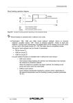
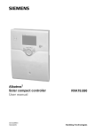
User Manual
for the operator
AQUATOP T/ AEROTOP T/ AEROTOP G/ HIDRON HT
Heat Pump Controller LOGON B WP61 B
05.2011
Art. No. 12 096 697
Table of Contents
Basic Information
Brief Description/Features/Functions .................................................................3
Control Elements................................................................................................ 4
Programming Display Description .....................................................................5
Brief Overview - Main Functions ........................................................................6
End User - Parameterization ............................................................................7
Info Display, Cooling Operation, Reset .............................................................. 9
Error Message / Maintenance .......................................................................... 10
Setting Details
Menu: Time / Date / Control Unit ..................................................................... 11
Menu: Timed Program / Vacation .................................................................... 12
Menu: Heating Circuits...................................................................................... 13
Menu: Cooling Circuits 1 ................................................................................... 15
Menu: Potable Water ....................................................................................... 16
Menu: Pool ...................................................................................................... 17
Menu: Energie Meter ...................................................................................... 17
Technical Data
Technical Data ................................................................................................. 18
Notes .............................................................................................................. 19
2
Basic Information
Brief Description/Features/Functions
Brief Description
The heat pump controller LOGON B
WP61 is a climate-based digital heating
control unit for a mixed heating circuit,
sliding heating circuit, as well as for
potable water preparation. The heat
pump is controlled at the same time as
well. Various additional functions can
be activated.
The control unit calculates based on
the outside temperature sensor the
necessary set-point temperatures for
the heat pump and heating circuits and
controls the potable water preparation.
Optimization functions that can be
additionally activated allow for optional
energy savings.
Features
The heat pump controller has the
following functions:
Operating mode heating, potable
water
Set-point setting for heater,
potable water
Info key
Cooling function
Functions:
Climate-based heat pump controller for
max. one sliding and one mixed circuit.
Potable water control with release and
set-point setting.
Addable time controlled circulation
pump
Potable water solar control with
collector protection function and
heat exchanger option (recooling)
Relay and sensor test for initial
startup
Illuminated display for status and
function displays in plain text,
6 languages
Automatic daylight savings
switching
Preset standard timed programs
for heating and potable water
preparation
Customized switching program with
max. 84 free switching times based
on the controller and system
configuration
Vacation program for each heating
circuit
Buffer storage management
Generator block
Solar heating support
Room temperature control with
add-on equipment
QAA 75 with 2-wire bus
Setting of radiator or floor heating
circuits with program adjustments
Addable automatic heating curve
adaptation
Heating optimization with rapid
heating, addable
Demand-based heating switch off
Adjustable min. and max. flow
temperatures
Pump overrun
Integrated operating hours counter
Energie meter
Thermal disinfection of potable
water, addable (Legionella mode)
2-wire bus interface for additional
controller equipment
Compatible with LPB bus
3
Control Elements
1
9
4
2
5
Operating Mode Key Potable
Water (1)
To switch potable water preparation
on and off. (Bar in display below
water faucet.)
Operating Mode Key Heating
Circuit(s) (2)
Sets 4 different heating operating modes:
Auto time: Automatic operating mode
acc. to timer program
Sun 24-hr: Heating to comfort set-point
Moon 24-hr: Heating to reduced
comfort set-point protect. mode: Heater
is off, frost protection function activated
Info Key (3)
Displays the following information
without affecting control: Temperatures,
operating mode heating/potable water,
error messages
Room Temperature Control
Knob (5)
To change the room comfort
temperature
Use this rotary knob to select and
change settings during the programming step.
4
6
7
3
8
Confirmation Key OK (6)
BACK Key ESC (4)
These two keys are needed together
with the large rotary knob -/+ for
programming and configuring the
controller. Settings not adjustable with
the control elements are changed
through programming.
Press the ESC key to jump one step
back. Set or adjusted values are not
applied with this action.
To open the next control level or to
save changed values, press the OK
key.
Cooling Key (7)
Use the cooling key to select the
"Cooling" operating mode. Cooling is
based on the timer program and the
cooling temperature set-point.
Heat Pump Reset Key
Heat Pump Defrost Function (8)
Briefly press this key to rest the heat
pump error messages. Press this key
longer than 3 seconds to trigger
manually the defrost function for air/
water heat pumps.
Cooling Operation Display (9)
The bar underneath this icon indicates
whether cooling mode is released.
Programming Display
Description
Select potable water mode
Select heating mode
Exit menu
Select
(turn to right / left)
Confirm
Info key
HP reset
Cooling key
Heating to comfort set-point
Heating to reduced comfort set-point
Heating to frost protection set-point
Process running – please wait
Error messages
Info level activated
Programming active
Heater temporarily switched off
ECO function active
Vacation function active
Refers to heating circuit
Maintenance/special function
Number of command line
(parameter number)
Parameterization
Basic Display
(Key Level)
Press OK key (1x)
End user
-
Select desired setting
Confirm with OK key
Use ESC key to return to
basic display
5
Brief Overview - Electronic Controller
Main Functions
Key
Action
Steps
Set
desired room
temperature
HC2 together with HC1
Use left/right rotary knob
Turn rotary knob again
Save with OK key
or wait 5 seconds
or press ESC key
Display/Function
or
Set
room temperature for
HC1 or HC2
Switch potable water
mode
ON or Off
HC2 independent from HC1
Use left/right rotary knob
OK key
Use left/right rotary knob
Save with OK key
or wait 5 seconds
or press ESC key
Automatic mode ON, with:
- Heating operation acc. to timer program
- Temperature set-point acc. to heating program
- Protective functions active
- Automatic daylight savings time switching active
- ECO functions active
(Segment bar under corresponding icon visible)
Cont. heat COMFORT ON, with:
- Heating operation without timer program to comfort set-point
- Protective functions active
Cont. heat REDUCED ON, with:
- Heating operation without timer program to reduced set-point
- Protective functions active
- Automatic daylight savings time switching active
- ECO functions active
Protective mode ON, with:
- Heating switched off
- Temperature acc. to frost protection
- Protective functions active
- Automatic daylight savings time switching active
- ECO functions active
Press key again
Display of var.
information
Press Esc key
Defrosting the
Air heat exchanger
INFO segment is displayed
- Boiler status
- Room temperature
- Solar status
- Min. room temperature
- Drinking water status
- Max. room temperature
- Heating circuit 1 status
- Outside temp.
- Heating circuit 2 status
- Min. outside temperature
- Heating circuit P status
- Max. outside temperature
- Time / date
- Drinking water temperature 1/2
- Error message
- Maintenance message
- Flow (supply) temperature
- Special operating mode
- Customer service phone
(Info line display depends on controller type)
Return to basic display; INFO segment is hidden
Press key briefly
In cooling mode, the room temperature is controlled in dependence
the timer program and the temperature set-point.
In the display, the bar is depicted underneath the ice crystal icon.
Press key briefly
Pending error messages are reset. The switch-on delay is bridged.
In normal operation mode, do not press key. Display depicts ―Reset
heat pump Yes‖
Press key at least 3 seconds
In case of an air/water heat pump, manual
air heat exchanger defrosting is possible. After successful
defrosting, the heat pump is automatically released.
= Confirmation
6
Comfort set-point applied
Comfort set-point not applied
- basic display is depicted after 3 seconds
Factory setting
Press key 1x
Press key again
Press key again
…..
Reset / restart of the
heat pump after
error messages
Select heating circuit
Heating circuit is applied
Flashing temperature display in steps of 0.5°C from 10.0 to 30°C
Drinking water mode ON/OFF
(Segment bar under potable water icon visible/hidden)
- ON: Drinking water prep. acc. to switching program
- OFF: No potable water prep.
- Protective functions active
Press key again
Activate
cooling mode
Comfort set-point applied
Comfort set-point not applied
- Basic display is depicted after 3 seconds
Press key
Press key 1x
Change operating
mode or cycle
Comfort set-point with flashing temperature display
Flashing temperature display in steps of 0.5°C from 10.0 to 30°C
= Cancel or return to basic display
End User - Parameterization
Basic display "Heat Pump Status"
Press 1 x OK key
Use +/- rotary knob to select "Potable Water Menu"
Press 1 x OK key
Use +/- rotary knob to select "Parameter No. 1612 Reduced Set-Point," for example from potable water menu
Press 1 x OK key
Use +/- rotary knob to change current value
Press 1 x OK -> value is saved
Press 2 x ESC key to return to basic display "Heat Pump Status"
Menu Selection
Time and date
Operator section
Timer program
heating circuit 1
Timer program
heating circuit 2
(only if active)
Timer program 3
HCP
Timer program 4
DHW
Command Selection Option
Line
Unit
hh:mm
dd:MM
yyyy
-
Min.
Max
1
2
3
20
Hours/minutes
Day/month
Year
Language selection
29
Units
_
500
Preset value
-
501
502
503
504
505
506
515
516
520
Mon-Sun: Phase 1 ON
Mon-Sun: Phase 1 OFF
Mon-Sun: Phase 2 ON
Mon-Sun: Phase 2 OFF
Mon-Sun: Phase 3 ON
Mon-Sun: Phase 3 OFF
Copy day
Default values
Preset value
hh:mm
hh:mm
hh:mm
hh:mm
hh:mm
hh:mm
-
521
522
523
524
525
526
535
536
540
Mon-Sun: Phase 1 ON
Mon-Sun: Phase 1 OFF
Mon-Sun: Phase 2 ON
Mon-Sun: Phase 2 OFF
Mon-Sun: Phase 3 ON
Mon-Sun: Phase 3 OFF
Copy day
Default values
Preset value
hh:mm
hh:mm
hh:mm
hh:mm
hh:mm
hh:mm
-
541
542
543
544
545
546
555
556
560
Mon-Sun: Phase 1 ON
Mon-Sun: Phase 1 OFF
Mon-Sun: Phase 2 ON
Mon-Sun: Phase 2 OFF
Mon-Sun: Phase 3 ON
Mon-Sun: Phase 3 OFF
Copy day
Default values
Preset value
hh:mm
hh:mm
hh:mm
hh:mm
hh:mm
hh:mm
-
561
Mon-Sun: Phase 1 ON
hh:mm
562
Mon-Sun: Phase 1 OFF
hh:mm
00:00
563
564
565
566
575
Mon-Sun: Phase 2 ON
Mon-Sun: Phase 2 OFF
Mon-Sun: Phase 3 ON
Mon-Sun: Phase 3 OFF
Copy day
hh:mm
hh:mm
hh:mm
hh:mm
-
00:00
24:00
00:00
24:00
00:00
24:00
00:00
24:00
Mon, Tue, Wed, Thu, Fri, Sat, Sun
576
Default values
-
Factory
Settings
00:00
23.59
01.01
31.12.
2004
2099
English, German, Francais, Italiano,
Nederlands, Polski
°C/bar, °F/PSI
`--.-`--.-`--.-German
Mon-Sun, Mon-Fri,
Mon, Tue, Wed, Thu, Fri,
Sat-Sun
Sat, Sun
00:00
24:00
00:00
24:00
00:00
24:00
00:00
24:00
00:00
24:00
00:00
24:00
Mon, Tue, Wed, Thu, Fri, Sat, Sun
Yes
No
Mon-Sun, Mon-Fri,
Mon, Tue, Wed, Thu, Fri,
Sat-Sun
Sat, Sun
00:00
24:00
00:00
24:00
00:00
24:00
00:00
24:00
00:00
24:00
00:00
24:00
Mon, Tue, Wed, Thu, Fri, Sat, Sun
Yes
No
Mon-Sun, Mon-Fri,
Mon, Tue, Wed, Thu, Fri,
Sat-Sun
Sat, Sun
00:00
24:00
00:00
24:00
00:00
24:00
00:00
24:00
00:00
24:00
00:00
24:00
Mon, Tue, Wed, Thu, Fri, Sat, Sun
Yes
No
Mon-Sun, Mon-Fri,
Mon, Tue, Wed, Thu, Fri,
Sat-Sun
Sat, Sun
00:00
24:00
Mon-Sun
Yes
24:00
No
°C/bar
06:00
22:00
`--.-`--.-`--.-`--.-No
Mon-Sun
06:00
22:00
`--.-`--.-`--.-`--.-No
Mon-Sun
06:00
22:00
`--.-`--.-`--.-`--.-No
Mon-Sun
00:00
06:00
`--.-`--.-`--.-`--.-No
7
End User - Parameterization
Menu Selection
Holidays heating
circuit 1
Holidays heating
circuit 2
(only if active)
Holidays heating P
(only if active)
Heating circuit 1
Cooling circuit
(only if active)
Heating circuit 2
(only if active)
Heating circuit P
(only if active)
Domestic hot water
Pool (only if active)
Energie meter
8
Command
Line
641
642
643
648
651
652
653
658
661
662
663
668
710
Selection Option
Unit
Min.
Max
Preset value
Start day/month
End day/month
Operating level
Preset value
Start day/month
End day/month
Operating level
Preset value
Start day/month
End day/month
Operating level
Comfort set-point
dd.MM
dd.MM
dd.MM
dd.MM
dd.MM
dd.MM
°C
Period 1
01.01
01.01
Frost protection
Period 1
01.01
01.01
Frost protection
Period 1
01.01
01.01
Frost protection
Period 8
31.12
31.12
Reduced
Period 8
31.12
31.12
Reduced
Period 8
31.12
31.12
Reduced
35
712
Reduced set-point
°C
714
Frost protection set-point
°C
4
720
730
901
902
907
1010
Slope of characteristic curve
Summer/winter heating limit
Operating mode
Comfort set-point
Release
Comfort set-point
°C
°C
°C
0.10
---/8
Off
15
1012
Reduced set-point
°C
1014
1020
1030
1300
1310
Frost protection set-point
Slope of characteristic curve
Summer/winter heating limit
Operating mode
Comfort set-point
°C
°C
°C
1312
Reduced set-point
°C
line 1312
Value from command
line 1314
1314
Frost protection set-point
°C
4
1320
1330
1610
Slope of characteristic curve
Summer/winter heating limit
Set-point
°C
°C
0.10
---/8
1612
Reduced set-point
°C
2055
2056
3110
3121
3128
3135
3142
3149
3156
3163
3170
3177
3184
3122
3129
3136
3143
3150
3157
3164
3171
3178
3185
Solar heating set-point
Generator heating set-point
Heat delivered
Heat delivered heating 1
Heat delivered heating 2
Heat delivered heating 3
Heat delivered heating 4
Heat delivered heating 5
Heat delivered heating 6
Heat delivered heating 7
Heat delivered heating 8
Heat delivered heating 9
Heat delivered heating 10
Heat delivered DHW 1
Heat delivered DHW 2
Heat delivered DHW 3
Heat delivered DHW 4
Heat delivered DHW 5
Heat delivered DHW 6
Heat delivered DHW 7
Heat delivered DHW 8
Heat delivered DHW 9
Heat delivered DHW 10
Value from command
line 712
Value from command
line 714
Value from command
line 710
Value from command
line 712
16.0
4.00
30
Automatic
40
0.8
20
Automatic
24
24 hrs
20.0
24-hrs/day, timer program HC, timer program 5
Value from command
line 1012
Value from command
line 1014
Factory
Settings
Period 1
`--.-`--.-Frost protection
Period 1
`--.-`--.-Frost protection
Period 1
`--.-`--.-Frost protection
20.0
35
Value from command
line 1010
Value from command line 1012
4
0.10
4.00
---/8
30
Protective mode, automatic, reduced, comfort
Value from command
35
10.0
16.0
10.0
0.8
20
Automatic
20.0
Value from command
line 71310
Value from command
line 1312
16.0
4.00
30
65
1.50
20
50
8
Value from command
line 1610
45
°C
°C
kWh
kWh
8
8
0
0
80
80
9999999
9999999
26
22
——-
kWh
0
9999999
—-
Value from command
line 1612
10.0
Info Display
Cooling Mode
Reset
Display Information
Use the info key to query and display
various information.
AUTO
Room
temperature
Raumtemperatur
0
Possible Info Values
Depending on unit type, configuration,
and operating state, individual info
lines are hidden.
4
8
12
16
20
Fault message
Maintenance message
Special operating mode
Room temperature
Min. room temperature
Max. room temperature
Outside temperature
Min. outside temperature
Max. outside temperature
24
Potable water temperature 1/2
Heat pump status
Solar status
Potable water status
Status heating circuit 1/2
Status heating circuit P
Solar energy yield
Time / date
Customer service phone
Cooling Mode
Use the cooling key to select the
cooling mode. Cooling is carried out
based on the timer program and acc.
to the temperature set-points.
HP Reset Key/ (HP Defrost Function)
Briefly press the reset key to reset
the error and fault messages. The
switch-on delay is bridged. The reset is
applied two seconds after releasing
the reset key. Do not use this function
during normal operation!
9
Error Message / Maintenance
Error Message / Maintenance
In rare cases, the basic display depicts
one of the following icons:
Error messages
If this symbol is depicted, a system
malfunction has occurred. Press the
info key for additional information.
Maintenance or special op
If this symbol is depicted, a service
message has been issued or a
special operating mode applies.
Press the info key for additional
AUTO
AUTO
Fehler
Error
30:Vorlauffühler
1 1
30: Flow sensor
Text3
0
4
8
12
16
Maintenance
Wartung
3:Wartungsintervall
3: Maintenance interval
Text3
Text4
Text4
20
24
0
4
8
12
16
20
24
Display Lists
Error Code
Error
Code
10
30
31
32
33
35
36
44
45
50
52
60
65
68
70
71
72
73
74
76
81
82
83
84
98
99
100
102
105
121
10
Error Description
Outside sensor
Flow sensor 1
Flow sensor cooling 1
Flow sensor 2
Flow sensor HP
Source inlet sensor
Hot gas sensor 1
HP return flow sensor
Source outlet sensor
Potable water sensor 1
Potable water sensor 2
Room sensor 1
Room sensor 2
Room sensor P
Buffer storage sensor 1
Buffer storage sensor 2
Buffer storage sensor 3
Collector sensor 1
Collector sensor 2
Special sensor 1
LPB short-circuit/comm
LPB address collision
BSB short-circuit
BSB address collision
Expansion module 1
Expansion module 2
Two time source masters
Clock power reserve
missing
Maintenance message
Flow temp. HC1 too low
Error
Code
122
126
127
134
138
146
201
204
222
225
226
228
229
230
247
324
325
327
329
Error Description
Flow temp. HC2 too low
Potable water charge
monitoring
Legionella temp.
Accum. fault HP
Control sensor HP missing
Sensor/actuator config
Frost alarm
Fan overload
High pressure with HP
operating
Low pressure
Compressor 1 K1 overload
Flow mon. heat source
Heat source pressure
monitor
Source pump overload
Defrosting fault
BX same sensors
BX/E. mod. same sensors
330
331
332
333
334
335
E. module same function
E. mod./M. group same
function
BX1 no function
BX2 no function
BX3 no function
BX4 no function
BX5 no function
BX21 no function
336
339
340
BX22 no function
Collector pump Q5 missing
Collect. pump Q16 missing
341
Collect. sensor B6 missing
Error
Code
343
Error Description
Solar integration missing
344
Solar buffer K8 missing
353
355
356
358
359
360
Casc. sensor B10 missing
Asymmetrical three-phase
current
Flow mon. cons.
Soft-starter
Cooling valve Y21 missing
Process valve Y22 missing
361
Source inlet B91 missing
362
Source outlet B92 missing
363
364
365
Evap. sensor B84 missing
Cooling HP incorrect
DHW rotary pump Q34
missing
Room humidity sensor Hx
367
Maintenance code
Mainte- Maintenance
nance Description
Code
10
Battery replacement
outside sensor
Settings Details
Menu: Time / Date / Control Unit
Time and Date
The controller is equipped with an
internal clock keeping track of the time,
day of the week, and the date. To
ensure the functionality of the clock, the
time and date must be set correctly.
Line No.
Control and Display
Line No.
Language
The following display languages are
available: German, English, Italian,
French, Dutch or Polski.
Command Line
1
Hours/minutes
2
Day/month
3
Year
Factory Setting
Command Line
Factory Setting
20
Language
German
22
Info, temporary, permanent
Temporary
26
Operating lock
OFF
27
Programming lock
OFF
Command Line
Factory Setting
Units
°C / bar
Units
The display can be switched between
the SI units (° C, bar) and U.S. units
(° F, PSI).
Line No.
29
°C / bar
°F/PSI
11
Menu: Timer Programs
Menu: Vacation
Various switching programs are
available for the heating circuits and the
heating/preparation of potable water.
With operating mode "Automatic"
switched on, use the set switching
times to control the change of the
temperature level (and the associated
set-points).
Entering Switching Times
Switching times can be combined,
i.e. for several days together or for
individual days or times. By preselecting day groups such as Mon ... Fri.
and Sat...Sun that are to have the
same switching times, setting up the
switching times will be significantly
quicker.
Switching Points
Line No.
HC1 HC2 3/HCP 4/DHW
500
520
540
560
Command
Line
Preselected
HC1, HC2,
3/HCP
4/DHW
Mon-Sun
Mon-Sun
Mon-Sun
Mon-Fri
Sat-Sun
Mon…Sun
501
521
541
561
Phase 1 ON
06 : 00
00:00
502
522
542
562
Phase 1 OFF
22 : 00
06:00
503
523
543
563
Phase 2 ON
--:--
--:--
504
524
544
564
Phase 2 OFF
--:--
--:--
505
525
545
565
Phase 3 OFF
--:--
--:--
506
526
546
566
Phase 3 OFF
--:--
--:--
Copy day
Line No.
Command Line
515, 535, 555, 575
Default Program
Line No.
Copy day
Command Line
516, 536, 556, 576
Default values
All timed switching programs can be
reset to the default factory settings.
Each timed switching program has its
own command line for resetting.
Vacation
Line No.
Note
All customized settings are lost with a
reset!
Command Line
Factory Setting
HC1
HC2
HCP
642
652
662
Start
--:--
643
653
663
End
--:--
648
658
668
Operating level
Frost protection
Frost protection
Reduced
Use the vacation program to switch the
heating circuits to a selectable operating
level based on a specific date (by
calendar).
The vacation program can be used
only while the system is in automatic operating mode.
12
Factory Setting
Menu: Heater Circuits
Various switching programs are
available for the heating circuits, which
can be set individually for each heating
circuit. Use the configuration menu to
activate HC2 (mixed circuit 2) and/or
HCP (sliding pump circuit).
Operating Mode
The operating mode of heating circuits
1 and 2 can be controlled directly with
the operating mode key while the heating circuit P operating mode is set with
the programming function (command
line 1300).
The setting is used to toggle between
the individual operating modes. The
functionality corresponds with the
operating mode selection with the
operating mode key.
Room Set-Points
Room Temperature
The room temperature can be adjusted
based on different set-points.
Depending on the selected operating
mode, these set-points are applied and
thereby result in different temperature
levels in the temperature-controlled
rooms.
The range of the adjustable set-points
is based on their mutual interdependency as depicted in the chart.
Frost Protection
While in protection mode, room
temperatures are automatically prevented from dropping too low.
Temperatures are in this case based
on the room temperature frost
protection set-point.
Characteristic Heating Curve
The characteristic heating curve is
used to define the flow temperature
set-point, which in turn is used to
control temperatures to a corresponding flow temperature based on the
current climate conditions. The
characteristic heating curve can be
adjusted here so that the heat output
and with that the room temperature is
in accordance with personal needs.
Line No.
Command Line
Factory Setting
1300
Operating mode
Automatic
Automatic
Comfort
Reduced
Protective mode
HC1
710
712
714
Line No.
HC2
HCP
1010
1310
1012
1014
TRKmax
TRK
TRR
TRF
1312
1314
Command Line
Factory Setting
Comfort set-point
20°C
Reduced set-point
Frost protection set-point
16°C
10°C
comfort set-point max.
Comfort set-point
Reduced set-point
Frost protection set-point
Line No.
HC1
HC2
HCP
720
1020
1320
Command Line
Factory Setting
Slope of characteristic curve
0,80
13
Menu: Heating Circuits
Slope of Characteristic Curve
The steepness of the slope determines
the flow temperature (higher the colder
the outside temperature). This means
that if the room temperature deviates
with cold outside temperatures and not
with warm outside temperatures, the
steepness of the slope must be
adjusted.
Increase setting:
Increases the flow temperature
primarily with cold outside temperatures.
Decrease setting:
Decreases the flow temperature
primarily with cold outside temperatures.
14
Menu: Cooling Circuit 1
To utilize the cooling circuit, the
corresponding hydraulics options with
heating/cooling must be set.
The cooling operating mode is automatically triggered when the room
temperature rises above the comfort
set-point defined for cooling (command
line 902).
Operating Mode
The operating mode is set with the
operating mode key on the room or
control unit, the controller, or with this
command line.
The cooling function must be switched
on (command line 901 = auto) and
released based on the timer switching
program or activated for 24-hrs
(command line 907).
heating circuit is pending (only with
active cooling).
With passive cooling, a service water
charging and heating with a different
heating circuit are possible during
cooling mode.
The cooling mode is canceled if heating
circuit 1 requires heat or if a heating
request by the service water or another
Line No.
901
Command Line
Operating mode
Factory Setting
Automatic
Off: Automatic*
OFF
The cooling function is switched off.
Automatic
The cooling function is automatically switched on based on the selected timer
switching program (command line 907), the vacation program, the presence
key, and when needed.
Set Point
Comfort Set-Point
Line No.
902
Command Line
Comfort set-point
Factory Setting
24°
While in cooling mode, the room temperature is adjusted to the comfort set-point
specified here. The cooling comfort set-point can also be adjusted with the rotary
knob on the room control unit.
During summer, comfort set-point is adjusted based on the outside temperature
(sliding).
Release
Line No.
907
Command Line
Release
Factory Setting
24°
24-hr/day: Timer program heating
circuit: Timer program 5
The parameter "Release" determines which timer switching program is used for
releasing the cooling mode.
24-hr/Day
Cooling is released for 24-hr/day.
Heating Circuit Timer Program
The cooling release is based on the timer switching program of the heating circuit.
Timer Program 5
The cooling release is based on timer switching program 5.
15
Menu: Domestic hot water
Set-Points
Domestic hot water can be adjusted
based on different set-points. Depending on the selected operating mode,
these set-points are applied and
thereby result in different temperature
levels in the DHW storage.
Line No.
Command Line
Factory Setting
1610
Set-point
50°C
1612
Reduced set-point
45°C
TWWR
TWWN
TWWmax
16
DHW reduced set-point
DHW nominal set-point
DHW max. nominal set-point
Menu: Pool
Menu: Heat flow metering
If the pool control is enabled, the
set-points for heating with solar energy
or heat pump can be set.
Line No.
Solar Heating Set-Point
The pool water temperature is charged
up to this specified set-point when
using solar energy.
Command Line
Factory Setting
2055
Solar heating set-point
26 °C
2056
Generator heatingsSet-point
22 °C
Generator Heating Set-Point
The pool water temperature is charged
up to this specified set-point when
using the heat pump.
Heat flow metering
Activated heat flow metering shows
amount of energy during heating demand and DHW charge.
Heat delivered (3110)
Sum of heat pump output for heating
demand and DHW charge since starting up. In case of inactive heat flow
metering, display shows ―----―.
Heat delivered heating (3121 – 3184)
End of period is always 30.06. per year.
The sum of the heat pump output for
heating demand up to this date is
saved in parameter 3121. Parameter
3128 saves the value of the previous
year. Altogether the values of the last
10 periods are visible.
Heat delivered DHW (3122 – 3185)
End of period is always 30.06. per year.
The sum of the heat pump output for
DHW charge up to this date is saved in
parameter 3122. Parameter 3129
saves the value of the previous year.
Altogether the values of the last 10
periods are visible.
Line No.
Command Line
Factory Setting
3110
Heat delivered
Value in kWh
Heat flow metering HC end of period
Heat delivered heating 1
Heat delivered heating 2
Heat delivered heating 3
Heat delivered heating 4
Heat delivered heating 5
Heat delivered heating 6
Heat delivered heating 7
Heat delivered heating 8
Heat delivered heating 9
Heat delivered heating 10
Value in kWh
3121
3128
3135
3142
3149
3156
3163
3170
3177
3184
Heat flow metering DHW end of period
Heat delivered DHW 1
Heat delivered DHW 2
Heat delivered DHW 3
Heat delivered DHW 4
Heat delivered DHW 5
Heat delivered DHW 6
Heat delivered DHW 7
Heat delivered DHW 8
Heat delivered DHW 9
Heat delivered DHW 10
Value in kWh
3122
3129
3136
3143
3150
3157
3164
3171
3178
3185
17
Technical Data
Supply
Terminal wiring
Function data
Inputs
Rated voltage
Rated frequency
Maximum power consumption
(Supply and outputs)
Software category
Function acc. to EN 60730
Digital inputs H1/ H3
Analog inputs H1/ H3
Power input EX1-7, E9-11
Outputs
Interfaces
IP and protection class
Standards, safety, EMC, etc.
Ambient environment conditions
18
Sensor input B9 outside sensor
Sensor inputs B1, B2, B3, B12, BX1-5,
B4, B41, B21, B71, B81, B91, and B92
Permiss. sensor wires (Cu) with wire
cross section
Maximum length
Relay outputs
Rated current range
Max. starting current
Max. total current (all relays)
Rated voltage range
Output Q4 mod.
Rated current range
ON/OFF mode
Speed control
Max. starting current
Analog output UX
Output voltage
Current loading
Ripple
Zero point accuracy
Remaining range error
BSB
Max. line length
LOGON B HP peripheral device
Max. line length
Min. wire cross section
IP acc. to EN 60529
Protection class acc. to EN 60730
Degree of pollution acc. to EN 60730
CE Conformity acc. to
EMC Directive
- Interference resistance
- Emissions
Low Voltage Directive
Electrical Safety
Storage acc. to IEC721-3-1 Class 1K3
Transport acc. to IEC721-3-2 Class 2K3
Operation acc. to IEC721-3-3 Class 3K5
AC 230 V (± 10%)
50/60 Hz
LOGON B WP: 11 VA
Wire or stranded conductor
(paired or with wire end ferrule):
1 wire: 0.5 mm2 ... 2.5 mm2
2 wires 0.5. mm2..1.5 mm2
A
1 b (automatic function)
Extra low voltage protection for potential-free
contacts compatible with extra low voltage:
Voltage with open contact: DC 12 V
Current with closed contact: DC 3 mA
Protective extra low voltage
Working range: DC (0 ... 10) V
Interior resistance: > 100 kW
AC 230 V (± 10 %)
Interior resistance: > 100 kW
NTC1k (QAC34)
NTC10k (QAZ36, QAD36)
0.25
20
0.5
40
0.75
60
1.0
80
1.5 (mm2)
120 (m)
AC 0.02...2 (2) A
15 A during 1 s
AC 10 A
AC (24...230) V (for potential-free outputs)
AC 0.05
2 (2) A
AC 0.05
1.4 (1.4) A
4 A during 1 s
Output is short-circuit proof
Uout = 0 ... 10.0 V
±2 mA RMS; ±2.7 mA peak
50 mVpp
< ± 80 mV
130 mV
2 Wire connection not exchangeable
200 m
400 m max. cable capacity: 60 nF)
0.5 mm2
IP 00
Extra low voltage components if properly
installed meet requirements for protection
class II
Normal pollution
89/336/EWG
- EN 61000-6-2
- EN 61000-6-3
73/23/EWG
- EN 60730-1, EN 60730-2-9
Temp. -20…65 °C
Temp. -25…70°C
Temp. 0...50 °C (without condensation)
Notes
19
Service:
ELCO GmbH
D - 64546 Mörfelden-Walldorf
ELCO Austria GmbH
A - 2544 Leobersdorf
ELCOTHERM AG
CH - 7324 Vilters
ELCO-Rendamax B.V.
NL - 1410 AB Naarden
ELCO Belgium n.v./s.a.
B - 1731 Zellik
ELCO
I - 31023 Resana