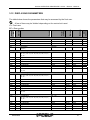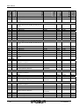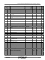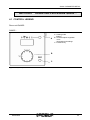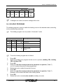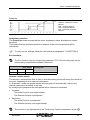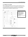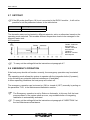
1
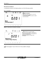
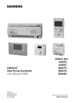
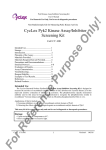
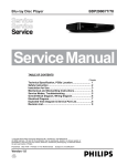
User manual
Comfort Control Panel
E3 systems control device
User manual
EDITION: 06/2008
Code: D-LBR523
This booklet has been edited and printed by Robur S.p.A.; any form of even partial
reproduction of this manual is forbidden.
The original is archived at the premises of Robur S.p.A.
Any use of the manual other than for consultation purposes must be authorized in
advance by Robur S.p.A.
The rights of the rightful owners of the registered trademarks included in this publication
are protected.
With the aim of improving the quality of its products, Robur S.p.A. reserves the right to
modify, without prior warning, the information and content of this manual.
II
Ed. 06/2008
Index
SUMMARY
SECTION 1 PREFACE......................................................................................................2
SECTION 2 OVERVIEW AND TECHNICAL CHARACTERISTICS ..................................4
2.1
2.2
WARNINGS .....................................................................................................................................4
SPECIFICATIONS...........................................................................................................................4
SECTION 3 OPERATING PROCEDURE: AVS37…/QAA75…/QAA78…........................7
3.1
3.2
3.3
3.4
3.5
3.6
3.7
3.8
3.9
3.10
3.11
3.12
CONTROL LEGEND .......................................................................................................................7
DISPLAY SYMBOLS .......................................................................................................................8
SELECTION OF HEATING MODE .................................................................................................9
COOLING OPERATING SELECTION ..........................................................................................11
SELECTING THE ACS HEATING MODE.....................................................................................11
ROOM TEMPERATURE SETPOINT CORRECTION...................................................................12
PRESENCE KEY...........................................................................................................................13
INFORMATION DISPLAY .............................................................................................................14
MANUAL/RESET CONTROL ........................................................................................................17
RESET HEAT PUMP.....................................................................................................................17
PROGRAMMING...........................................................................................................................18
DISPLAYING PARAMETERS .......................................................................................................21
SECTION 4 OPERATING PROCEDURE QAA55… .......................................................25
4.1
4.2
4.3
4.4
4.5
4.6
4.7
CONTROL LEGEND .....................................................................................................................25
DISPLAY SYMBOLS .....................................................................................................................26
SELECTION OF HEATING MODE ...............................................................................................27
COOLING MODE SELECTION (IF AVAILABLE)..........................................................................28
ROOM TEMPERATURE SETPOINT CORRECTION...................................................................28
PRESENCE KEY...........................................................................................................................28
CHANGE SETTINGS ....................................................................................................................29
SECTION 5 PARAMETER DETAIL ................................................................................30
5.1
5.2
5.3
5.4
5.5
5.6
5.7
5.8
LANGUAGE...................................................................................................................................30
TIME AND DATE ...........................................................................................................................31
HOURLY PROGRAM ....................................................................................................................31
HOLIDAY PROGRAM ...................................................................................................................33
HEATING CIRCUIT .......................................................................................................................34
DOMESTIC HOT WATER .............................................................................................................37
SETPOINT.....................................................................................................................................38
EMERGENCY OPERATION .........................................................................................................38
SECTION 6 HANDLING OF ERRORS............................................................................39
6.1
6.2
ERROR HISTORY.........................................................................................................................39
ERROR RESET.............................................................................................................................39
Ed.06/2008
1
User manual
SECTION 1
PREFACE
This “User manual” provides information on the use and configuration of the Comfort
Control device, a control device for hydronic heating systems with heat pump and
modulated condensation absorption.
The consultation of this manual implies knowledge of Robur products and of the
information contained in the installation, use and maintenance manuals.
This manual is specifically intended for:
• the final user, for the use and configuration of the equipment depending on their
own needs.
•
to installation technicians(hydraulic and electrical) to ensure correct installation and
configuration of the equipment.
Summary
The manual has 6 sections:
SECTION 1 addressed tousers and hydraulic installers, provides general indications on
the equipment used.
SECTION 2 provides a few general indications on the Siemens appliances and their
possible applications
SECTION 3 and SECTION 4 provide details on the functions of the devices.
SECTION 5 illustrates how the final user should use the appliance and how the
parameters of the appliance may be modified.
SECTION 6 provides suggestions concerning possible errors that may occur.
Glossary
ACS
CR
CR1 or C1
CR2 or C2
CRP or CP
2
sanitary (domestic) hot water
Heating circuit
Heating Circuit 1 (with mixer valve)
Heating circuit 2 (with mixer valve)
Heating circuit pump (without mixer valve)
Ed. 06/2008
Section OVERVIEW AND TECHNICAL CHARACTERISTICS
References
For requirements other than those shown in this manual, please consult the manuals:
Comfort Control “Installation and application manual” (D-LBR514)
(addressed to installation technicians and service personnel);
“Comfort Control Interface [CCI]” (D-LBR526)
(addressed to installation technicians and service personnel)
The icons present in the margins of the manual have the following meaning:
Danger warning
)
WARNING
Note
Start operating procedure
Reference to another part of the manual or other manual
Table 1
Descriptive icons
Ed.06/2008
3
User manual
SECTION 2
OVERVIEW AND TECHNICAL
CHARACTERISTICS
2.1 WARNINGS
This manual constitutes an integral and essential part of the product and must be
delivered to the user together with the appliance.
Safety
The appliance must only be used for the purposes for which it has been designed.
Any other use is considered inappropriate and therefore dangerous. The
manufacturer does not accept any contractual or extra-contractual liability for any
damage caused by improper use of the appliance.
Failure to comply with the above indications may compromise the product's safety
and may invalidate the warranty provided by Robur.
Do not start the appliance if, at the time of use, there seem to be dangerous
conditions such as: problems with the power grid; parts of the appliance underwater
or otherwise damaged; control and safety components bypassed or faulty.
In these instances call in professionally qualified personnel for assistance
Keep packaging items (plastic bags, polystyrene foam, insulation materials, spacers) out
of the reach of children, as they represent a potential source of danger.
2.2 SPECIFICATIONS
In Figure 1 are illustrated the devices included in the Comfort Control Panel (CCP), or that
interface with them, in order to manage the Robur hydronic heating systems.
4
Ed. 06/2008
Section OVERVIEW AND TECHNICAL CHARACTERISTICS
Figure 1
Initial description of the Comfort Control system
Ed.06/2008
5
User manual
Product code (ASN) Description
RVS61.843 Main controller
AVS75.390 Additional module
AVS37.294 Control unit
QAA75.610 Room unit, cable operated
QAA75.611 Back lit room unit, cable operated
QAA78.610 Radio operated room unit
QAA55.110 Type of room unit
AVS38.291 Cover (96 x 144 mm)
AVS71.390 Radio module
AVS14.390 Radio relay
AVS13.399 External temperature sensor with radiotransmitter module
AVS82.490 Flat band cable of the additional module
AVS82.491 Flat band cable of the control unit
Table 2
6
Product list
Ed. 06/2008
Section OPERATING PROCEDURE: AVS37…/QAA75…/QAA78…
SECTION 3 OPERATING PROCEDURE:
AVS37…/QAA75…/QAA78…
This section explains how the appliances should be used and their operating
characteristics.
3.1
CONTROL LEGEND
ROOM UNIT
QAA75../ QAA78..
USER INTERFACE
Avs37..
AVS37.../ QAA75.../ QAA78...
Figure 2
A - ACS heating selection
B - Operating mode
selection
C - Information
D - Confirm setting
E - WP reset key
F - Manual control
G - Room Comfort Setpoint
correction
- Navigation and configuration
parameters
H - Setting cancellation
I - Service connector (BSB)
L - Presence key
Description of the AVS37… user interface controls and for room units QAA75.../QAA78...
Ed.06/2008
7
User manual
3.2
DISPLAY SYMBOLS
Heating at Comfort Setpoint
Heating at reduced Setpoint
Heating at freeze protection Setpoint
Cooling
Processing - please wait
Replace batteries
Active vacation function
Refers to the heating circuit
Special mode / Maintenance
Error message
ACS mode
Automatic operation
Protection mode
INFO
Info level active
PROG
Programming on
ECO
Heating system temporarily Off / ECO functions on
Display
8
Ed. 06/2008
Section OPERATING PROCEDURE: AVS37…/QAA75…/QAA78…
Figure 3
3.3
The Display shows all available segments
SELECTION OF HEATING MODE
Heating mode
Press the button to select the different heating modes.
The selected mode is indicated by a bar beneath the
relative symbol.
Automatic operation
Automatic operation checks the room temperature based on a set time sequence.
Features of the automatic operation:
¾ Heating mode based on a time sequence.
¾ Temperature setpoint dependent on the “Setpoint Comfort”
or “reduced
Setpoint”
¾ Active protection systems (Antifreeze).
¾ Automatic switching between summer/winter operations (ECO functions and
24 hour daily heating off restriction.
Ed.06/2008
9
User manual
Continuous operation
or
Continuous operation maintains the room temperature at the selected level.
•
Heating at Comfort setpoint
•
Heating at Reduced setpoint
Features of continuous operation:
¾ Heating with programmed timing off.
¾ Active protection systems (Antifreeze).
¾ Automatic switching between summer/winter operations (ECO functions and 24 hour
daily heating off limitation for continuous operation with Comfort setpoint.
Protection mode
Using the Protection mode the heating is off, but the antifreeze protection is in
operation(antifreeze protection temperature).
Features of the Protection mode:
¾
¾
¾
¾
Heating OFF.
Temperature according to antifreeze protection.
Active protection systems (Antifreeze).
Automatic switching between summer/winter operations (ECO functions and 24 hour
daily heating off restriction.
The heating mode is also selectable through the following parameters:
900 C1; 1200 C2; 1300 CP.
For more circuits configured in the same room unit, the set operating mode, is the
same for all associated circuits (for example if C1 and CP are both configured on
the room unit 1, by pressing the “Operating mode” button the mode is set for both
the C1 and for the CP) The same is true for the devices QAA75../78.. and for
devices AVS37…
If the operating mode is set on the interface AVS37… with C1 independent of C2
“Parameter44”, to change the operating mode, after pressing the “Operating mode”
button, one must choose the circuit one intends to modify, and then set the
operating mode for the chosen circuit.
10
Ed. 06/2008
Section OPERATING PROCEDURE: AVS37…/QAA75…/QAA78…
3.4
COOLING OPERATING SELECTION
Cooling mode
Using the cooling button one selects the “cooling” function. A bar among
the display symbols indicates the chosen selection.
The “cooling” function adjusts the room temperature based on an hourly
schedule.
Features of the cooling function:
¾
¾
¾
¾
¾
Manual mode
Cooling according to an hourly schedule.
Temperature set according to the “Cooling to Comfort setpoint”.
Protective function on (Antifreeze)
Limitation of cooling dependent on external temperature.
The cooling operation can also be selected with parameters 969.
3.5
SELECTING THE ACS HEATING MODE
ACS heating mode
The button is used to enable and disable the heating of domestic
tap water (ACS). The selected choice is indicated by a bar placed
in conjunction with the relative symbol.
ACS mode
¾ ON - The domestic water is heated according to the selected program.
¾ OFF - Domestic water is not heated; The protection mode is active.
Ed.06/2008
11
User manual
3.6
ROOM TEMPERATURE SETPOINT CORRECTION
Knob
Figure 4
Setpoint correction knob
For the Comfort setpoint
Rotate the knob to increase the setpoint (clockwise) or to decrease it (anti-clockwise).
Confirm by pressing the OK button.
When the heating mode is active one modifies the Comfort heating setpoint, when the
cooling mode is active one modifies the Comfort cooling setpoint.
For more circuits configured through the same room unit, the Comfort setpoint
set is the same for all associated circuits (ex. if C1 and CP are both configured
on the room unit 1, by turning knob one sets the same setpoint for both circuits).
The same is true for the devices QAA75../78.. and for devices AVS37…
If the operating mode is set on the interface AVS37… with C1 independent of C2
“Parameter44”, to change the Comfort setpoint
one has to turn the knob to
select the circuit for which one wants to change the setpoint and then press OK;
at this point one can change the Comfort setpoint
of the chosen circuit.
For the Reduced setpoint
-
press the OK button
Select the section “Heating circuit”
press the OK button
Select the section “Reduced setpoint”
press the OK button
Modify the “Reduced setpoint”
Press the OK button to confirm
Press the ESC button to return to the main screen
After having carried out the change wait at least 2 hours to allow the requested
room temperature to be reached.
The Reduced setpoint can be selected only with the heating function on.
12
Ed. 06/2008
Section OPERATING PROCEDURE: AVS37…/QAA75…/QAA78…
The reduced setpoint can also be using the following parameters:
712 CR1; 1012 CR2; 1312 CRP.
For the cooling system only the Comfort setpoint is operational.
3.7
PRESENCE KEY
When the premises are not occupied for a certain period of time, by
pressing the presence key, the room temperature is reduced, allowing
a saving in energy consumption.
To return to the Comfort heating mode one just has to press the key
again.
When the premises are occupied once more, press the presence key once more in order
to put the heating (Switching from Reduced setpoint to Comfort setpoint) or the cooling
(Switching from cooling OFF to Comfort setpoint) back on.
In heating mode:
¾ Heating at Comfort setpoint
¾ Heating at Reduced setpoint
In cooling mode:
¾ Cooling to Comfort setpoint
¾ Cooling OFF (no symbol)
The presence key can only be activated in “Automatic” mode. The setting remains
active until the next heating action envisaged by the program comes on(ex. when
one reaches the next programmed hourly section the setting set with the presence
button is overridden and the system goes back to working according to the settings
of the new hourly settings).
Ed.06/2008
13
User manual
3.8
INFORMATION DISPLAY
Available information
The information script may be hidden and this can depend on the kind of interface
used, its configuration and the level of access (user, technician, specialist...etc).
To display the information one only has to press the button.
Display:
¾ Possible error messages from the list of error codes.
¾ Possible maintenance warnings from the list of maintenance codes.
¾ Possible special mode messages.
Other displays:
-
14
Room temperature
Minimum room temperature
Maximum room temperature
room setpoint 1
room setpoint 2
room setpoint P
External temperature
Minimum external temperature
Maximum external temperature
Temperature of domestic water 1
Temperature of domestic water 2
Water tank buffer temperature 1
Water tank buffer temperature 2
Buffer tank setpoint
Initial temperature 1
Initial setpoint 1
Initial temperature 2
Initial setpoint 2
Initial setpoint P
Manifold temperature 1
Heat pump setpoint
Heat pump delivery temperature
Heat pump return temperature
Source delivery temperature
Ed. 06/2008
Section OPERATING PROCEDURE: AVS37…/QAA75…/QAA78…
-
Source return temperature
Residual level 1 minimum stoppage time
Residual level 2 minimum stoppage time
Residual level 1 minimum operating time
Residual level 2 minimum operating time
State of heat circulation 1
State of heat circulation 2
State of heat circulation P
State of domestic water
Heat pump state
Buffer memory state
Error signal
Stand-by signal
Earth connection
Day hour/date
Client assistance telephone number
Ed.06/2008
15
User manual
Exceptional situations
In exceptional situations the display shows one of the following symbols:
Error messages
Error message
When this symbol appears an error has
occurred in the system.
In this case press the info button to obtain
more information.
Figure 5
Viewing the error messages on the display
Maintenance or special mode
When this symbol appears a maintenance
warning has taken place or the system has
switched to special mode.
Press the info button to obtain more
information.
Maintenance
12:Dhw Charg Temp Hp
Figure 6
Viewing the error messages on the display
At paragraph 3.8 you'll find a list of the possible messages:
16
Ed. 06/2008
Section OPERATING PROCEDURE: AVS37…/QAA75…/QAA78…
3.9
MANUAL/RESET CONTROL
The Reset key activates different functions depending on how long it is
pressed.
¾ A pressure lasting less than 3 seconds activates the Reset function.
¾ A pressure lasting more than 3 seconds activates the manual defrost
function.
The manual defrost function is not required on Robur units seeing as it is managed
directly by the unit electronics. It is advisable not to use this function.
3.10 RESET HEAT PUMP
The error messages present are canceled out with the above button
(Paragraph 3.9 MANUAL/RESET CONTROL).
With this operation the expected start up delays are overridden, so that during
operation/error search undesired waits are avoided.
During normal operation this function should not be employed.
Once the button is released, Reset takes place
successfully in approximately 2 seconds
Ed.06/2008
17
User manual
3.11 PROGRAMMING
Main settings
The settings that cannot be carried out directly by means of functional elements, are
managed through programming.
The parameters are structured in pages and operating rows and are subdivided into
groups.
By pressing the ESC key one returns to the previous parameter and the modified
value is not memorized.
If no interaction takes place for a period of 8 minutes, the device automatically
returns to the previous display mode.
Certain operating rows may be hidden and this may depend on the type of
device used, its configuration and the user's access level (final user, first
operation technician, installation technician etc.)
The illustration below shows an example of how to set the time and date.
EXAMPLE: setting the time and date
Display visualization
Operating page shown on the
display: 'Room temperature'
If this is not the standard initial
display press the ESC button.
Press the OK button to confirm.
Figure 7
18
The display shows the temperature in the room
Ed. 06/2008
Section OPERATING PROCEDURE: AVS37…/QAA75…/QAA78…
Select the “Time and date” menu
The lower part of the display shows a
number of operating pages.
Rotate the knob until the 'Time and
date' operating page is displayed.
Press the OK button to confirm.
Figure 8
The display shows the menu of time and date to be modified.
Parameter selection: “Hours/Minutes”
In the lower half of the display
the first operating row of the
'Time and date' page is
displayed.
Rotate the knob until the 'Hours/
minutes' operating row is
displayed.
Press the OK button to confirm.
Figure 9
The display shows the hours and minutes to be changed.
Change Hour
The hour display starts to flash
Rotate the knob to set the correct
hour.
Press the OK button to confirm.
Figure 10 The hour displayed flashes
Ed.06/2008
19
User manual
Changing the minutes
The minute display flashes
Rotate the knob to set the correct
minutes.
Press the OK button to confirm.
Figure 11 The minute display flashes
Time and date are changed
The settings are saved. The
display stops flashing.
It is possible to set other
parameters or return to the
initial display by pressing the
operating mode button,
otherwise, to leave the setting
page, press the operating
procedure button or ESC.
Figure 12 The display now shows the set time.
20
Ed. 06/2008
Section OPERATING PROCEDURE: AVS37…/QAA75…/QAA78…
3.12 DISPLAYING PARAMETERS
The table below shows the parameters that may be accessed by the final user.
Time and date
1
U
2
U
3
U
Control unit
20
U
Unit
measure
Maximum
Minimum
Factory
settings
Function
User level
Operating
row
A few of them may be 'hidden' depending on the control unit used.
U = FInal user
BZ = Row number
Hour/ minutes
Month, day
Year
-
00:00
01.01
2004
23:59
31.12
2099
hh:mm
dd.mm
yyyy
Language
German
-
-
-
Mo - Su
-
-
-
06:00
22:00
24:00
24:00
24:00
24:00
No
00:00
00:00
00:00
00:00
00:00
00:00
-
24:00
24:00
24:00
24:00
24:00
24:00
1
hh:mm
hh:mm
hh:mm
hh:mm
hh:mm
hh:mm
-
Mo - Su
-
-
-
06:00
22:00
24:00
24:00
24:00
24:00
No
00:00
00:00
00:00
00:00
00:00
00:00
-
24:00
24:00
24:00
24:00
24:00
24:00
1
hh:mm
hh:mm
hh:mm
hh:mm
hh:mm
hh:mm
-
Mo - Su
-
-
-
06:00
22:00
24:00
24:00
24:00
00:00
00:00
00:00
00:00
00:00
24:00
24:00
24:00
24:00
24:00
hh:mm
hh:mm
hh:mm
hh:mm
hh:mm
German¦ ...
Hourly program for heating circuit 1
500
U
Preselection
Mo - Su ¦ - Mo - Fr ¦ Sa - Su ¦ Mo ¦ Tu ¦ We ¦ Th ¦ Fr ¦
Sa ¦ Su
501
502
503
504
505
506
516
U
U
U
U
U
U
U
1° period on
1° period off
2° period on
2° period off
3° period on
3° period off
Standard values
No ¦ Yes
Hourly program for heating circuit 2
520
U
Preselection
Mo - Su ¦ - Mo - Fr ¦ Sa - Su ¦ Mo ¦ Tu ¦ We ¦ Th ¦ Fr ¦
Sa ¦ Su
521
522
523
524
525
526
536
U
U
U
U
U
U
U
1° period on
1° period off
2° period on
2° period off
3° period on
3° period off
Standard values
No ¦ Yes
Hourly program 3/CRP
540
U
Preselection
Mo - Su ¦ - Mo - Fr ¦ Sa - Su ¦ Mo ¦ Tu ¦ We ¦ Th ¦ Fr ¦
Sa ¦ Su
541
542
543
544
545
U
U
U
U
U
Ed.06/2008
1° period on
1° period off
2° period on
2° period off
3° period on
21
546
556
U
U
3° period off
Standard values
Unit
measure
Maximum
Minimum
Factory
settings
Function
User level
Operating
row
User manual
24:00
No
00:00
-
24:00
1
hh:mm
-
Mo - Su
-
-
-
00:00
05:00
24:00
24:00
24:00
24:00
No
00:00
00:00
00:00
00:00
00:00
00:00
-
24:00
24:00
24:00
24:00
24:00
24:00
1
hh:mm
hh:mm
hh:mm
hh:mm
hh:mm
hh:mm
-
Mo - Su
-
-
-
06:00
22:00
24:00
24:00
24:00
24:00
No
00:00
00:00
00:00
00:00
00:00
00:00
-
24:00
24:00
24:00
24:00
24:00
24:00
1
hh:mm
hh:mm
hh:mm
hh:mm
hh:mm
hh:mm
-
period 1 - period 8
-
-
-
01.01
01.01
-
31.12
31.12
-
dd.mm
dd.mm
-
Antifreeze protection ¦ Reduced
--.---.-Antifreeze
protection
Preselection
period 1 - period 8
-
-
-
01.01
01.01
-
31.12
31.12
-
dd.mm
dd.mm
-
Antifreeze protection ¦ Reduced
--.---.-Antifreeze
protection
Preselection
period 1 - period 8
-
-
-
--.---.-Antifreeze
protection
01.01
01.01
-
31.12
31.12
-
dd.mm
dd.mm
-
20.0
19
BZ 712
BZ 714
BZ 716
BZ 710
°C
°C
No ¦ Yes
Hourly program 4 / ACS
560
U
Preselection
Mo - Su ¦ - Mo - Fr ¦ Sa - Su ¦ Mo ¦ Tu ¦ We ¦ Th ¦ Fr ¦
Sa ¦ Su
561
U
1° period on
562
U
1° period off
563
U
2° period on
564
U
2° period off
565
U
3° period on
566
U
3° period off
576
U
Standard valuesNo ¦ Yes
Hourly program 5 (Cooling)
600
U
Preselection
Mo - Su ¦ - Mo - Fr ¦ Sa - Su ¦ Mo ¦ Tu ¦ We ¦ Th ¦ Fr ¦
Sa ¦ Su
601
602
603
604
605
606
616
U
U
U
U
U
U
U
1° period on
1° period off
2° period on
2° period off
3° period on
3° period off
Standard values
No ¦ Yes
Holiday CR 1
641
U
Preselection
from period 1 to period 8
642
643
648
U
U
U
Holiday CR 2
621
U
Start
End
Common operating level
from period 1 to period 8
652
653
658
U
U
U
Holiday CR P
661
U
Start
End
Common operating level
from period 1 to period 8
662
663
668
U
U
U
Start
End
Common operating level
Antifreeze protection ¦ Reduced
Heating circuit 1
710
U
Comfort setpoint
712
U
Reduced setpoint
22
Ed. 06/2008
714
U
Antifreeze protection setpoint
720
U
Characteristic curve pitch
730
U
Summer / winter switch limit
Cooling circuit 1
901
U
Operating mode
Unit
measure
Maximum
Minimum
Factory
settings
Function
User level
Operating
row
Section OPERATING PROCEDURE: AVS37…/QAA75…/QAA78…
10.0
0.8
18
4
0.10
---/8
BZ 712
4.00
30
°C
°C
Automatic
-
-
-
24
24h/Day
15
-
40
-
°C
-
Heating circuit 2
1010 U
Comfort setpoint
20.0
BZ 1016
°C
1012
16
BZ 1010
°C
10.0
0.8
18
BZ
1012
BZ
1014
4
0.10
---/8
BZ 1012
4.00
30
°C
°C
Automatic
-
-
-
BZ
1312
BZ
1314
4
0.10
---/8
BZ 1316
°C
BZ 1310
°C
BZ 1312
4.00
30
°C
°C
off ¦ Automatic
902
907
U
U
Comfort setpoint
Release / Consent
24h a day ¦ Hourly heating circuit program¦ Hourly
program 5
U
Reduced setpoint
1014 U
Antifreeze protection setpoint
1020 U
Characteristic curve pitch
1030 U
Summer / winter switch limit
Heating circuit P
1300 U
Operating modeProtection ¦ Automatic ¦ Reduced¦
Comfort
1310
U
Comfort setpoint
20.0
1312
U
Reduced setpoint
19
1314 U
Antifreeze protection setpoint
1320 U
Heating curve pitch
1330 U
Summer / winter switch limit
Hot water for domestic use ACS
1610 U
Nominal setpoint
10.0
0.8
18
50
BZ
1612
TempBwMax °C
Maintenance / Assistance
7120 U
Eco operating mode
Off
-
-
-
Off
-
-
-
-
0.0
0.0
0.0
-50.0
-50.0
140.0
140.0
140.0
50.0
50.0
°C
°C
°C
°C
°C
20
-
-50.0
-50.0
-50.0
0.0
4.0
0.0
0.0
50.0
50.0
50.0
50.0
35.0
140.0
140.0
°C
°C
°C
°C
°C
°C
°C
off ¦ on
7141
U
Emergency operation
off ¦ on
Diagnostic parameters (Only Display)
8410 U
Heat pump return temperature
8411 U
Heat pump setpoint
8412 U
Heat pump delivery temperature
8427 U
Source entry temperature
8429 U
Source exit temperature
Client diagnostics (Only Display)
8700 U
External temperature
8701 U
Minimum external temperature
8702 U
Maximum external temperature
8740 U
room temperature 1
8741 U
room setpoint 1
8743 U
Delivery temperature 1
8744 U
Delivery setpoint 1
Ed.06/2008
23
8756
8757
8770
8771
8773
8774
8800
8801
8803
8830
8831
8980
8982
9031
U
U
U
U
U
U
U
U
U
U
U
U
U
U
Cooling delivery temperature 1
Cooling delivery setpoint 1
room temperature 2
room setpoint 2
Delivery temperature 2
Delivery setpoint 2
room temperature P
room setpoint P
Delivery setpoint P
ACS temperature 1
ACS setpoint temperature
Temp 1 buffer storage tank
Temp 2 buffer storage tank
Relay output QX1
Unit
measure
Maximum
Minimum
Factory
settings
Function
User level
Operating
row
User manual
20
20
55
Off
0
0
0.0
4.0
0.0
0.0
0.0
4.0
0.0
0.0
8.0
140.0
140.0
-
140
140
50.0
35.0
140.0
140.0
50.0
35.0
140.0
140.0
80.0
140.0
140.0
-
°C
°C
°C
°C
°C
°C
°C
°C
°C
°C
°C
°C
°C
-
Off
-
-
-
Off
-
-
-
Off
-
-
-
Off
-
-
-
Off
-
-
-
Off ¦ On
9032
U
Relay output QX2
Off ¦ On
9033
U
Relay output QX3
Off ¦ On
9034
U
Relay output QX4
Off ¦ On
9035
U
Relay output QX5
Off ¦ On
9036
U
Relay output QX6
Off ¦ On
Table 3
24
Parameter tables
Ed. 06/2008
Section PARAMETER DETAIL
SECTION 4
OPERATING PROCEDURE QAA55…
4.1 CONTROL LEGEND
Room unit QAA55..
QAA55…
A
A - Heating mode
heating
B - Comfort setpoint regulation
room
- Navigation and settings
C - Presence key
B
C
Figure 13 Key description on room unit QAA55…
Ed.06/2008
25
User manual
4.2 DISPLAY SYMBOLS
Heating at Comfort Setpoint
Heating at reduced Setpoint
Error message
Display
The display shows all available segments.
Display
Figure 14 The Display shows all available segments
Display
Figure 15 Starting display
26
Ed. 06/2008
Section PARAMETER DETAIL
4.3 SELECTION OF HEATING MODE
Heating mode
Press the button to select the different heating modes.
The selected mode is indicated by a bar beneath the
relative symbol.
Automatic operation
Automatic operation checks the room temperature based on a set time sequence.
Features of the automatic operation:
¾ Heating mode based on a time sequence.
¾ Temperature setpoint dependent on the “Setpoint Comfort”
“reduced Setpoint”
¾ Active protection systems (Antifreeze).
¾ Automatic Summer / winter switch (ECO functions).
or
or
Continuous operation
Continuous operation maintains the room temperature at the selected level.
•
•
Heating at Comfort setpoint
Heating at Reduced setpoint
Features of continuous operation:
¾ Heating with programmed timing off.
¾ Active protection systems (Antifreeze).
¾ Automatic Summer / winter switch (ECO functions) and 24 hour limit of non active
heating, when the continuous operation is selected with the Comfort setpoint.
Protection mode
Using the Protection mode the heating is off, but the antifreeze protection is in
operation(antifreeze protection temperature).
Features of the Protection mode:
¾ Heating OFF.
¾ Temperature according to antifreeze protection.
¾ Active protection systems (Antifreeze).
¾ Automatic Summer / winter switch (ECO functions) and 24 hour limit of non
active heating.
Ed.06/2008
27
User manual
4.4 COOLING MODE SELECTION (IF AVAILABLE)
Cooling mode
The cooling function priority is visible in the display by means of a bar
between the display symbols.
The cooling function is active when this symbol appears.
Features of the cooling function:
¾ Cooling mode based on an hourly schedule
¾ Temperature setpoint based on the “cooling comfort setpoint”
¾ Protection feature active (Antifreeze)
¾ Cooling limit based on external temperature
4.5 ROOM TEMPERATURE SETPOINT CORRECTION
The heating setpoint, or the cooling setpoint, are inserted depending
on the current operating mode (if the system is in “Heating” mode then
the change will affect the heating setpoint, if the “cooling” mode is
selected then it will affect the Conditioning setpoint).
Rotate the knob to increase the setpoint (clockwise) or to decrease it
(anti-clockwise). Confirm by pressing the OK button.
After having carried out the change wait at least 2 hours to allow the
requested room temperature to be reached.
4.6 PRESENCE KEY
When the premises are not occupied for a certain period of time, by
pressing the presence key, the room temperature is reduced, allowing
a saving in energy consumption.
By pressing the key once more the system returns to the heating mode.
The presence key can only be activated in Automatic mode. The setting remains
active until the next scheduled heating operation is triggered.
28
Ed. 06/2008
Section PARAMETER DETAIL
4.7 CHANGE SETTINGS
The operations that need to be performed to change the parameters.
1.
Press the OK button
2.
Rotate the knob and select the string relative to the section containing the
parameter that needs to be changed. Table 3 reported on page 24 (the string
outlined in grey identifies the section)
3.
Press the OK button
4.
Rotate the knob and Select the parameter to Table 3 reported on page 24
(description of the string that appears in the display in the “Function” column)
5.
Press the OK button
6.
Rotate the knob to modify the parameter
7.
Rotate the knob to modify the parameter
At this point one may:
8.
Resume from point 4. to modify other parameters in the same section
9.
Press ESC to go back to the original screen
If a parameter is selected by mistake, that should not actually be changed, press
ESC to void the operation. In this way the changes made are not saved.
Ed.06/2008
29
User manual
SECTION 5
PARAMETER DETAIL
This section shows in detail, divided into individual paragraphs (just as shown on the
interface), the parameter that the user can change.
Refer to paragraph 4.7 of SECTION 3 of this manual for details on how to change the
parameters.
5.1 LANGUAGE
You will find below the instructions to set the language used to visualize the settings on
the display.
Move into the Siemens interface: THE DISPLAY SHOWS: Figure 7
If the display shows anything different, press the ESC key
1.
2.
3.
4.
Press the OK button
Using the selection knob (Figure 4) select the Control Unit string.
Press the OK button
The row number appears in the top right hand corner, then rotate the knob and
take position on the row corresponding to the parameter to be changedÆ
No. 20 (Language)
Press the OK Æbutton the parameter to be changed begins to flash (in the low right
hand corner the possible options).
Change the parameter by rotating the knob
Press the OK key to confirm the selected language
Press ESC to return to the main screen
5.
6.
7.
8.
30
Ed. 06/2008
Section PARAMETER DETAIL
5.2 TIME AND DATE
The control is equipped with a year round clock with time, day of the week and date.
To ensure a correct operation of the controller, both the time and date must be set
correctly.
Row number Function
1 Hours/minutes
2 Month/day
3 Year
Start summer period (at present not
visible to the user)
End of summer period (at present
6
not visible to the user)
5
Table 4
Programming time and date
Compare paragraph 3.11: Example setting the time and the date
5.3 HOURLY PROGRAM
For the heating and the ACS circuits a certain number of switching programs are
available.
They are activated in “Automatic” mode and control the temperature variation levels
(and the relative setpoint) according to the selected switch times.
The switch times can be selected as a combination, that is to say, that they can be
standard for more than just one day or have different setting for each single day.
The preselection of the days as groups, such as for example Mo... Fr and Sa.. Su,
simplifies and speeds up the setting of the switching program.
Operate as follows:
1.
2.
3.
4.
5.
6.
7.
8.
9.
Press OK
Select the hour program for the circuit in question(CR1, CR2, CRP, 5) ex. Heating
circuit 1
Press OK
Select the row that corresponds to the parameter in question (Table 5)
ex. 500 to select the time slot to be programmed.
Press OK
Rotate the knob until the the time slot to be programmed is displayed
(the time slot options scroll along in the bottom right corner)
Press OK
Select the row that corresponds to the time slot to be set (Table 5)
ex. 501 to select the first switching on time
Press OK
Ed.06/2008
31
User manual
10. Rotate the knob until the time at which the selected CR must come on
(in our example the CR1) is displayed
11. Press OK
12. Rotate the knob until the time at which the selected CR must go off
(in our example he CR1) is displayed
13. Press OK
14. Repeat from point 6. to set other time slots(a maximum of 3 time slots
may be set)
15. Press ESC
The number 5 identifies the cooling circuit
Row number Operating row
CR1
CR2
3/CRP
4/ACS
5
500
520
540
560
Preselection
Mo – Su
600 Mo – Fr
Sa – Su
Mo – Su
501
521
541
561
601 1° period on
502
522
542
562
602 1° period off
503
523
543
563
603 2° period on
504
524
544
564
604 2° period off
505
525
545
565
605 3° period on
506
526
546
566
606 3° period off
Table 5
Parameter tables
The hour programs can be returned to the original values (factory setting).
If necessary operate as follows:
1.
2.
3.
4.
5.
6.
7.
8.
9.
Press OK
Select the hour program for the circuit in question (CR1, CR2, CRP, 5)
Press OK
Select the row that corresponds to the parameter in question (Table 6)
Press OK
Press OK
Rotate the knob until the flashing YESis displayed
Press OK
Press ESC
The number 5 identifies the cooling circuit
32
Ed. 06/2008
Section PARAMETER DETAIL
CR1
CR2
516
536
Table 6
3/CRP
556
Row number Operating
row
4/ACS
5
576
616
Standard
values
No
Yes
Parameter tables
If changes are made, the earlier settings will be lost.
5.4 HOLIDAY PROGRAM
The holiday program is used to switch the heating circuit to the desired mode, according
to the calendar days selected.
The holiday program can only used in “Automatic” mode.
Row number Operating row
CR1
CR2
641
651
661 Preselection
642
652
662 Start
643
653
663 End
648
658
668
Table 7
CRP
Operating level
Antifreeze protection
Reduced
Parameter tables
To set the Holiday program do as follows:
1.
2.
3.
4.
5.
6.
7.
8.
9.
Press OK
Select the holiday hour program for the circuit in question (Holiday CR1, Holiday
CR2, Holiday CRP)
Press OK
Select the row that corresponds to the parameter in question (Table 7)
ex. 641 to select the period to be programmed
Rotate the knob to select the period to be set
Press OK
Select the row that corresponds to the parameter in question (Table 7)
Example. 642 to select the start of the holiday period
Press OK
Rotate the knob to visualize the monththe holiday is to start
Ed.06/2008
33
User manual
10.
11.
12.
13.
14.
Press OK
Rotate the knob to visualize the daythe holiday is to start
Press OK
Repeat from point 4. to set the other parameters.
Press ESC
5.5 HEATING CIRCUIT
A number of different functions are available for the heating circuit, some of which can
be selected for each individual heating circuit.
The operating rows of the second heating circuit are visible when an additional
AVS75.390 module is connected to the controller.
The operating rows of the heating circuit pump are visible when a multi-function
output is set as the heating circuit pump.
Setpoints
Row number Operating row
CR1
CR2
CRP
710
1010
1310 Comfort setpoint
712
1012
1312 Reduced setpoint
714
1014
1314 Antifreeze protection setpoint
Table 8
Parameter tables
Room temperature
The room temperature can be modified for different setpoints, which come on depending
on the operating mode selected (Heating or cooling).
This produces different temperature levels in the environment.
The range of modifiable setpoints is shown in the following diagram.
34
Ed. 06/2008
Section PARAMETER DETAIL
Setpoints
TRKmax - Maximum Comfort
setpoint
TRK - Comfort setpoint
TRR - Reduced setpoint
TRF - Antifreeze protection
setpoint
Figure 16 Range of modifiable setpoints
Antifreeze protection
The Protection mode ensures that the room temperature never slips below a certain
threshold.
This means that the antifreeze protection setpoint of the room temperature will be
maintained.
To carry out the settings follow the instructions at paragraph 4.7 of SECTION 3
Eco functions
The Eco function may be unlocked by parameter 7119. The unlocking can only be
performed by a specialist/installation technician
Row number Operating row
CR1
CR2
CRP
730
1030
1330 Summer / winter switch limit
Summer / winter switch
The summer / winter switch limit is used to turn the heating on and off during the course of
the year, depending on the external temperature.
In “Automatic”, mode the system comes and and goes off automatically, without any
manual intervention on behalf of the user.
By modifying the parameter the time period will be reduced or extended.
• Increase:
- The winter function is brought forward
- The Summer function is postponed
•
Reduction:
- The winter function is postponed
- The Summer function is brought forward
The function is not operational in the “Continuous Comfort temperature mode
Ed.06/2008
“.
35
User manual
The display posts “ECO”
To calculate the building dynamics, the reduced external temperature is taken as
the point of reference.
Summer / winter switch diagram
SWHG - Summer / winter switch
limit
TAged - Attenuated external
temperature
T - Temperature
t - Days
Figure 17 Example of summer/winter switch
36
Ed. 06/2008
Section PARAMETER DETAIL
5.6 DOMESTIC HOT WATER
RVS61.. regulates the temperature of the domestic hot water (ACS) based on the set
hourly program(paragraph 5.3 on page 31) or according to the desired setpoint chosen.
the priority of the domestic water load can be set based on the room temperature.
The controller has an anti-legionella function that may be set in great detail by the
installation technician, which fights any legionella in the tank.
ACS
A - Solar
B3 - Domestic Water Tank
Temperature probe (Upper)
B31 - Domestic Water Tank
Temperature probe (Lower)
C - Domestic Hot Water
D - Water Mains
Q3 - Domestic Hot Water Reloading
Diverter Valve
Figure 18 Example of ACS Build-up
Ed.06/2008
37
User manual
5.7 SETPOINT
If the B3 probe (seeFigure 18) is not connected to the RVS61 module.., it will not be
possible to set the parameters shown in the table below.
Row number Operating row
1610 Nominal setpoint
The domestic water can be heated to different setpoints, active or otherwise, based on the
operating mode selected. This enables different temperature levels to be managed in the
domestic water tank.
ACS setpoints
TWWR - Reduced
ACS setpoint
TWWN - Nominal
ACS setpoint
TWWmax Maximum nominal
ACS setpoint
Figure 19 Range of modifiable setpoints
To carry out the settings follow the instructions at paragraph 4.7.
5.8 EMERGENCY OPERATION
If the heat pump should not function correctly, the emergency operation may be started
up.
This operating mode allows the system to operate with the integration boiler (if present),
or by activating any potential electrical resistances (if available).
In these operating conditions the heat pump will remain off.
The emergency operation can be turned on (ON) or turned of (OFF) manually by acting on
the parameter 7141, in the Maintenance/Assistance section.
The Emergency operation is set by Robur on Automatic, in this way if all the heat
pumps present in the system show an error, any available boiler or integrating
resistance is automatically activated.
To carry out the settings follow the instructions at paragraph 4.7ofSECTION 3 at
the item Maintenance/Assistance.
38
Ed. 06/2008
Section HANDLING OF ERRORS
SECTION 6
HANDLING OF ERRORS
When a break down takes place an error code is displayed.
By pressing the relative “information” key (fig. 4.1-H and fig. 4.2-C) the cause that has
generated it is shown on the display.
6.1 ERROR HISTORY
The controller keeps a record of the last 10 errors in its memory. The next memorization
wipes out the last memory.
For each error the system records the error code, the date and time in which the error
took place.
Through the ACS 700-PC tool, the certified technical assistants can visualize the actual
values, the setpoints and the relay outputs for each error.
6.2 ERROR RESET
The error reset can be done manually or automatically (see the next table for the error
messages) depending on the type of error.
Manual reset
If the case of an error displayed at an information level in which “Reset ? appears”, the
reset can be carried out manually.
After having pressed the “OK” button once, a flashing “Yes” sign will appear on the
display.
By pressing the “OK” button a second time the “Yes” message is confirmed and the error
is reset.
Automatic reset
The automatic recognition takes place at the end of a preset period of time (OEM
parameter managed by Robur). Once this time has elapsed (the default setting is 6 hours)
the controller attempts to carry out error reset.
The following error messages can take place:
Nr: error text
0: No error
10: Outside sensor
26: Common flow sensor
30 Flow sensor 1
31: Flow sensor cooling 1
32: Flow sensor 2
33: Flow sensor HP
35: Source inlet sensor
36: Hot-gas sensor 1
37: Hot-gas sensor 2
Ed.06/2008
Reset
B9
B10
B1
B16
B12
B21
B91
B81
B82
Localisation
Man.
Autom.
No
No
No
No
No
No
No
No
No
No
No
No
No
No
No
No
No
No
Heat pump
in operation
Yes
Yes
Yes
Yes
Yes
Yes
Not in Sun
Yes
Yes
Priority
6
6
6
6
6
6
9
6
6
39
User manual
Nr: error text
Reset
Localisation
Man.
Autom.
Heat pump
in operation
Priority
6
9
6
38:Flow sensor prim controller
39: Evaporator sensor
44:Return sensor HP
B15
B84
B71
No
No
No
No
No
No
45: Source outlet sensor
46: Return sensor cascade
48: Refrigerant sensor, liquid
50: DHW sensor 1
52: DHW sensor 2
54: DHW flow sensor
57: DHW circulation sensor
60: Room sensor 1
65: Room sensor 2
68: Room sensor 3
70: Storage tank sensor 1
B92
B70
B83
B3
B31
B35
B39
B4
No
No
No
No
No
No
No
No
No
No
No
No
No
No
No
No
No
No
No
No
No
No
71: Storage tank sensor 2
B41
No
No
72: Storage tank sensor 3
73: Collector sensor 1
74: Collector sensor 2
76: Special sensor 1
81: LPB short circuit/comm
82: LPB address collision
83: BSB short-circuit
84: BSB address collision
85: BSB Radio Communications
98: Extension module 1
99: Extension module 2
100: 2 clock time masters
102: Clock without backup
105: Maintenance message
106:Source temperature too low
107: Hot-gas compressor 1
108: Hot-gas compressor 2
117: Water pressure too high
118: Water pressure too low
121: Flow temperature HC1 too low
122: Flow temperature HC2 too low
126: DHW charging supervision
127:Legionella temperature
134: Common fault HP
B42
B6
B61
BX
No
No
No
No
No
No
No
No
No
No
No
No
No
No
Yes
Yes
Yes
No
No
No
No
No
no
Yes
No
No
No
No
No
No
No
No
No
No
No
No
No
No
Yes
Sit.imp.*
Sit.imp.*
No
No
No
No
No
No
Sit. Imp. *
Yes
Not in Air
Depends on
the diagram
No in Water
Yes
Yes
Yes
Yes
Yes
Yes
Yes
Yes
Yes
Depends on
the diagram
Depends on
the diagram
Yes
Yes
Yes
Yes
Yes
Yes
Yes
Yes
Yes
Yes
Yes
Yes
Yes
Yes
no
No
No
Yes
No
Yes
Yes
Yes
Yes
No
No
No
No
No
No
No
No
Yes
No
No
No
No
No
No
No
Yes
Yes
Yes
Yes
Yes
No
138: Control sensor HP missing
146: Sensor/controlling element config
171: Contact alarm 1 active
172: Contact alarm 2 active
174: Contact alarm 4 active
176: Water pressure 2 too high
177: Water pressure 2 too low
40
H1
H1
“0” and
“1”
H2
H3
H2
H2
9
6
6
6
6
6
6
6
6
6
6
6
6
6
6
3
6
3
8
3
8
8
8
3
3
5
6
9
9
6
6
6
6
6
6
9
1
3
6
6
6
6
6
Ed. 06/2008
Section HANDLING OF ERRORS
Nr: error text
178: Limit thermostat HC1
179: Limit thermostat HC2
201: Frost alarm
204: Fan overload
222: Hi-pressure on HP op
223: Hi-press on start HC
224: Hi-press on start DHW
225: Low pressure
226: Compressor 1 overload
227:Compressor 2 overload
228: Flow swi heat source
229: Press swi heat source
230: Source pump overload
241: Flow sensor yield
242: Return sensor yield
243:Swimming pool sensor
247: Defrost fault
320: DHW charging sensor
321: DHW outlet sensor
322: Water pressure 3 too high
323: Water pressure 3 too low
324: BX same sensors
325: BX/e' module same sens
327: E' module same funct
329: E'mod/m'grp same funct
330: BX1 no function
331: BX2 no function
332: BX3 no function
333: BX4 no function
334: BX5 no function
335: BX21 no function
336: BX22 no function
339: Coll pump Q5 missing
340: Manifold pump Q16 missing
341: Coll pump B6 missing
343: Solar buffer K8 missing
344: K8 solar buffer missing
345: Solar swimming K18 missing
350: Buffer address error
351: Prim/sys pump addr err
352: Pr'less header addr err Hyd
353: Cacade sensor B10 missing
354: Special sensor 2
355: Three phase curr asymetrical
356: Flow switch consumers
357: Flow temp cooling 1
358: Soft starter
359: Div valve cool Y21 missing
360: Proc rev val Y22 missing
Ed.06/2008
Reset
B21/71
E16
E10
E10
E10
E9
E11
E12
E15
E15
E14
B63
B64
B13
B36
B38
H3
H3
BX
E21-23
E24
E25
Localisation
Heat pump
in operation
Priority
Man.
Autom.
No
no
Yes
Yes
Yes
Yes
Yes
Yes
Yes
Yes
Yes
Yes
Yes
No
No
No
Yes
No
No
No
No
No
No
No
No
No
No
no
No
No
No
No
No
No
No
No
No
No
No
No
No
No
No
Yes
Yes
No
No
No
E16
Sit. Imp.*
Sit. Imp.*
No
No
Sit. Imp.*
Sit. Imp.*
Sit. Imp.*
Sit. Imp.*
Sit. Imp.*
Sit. Imp.*
No
No
No
Sit. Imp.*
No
No
No
No
No
No
No
No
No
No
No
No
No
No
No
No
No
No
No
No
No
No
No
No
No
No
Sit. Imp..*
Sit. Imp..*
No
Yes
Yes
No
No
No
No
No
No
No
No
No
No
No
Yes
Yes
Yes
No
Yes
Yes
Si
No
Yes
Yes
Si
Yes
Yes
Yes
yes
Yes
Yes
Yes
Yes
Yes
Yes
Yes
Yes
Yes
Yes
Yes
Yes
Yes
Yes
Yes
No
No
Yes
3
3
9
9
9
9
9
9
9
9
9
9
9
6
6
6
9
6
6
6
6
3
3
3
3
3
3
3
3
3
3
3
3
3
3
3
3
3
3
3
3
3
3
9
9
6
No
No
No
No
No
No
No
Yes
Yes
9
3
3
41
User manual
Nr: error text
361: Source sensor B91 missing
362: Source sensor B92 missing
363: Compr sensor B84 missing
364:Cool system HP wrong
365: Inst H'pump Q34 missing
Table 9
42
Reset
Localisation
Man.
Autom.
No
No
No
No
No
No
No
No
No
No
Heat pump
in operation
Yes
Yes
Yes
Yes
yes
Priority
3
3
3
3
3
Error table
Ed. 06/2008
Codice: D-LBR523 rev.A 08 MED DSC 016 24/11/2008
Robur is dedicated to dynamic progression
in research, development and promotion
of safe, environmentally-friendly, energy-efficiency products,
through the commitment and caring
of its employees and partners.
Robur Mission
Robur Spa
advanced heating
and cooling technologies
Via Parigi 4/6
24040 Verdellino/Zingonia (Bg) Italy
T +39 035 888111 F +39 035 4821334
www.robur.com
[email protected]