1
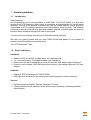
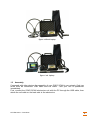
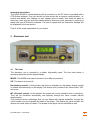
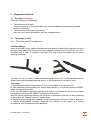
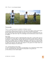
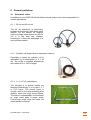
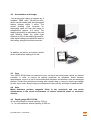
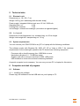
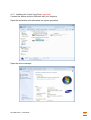
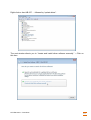
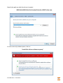
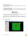
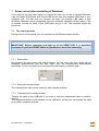
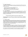
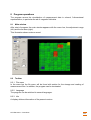
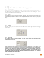
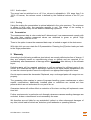
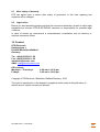
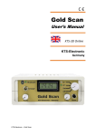
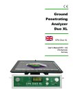
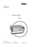
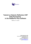
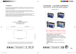
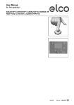
Gold Scan User’s Manual KTS-3D Online KTS-Electronic Germany Table of contents 1 General guidelines................................................................................................. 4 1.1 Introduction ..................................................................................................... 4 1.2 Scope of delivery ............................................................................................ 4 1.3 Assembly ......................................................................................................... 5 2 Electronic unit ........................................................................................................ 6 2.1 The front .......................................................................................................... 6 2.2 The back .......................................................................................................... 7 3 Progress of search ................................................................................................ 8 3.1 Principle (important) ...................................................................................... 8 3.2 The usage of coils ........................................................................................... 8 3.2.1 The 25 cm and 45 cm searchcoil .................................................................. 8 3.2.2 The 1 x 1 m coil (search frame) .................................................................... 9 3.2.3 General advices for the usage ...................................................................... 9 3.3 Precise localisation of metal objects .......................................................... 10 3.4 Search instructions ...................................................................................... 10 3.5 Important informations to the RESET-button ............................................. 11 3.6 The search process ...................................................................................... 11 3.7 Error signals .................................................................................................. 12 4 General guidelines............................................................................................... 13 4.1 Searchcoil choice ......................................................................................... 13 4.1.1 25 cm and 45 cm coil .................................................................................. 13 4.1.2 Cylindric coil (depending on equipment version) ........................................ 13 4.1.3 1 x 1 m PVC searchframe ........................................................................... 13 4.2 Accumulator and charger............................................................................. 14 4.3 Care ................................................................................................................ 14 4.4 Note ................................................................................................................ 14 4.5 Depth gauge GOLD SCAN ............................................................................ 14 5 Technical data ...................................................................................................... 15 5.1 Electronic unit ............................................................................................... 15 5.2 1 x 1 m coil..................................................................................................... 15 5.3 System requirements ................................................................................... 15 6 Computer and start of program .......................................................................... 15 6.1 Software ......................................................................................................... 15 6.1.1 Installing the software ................................................................................. 15 6.1.2 Installing the Virtual Com-Ports (important) ................................................ 16 6.1.3 Program start-up ......................................................................................... 19 6.2 Com-Port setup in program ......................................................................... 19 6.3 Software information .................................................................................... 19 7 Driver set-up (after reinstalling of Windows) .................................................... 20 7.1 The search process ...................................................................................... 20 7.1.1 Start button ................................................................................................. 20 7.1.2 Saving the measurement ............................................................................ 20 7.1.3 Transferring the measured data.................................................................. 20 7.2 7.3 7.4 7.5 System requirements ................................................................................... 21 Licence agreement ....................................................................................... 21 Utilisation clauses ........................................................................................ 21 Disclaimer of liability .................................................................................... 21 8 Program operations............................................................................................. 22 8.1 Main window.................................................................................................. 22 8.2 Toolbar ........................................................................................................... 22 8.2.1 File menu .................................................................................................... 22 8.2.2 Language .................................................................................................... 22 8.2.3 Info.............................................................................................................. 22 8.3 Adjustment range ......................................................................................... 23 8.3.1 Serial interface ............................................................................................ 23 8.3.2 Speed ......................................................................................................... 23 8.3.3 Position ....................................................................................................... 23 8.3.4 Start / Stop .................................................................................................. 23 8.3.5 Audio output................................................................................................ 24 8.3.6 Scaling ........................................................................................................ 24 8.4 Presentation .................................................................................................. 24 9 Warranty ............................................................................................................... 24 9.1 After expiry of warranty ................................................................................ 25 9.2 Legal notice ................................................................................................... 25 10 Contact ................................................................................................................. 25 1 General guidelines 1.1 Introduction Dear customer, we congratulate you on your purchase of Gold Scan. The GOLD SCAN is a high tech product from KTS-Electronic. After years of production and development of various metal detectors, we are in the position to present you the first metal detector, which directly is connectable to a PC to analyze details of your metal findings more precisely. The following informations are very important for gold and treasure seekers, archaeologists and industry because finally treasures thought lost can be recovered. To avoid errors we strongly recommend to read this manual carefully. We wish you great success with your new GOLD SCAN and please to not hesitate to contact us should additional questions arise. Your KTS-Electronic Team 1.2 Scope of delivery Hardware: Search coil 25 cm and 45 cm diameters, incl. telescope bar 1 x 1 m search frame, 8-fold demountable (incl. backpack) Electronics unit with installed lithium ionic accumulator with leather bag with lanyard Powerful quick-charger (2800 MA) with power inverter, car-loading cable and 110 volts adapter Software: Software: KTS-3D software for GOLD SCAN USB stick with software for processing the measuring data on other computers Service: Operating manual English, German, Spanish or French 2 years manufacturer's warranty for the entire scope of delivery (including hardware and software) KTS-Electronic – Gold Scan 4 figure: without laptop figure: incl. laptop 1.3 Assembly Compared with other devices the assembly of your GOLD SCAN is very simple. Only two wires must be connected: USB cable and coil cable - and your unit is operational immediately. First, connect the GOLD SCAN electronics unit with the PC through the USB cable, then attach the coil cable on the back side to the electronics. KTS-Electronic – Gold Scan 5 Important description: The GOLD SCAN is a metal detector with a connection to the PC which is provided with a KTS-Online software. First you should use this device like a common metal detector, i.e. search and identify your findings on your display (kind of metal), then mark the place of discovery. Later you can scan the marked place of discovery more precisely by using your laptop with your KTS-Online software. The use of laptops and the respective settings will be explained in the last section. First of all the exact explanation of your device. 2 Electronic unit 2.1 The front The electronic unit is mounted in a stable, high-quality case. The front side shows 4 operating elements and the digital display. MODE: The MODE knob can be turned to four different positions: Off: The device is turned off. Bat (battery control): In this position the device is switched on, the battery charge control is viewed simultaneously on the display.The device is fully loaded if the value shows “180” and more. MT (All metal search): In this position the metals will not be tested for their conductivity. They will be visualized acoustically and optically through the value number without discrimination. This position has the advantage, that you can detect with highest sensibility; through the value number one can evaluate the depth of the object. The smaller the value number, the deeper the metal object is hidden. The shape of the object can be identified as well. KTS-Electronic – Gold Scan 6 ID (metal discrimination): In this position the discriminator is operable. The metal class number of the found metal object will be calculated and shown on the display. With a little exercise and experience you can declare the metal class through the shown metal class value. The metal class value can be between 0-180 depending on the measured metal class. AUDIO (volume control): With the AUDIO you can regulate the volume. RESET: After pushing the RESET button a automatic zero balance is available. Towards engagement but before the search starts the RESET button must be pushed briefly and then released. This also applies in case the coil should be replaced, so that the new coil can be set and – in addition – should a disturbing error signal occur. FREQ.: After the device was switched to the desired position with the MODE knob and the volume was adjusted the frequency should be regulated in a way, that a slow ticking frequency is audible. A subtle frequency adjustment stands for a stable sound. LED: In the ID position the conductivity of a metal object will be identified. Once the ID LED lights up and the display value stops at a certain place, the metal class can be read off. The conductivity value and the ID LED will be shown as long as the searchcoil will be removed from the metal object. 2.2 The back 1. Socket for coils: The connector for the coil is on the left hand side. The connector plug of the searchcoil has to be plugged into the socket. Before removing the plug, the jack must be pressed, then the plug can be pulled out. The connector is compatible with all GOLD SCAN search coils. 2. Headphone socket: Any commercial headphones with 6.3 mm jack can be plugged in. If you use the headphones, the speaker is turned off. Matching, light weight headphones are provided with the device. 3. Charger socket: To recharge the batteries, insert the plug of the charger into the socket and monitor the loading process. The red LED on the charger signals the recharging process. The green LED shows the end of the recharging process. Charging with the quick charger takes up to 3-4 hours, then the charging plug should be removed. The connector of the charger should be removed before any storage. KTS-Electronic – Gold Scan 7 3 Progress of search 3.1 Principle (important) There are two ways of searching: The scanning of an area First you should only search the plain with the metal detector and mark all possible places of discovery. The scanning of the place of discovery Now you can use the software to scan the marked places. 3.2 The usage of coils 3.2.1 The 25 cm and 45 cm searchcoil The Assembling: Screw the handle on the carbon telescope bar and wrab the cable of the searchcoil around the pipe. Afterwards plug the jack into the proposed connector on the electronic unit. The electronic unit is kept in a special coverbag. The plug should be inserted by the olwer opening of the bag. To swap the coil you need to screw the white plastic screw (incl. nut and distance piece) off and remove the complete holding device. In the following you can switch coils. The usage: 1. The searchcoil should be kept about 2 to 5 cm in parallel to the ground level. 2. After switching and regulating the volume and frequency, you should press the RESET button for balancing the soil. 3. For the soil balance regulatory hold the coil around 5 cm above the ground (on a metal free position) and press the RESET button about 3 seconds. With the ground regulatory balance the influence of minerals in the soil will be neutralized in the search coil, thereby less error signals occur. 4. Repeat the ground regulatory balance at various locations to ensure that the regulatory is always accomplished correctly. Especially by change of soil layers, e.g. during excavations, this process should be repeated. KTS-Electronic – Gold Scan 8 3.2.2 The 1 x 1 m coil (search frame) The assembly: The 1x1 m search framework is available in 2 different versions. 1. The search cable is firmly connected in a PVC pipe (8-fold split): In this case the pipes must be simply sticked together and be worn with the two included hanging belts. 2. The search cable is not connected to the pipes: In this case you should first attach the PVC pipes to the cable with a tape. The advantage is that this alternative version is easier to transport. The usage: The search framework consists of lightweight plastic pipes and a 4 meter cable, that can be attached in or on the pipes. It is best suited for the search for larger objects, which are suspected in a large-scale area, because with the help of 2 persons you can gain a faster and more convenient result. An additional advantage of this large coil is the fact that smaller disturbing metal parts do not appear. The searchcoil can be carried between 20-50 cm above the ground. The higher the distance to the ground, the lesser small and medium-sized metal parts can be notified. 3.2.3 General advices for the usage To make a speedy swing of the search coil dispensable, we’ve designed the GOLD SCAN for you. Just hold down the search probe flat and parallel to the ground, and you can dictate your own search speed. KTS-Electronic – Gold Scan 9 After turning on the device, press the RESET button for a brief moment and regulate the FREQ. regulator until a slow ticking signal is hearable. This signal is acoustically similar to a seconds counter. With each new setting press the RESET button to set the zero adjustment. With the knob AUDIO set the desired volume. There are 2 search methods to choose from: MT. search method: Therefore turn the MODE control on the position MT. This search system shows all metals. With the ALLM. search method you draw more power from your device, however, there is no metal discrimination possible. ID search method: For this purpose set the MODE control to the position ID – the metal discrimination takes place. Once the ID-LED lights, a value will be shown on the display. Aluminium approx. Copper approx. Iron approx. Gold approx. 20 – 40 40 – 60 60 – 80 100 and higher. 3.3 Precise localisation of metal objects Your GOLD SCAN works with the pulse induction searching system and is able to detect without setting the searchcoil in motion. With approaching the searchcoil to a metal object the frequency of the sound increases. As soon as the searchcoil is exactly positioned over the object, the highest tone is reached. With this method not only the exact find spot of the object will be located but the shape of the item can be identified through the sound continuity also. For example, a long-lasting high tone stands in longitudinal direction for a narrow object, e.g. a pipe. A high tone in any direction indicates a circular object. 3.4 Search instructions Please be sure that you do not carry metal objects with you during the search process. This could cause a wrong adjustment when pushing the RESET key and can produce false indicator effects whilst the search. In addition, this can cause a wrong discrimination or metal distinction. During the search, make sure that the tone remains constant, otherwise a wrong adjustment by magnetic fields may occur. Especially when you search with the 1 x 1 m coil (search framework) be certain that – should a instable tone appear - the RESET key is pressed. This must be accomplished in order to prevent unwanted interferences by geomagnetism. Strongly magnetized soils affect large search coils (searchframe) more than small searchcoils. Therefore be certain, when searching with the large coil, that the searchcoil is kept approx. 15-50 cm (depending upon need) parallel to the soil and avoid jerky movements. KTS-Electronic – Gold Scan 10 3.5 Important informations to the RESET-button The function of the RESET button is very significant and it should be pressed after each of the following changes. 1. 2. 3. 4. After every activation of the metal detector After every change of the mode function After each exchange of the search coil During the search, if the sound becomes unstable due to bad ground conditions or geomagnetism. 3.6 The search process To create the search more targeted and successfully – especially before the excavation – please pay attention to the following: 1. 2. 3. 4. Change in the tone (frequency) Intensity of the sound Duration of the clay The value (digital display) The change of the tone is the first sign for the detection of a metal object. Before the excavation, however, different factors should be analyzed and the own search experience be pulled to the assistance. The more intensive the tone, the nearer the position and larger the metal object. While the high search tone is audible, the searchcoil should be moved in the close environment to determine the approximate form of the metal object. The pointer excursion works in the ALL METALS position exactly the same as the tone. Simultaneous observation of tone and display leads to a better analysis of the found object. After size and – with the simultaneous movement of the search coil – probable form of the object where determined (conditional upon the intensity of the tone and the clarity of the display), one can start with the conductive recognition and metal distinction. For the identification of the metal object the DISC position should be selected. After activation of the RESET key and the renewed FREQ. attitude hold the search coil over the soil and observe the display. Your GOLD SCAN has a metal distinction. In addition the inserted microprocessor computes the conductivity of the metal objects and indicates them on the digital display. The GOLD SCAN was developed in such a way that the necessity of swivelling the searchcoil is not given. During the depth detection this proves as particularly helpful. For the identification of a metal object a weak tone is insufficient. The requirement of a signal with high intensity is necessary so that the conductivity of a metal can be computed. As long as the searchcoil is located on the metal object, the conductance number is stored and indicated. We recommend to locate primarily the findings with the sensitive search mode ALLM. and – only if a clear acoustic signal is to be heard – switch to the DISC mode afterwards. KTS-Electronic – Gold Scan 11 In addition, hold the searchcoil in a constant height over the soil and press the RESET key for approx. 2 seconds. Then again move the searchcoil over the located metal object. As soon as the acoustic signal reached its highest intensity, the metal will be shown on the display. Compare the indicated conductance with the specified values on page 9 in order to determine the kind of metal you have found. The indicated values are appoximate values, which can be completed by your own search experience in your search area. light metal (e.g. aluminum) copper gold ca. ca. ca. 40 110 150 and over Please note that size and shape of the found objects will influence the measured data. Your own search experience will help you to identify your discovery as closely as possible. NOTE: To avoid wrong conductivity values it is absolutely necessary to RESET the soil balance by using the RESET button to renew the soil balance attitude after a mode change. When activating the RESET key you have to be sure, that no metal parts are contained in the soil. 3.7 Error signals In line with the development of your GOLD SCAN great emphasis was placed on stability and the avoidance of incidences. Despite the multiplicity of filters and modulators it is unfortunately possible that certain soil conditions cause disturbances, which can effect your measured values. Apart from a wrong soil balance attitude incorrect signals can occur by following effects: 1. Ferric oxide: Through magnetic ferric oxide soils the conductance of the located metal can comprehend falsified data. 2. Anomaly effects lead to the fact that large iron metals are indicated as precious metal. 3. Small parts of bronce partially may be indicated as iron, the accuracy of the measured values is therefore ensured starting from 5 x 5 cm in dimension. 4. The measured values can be falsified, because in the proximity of the located metal object other metal parts are existent. 5. Strongly magnetic interference fields within residential areas and in the proximity of ground cables can influence the measured values especially during the utilization of the large search coil. 6. Disturbances often occur in the peripherals of radio stations. 7. Strongly magnetic fields, particularly in the proximity of high voltage masts, can cause disfunctions. KTS-Electronic – Gold Scan 12 4 General guidelines 4.1 Searchcoil choice In addition to your GOLD SCAN we deliver several search coils, each responsible for certain applications. 4.1.1 25 cm and 45 cm coil The 25 cm searchcoil is particularly suitable for the search after small metal objects. For the search for medium sized and large metal objects the 45 cm coil is in the best way suitable, furthermore it offers the advantage of a more efficient search. 4.1.2 Cylindric coil (depending on equipment version) Especially in areas the cylindric coil is applicable by its dimensions of 5 x 20 cm. The probe is supplied alternatively with cables of 5 or 10m in length. 4.1.3 1 x 1 m PVC searchframe The provided 4 m special cables are fastened alternatively in or to that 1 x 1 m PVC frame. The search frame is usually used for the deep sounding after medium sized and large metal objects. The frame is indispensably for the search for huge metal parts in larger areas. Furthermore small scrap iron parts will automatically be filtered. KTS-Electronic – Gold Scan 13 4.2 Accumulator and charger The strong pulse rating is supplied by a installed 2800 mAh Lithium-ion-accu, which can be loaded with the high-speed battery charger within 3 hours. The actual working time amounts to, depending upon coil size and usage of headphones, approx. 4-8 hours. The loading procedure is indicated by the red light emitting diode, the green light shows the end of the loading procedure. After each loading procedure the lead for the battery charger should be removed. In addition, we deliver an inverter module which enables the loading in the car. 4.3 Care Your GOLD SCAN does not need much care, yet there are some points, which you should consider, in order to receive its optimal readiness for operation. Avoid extreme temperatures, since it is not to be excluded that electronic construction units are damaged thereby. Protect the electronics housing with a plastic bag in case you should get caught by rain, fog or dust. Always keep your equipment clean and dry and wipe off sand and dirt. 4.4 Note Metal detectors produce magnetic fields in the searchcoil and can cause disturbances in the closer environment of certain industrial plants or electronic devices. 4.5 Depth gauge GOLD SCAN 45 cm coil maximum search capacity 270 cm 1 x 1 m coil maximum search capacity till 500 cm KTS-Electronic – Gold Scan 14 5 Technical data 5.1 Electronic unit Dimensions ca.: 18 x 22 x 7 cm Weight: 1450 g (incl. leatherbag with shoulder strap) Power supply: integrated Lithium-ionic accu 12 Volt / 2800 mA Operating time: ca. 4-8h Loading time: maximal 3-4h car-recharger: external car-recharger (connection at cigarette lighter) 5.2 1 x 1 m coil Dimensions: 8-fold fragmented, incl. transport bag, ca. 60 cm length Weight: total weight incl. transport bag ca. 1,2 kg 5.3 System requirements You can connect your GOLD SCAN to any PC or Laptop with the following conditions: The software works with Windows 98, 2000, NT, XP or Vista or WIN 7. As minimum requirements for the meaningful operation the PC should have following equipment: Processor with a clock frequency from 1000 MHz or more Hard drive with about 10 .. 20 MB free space Graphic card with a minimum resolution of 800 x 600 points USB interface to connect the external measuring hardware A special computer is not necessary. You can use your own PC or Laptop for this device. 6 Computer and start of program 6.1 Software 6.1.1 Installing the software Please copy the software from the USB-stick on your Laptop or PC KTS-Electronic – Gold Scan 15 6.1.2 Installing the Virtual Com-Ports (important) Connect the device and the USB-stick with your computer Open the workstation and afterwards the system properties. Open the device manager KTS-Electronic – Gold Scan 16 Right click on item HB 627 … followed by “update driver”. The next window directs you to “Locate and install driver software manually.” – Click on this item. KTS-Electronic – Gold Scan 17 Specify the path on which the driver is located - USB-Stick/USB-Stick für Kunden/Virtueller USB-Treiber neu. In case a security window opens, click on “Install this driver software anyway” KTS-Electronic – Gold Scan 18 6.1.3 Program start-up Open the software on KTS-Online.exe Please note that the minimum resolution is 800x600, because otherwise important functions are not visible. 6.2 Com-Port setup in program Under the heading "serial interface“, you first must set the COM-port in device manager. In our example it was the COM-port number 4. Click on search first, because only the available Com ports can be selected. ill: serial interface KTS-Online Only the active COM-ports can be selected, which means the GOLD SCAN must be connected at least 1 minute and both green LEDs must light. In exceptional cases, it may be possible that the USB interface is not activated. Then disconnect the USB connection. Wait 2 minutes and connect it again. Now the COM-port is active. 6.3 Software information Already during recording the software shows the measured data in 3D representation. ill. measured data KTS-Electronic – Gold Scan 19 7 Driver set-up (after reinstalling of Windows) If you want to use any other laptop to connect the main unit or had to reinstall Windows copy the folder KTS-Online and Virtual USB drivers from the supplied USB-stick to your computer first. The first time you connect the main unit through USB cable, a new Windows Hardware will be recognized. Now the Windows Hardware Wizard starts. Click on browse, choose the folder Virtual USB driver and go to OK. The computer installs the first driver. 7.1 The search process During control of the ground, you can commence with different search modes. IMPORTANT: Before searching and light up of the RESET-LED it is absolutely necessary to push the RESET button to guarantee an error-free measuring. 7.1.1 Start button By pressing the start button the search begins. On the sreen the first results will be displayed 2-dimensional until the path ends, then the measurement automatically terminates. For the next path you must press the start button to operate again. 7.1.2 Saving the measurement The measurement data can be stored for later analysis at home. 7.1.3 Transferring the measured data Transfer the data on the USB-stick if you wish to view the measurment data on another monitor. The complete software is pre-installed on the USB-stick, so that you can transfer the data to any other computer and edit. KTS-Electronic – Gold Scan 20 7.2 System requirements The program is a 32-bit application that operates under Windows 98, 2000, NT, XP, Vista or WIN 7. The minimum conditions for the proper operation should be equipped with following requirements: Processor with a pulse frequency of 1000 MHz or more Hard drive with approx. 10 .. 20 MB free space Graphic card with a minimum resolution of 800 x 600 points USB interface to connect the external measuring hardware 7.3 Licence agreement The program KTS-Online as well as the entire accompanied electronic or printed documentation is subject to the copyright of the company KTS-Electronic. If parts of the present license regulations should show alterations or expansions in comparison to license regulations for former program versions, the current license regulations are valid with beginning of the effective date. The present license regulations come into force at May 1st, 2007. Through the utilization of the software, the user agrees to the present license regulations. For each incidence of violation of the terms of license the right of utilization automatically becomes void. 7.4 Utilisation clauses After full payment of the invoice amount the customer is allowed to a not-exclusive right of usage of the program listed in the bill. This right is restricted to the owner of the original software. Consequently, the software can be used only on one single computer system at the same time. All present and future copyrights and/or industrial protection rights of the provided programs and of all programs derivative from it, program modules or in this context produced records remain at KTS-Electronic. 7.5 Disclaimer of liability The present program was tested carefully, nevertheless mistakes are not to be excluded. No guarantee is adopted for the usability of the program to a certain purpose. Especially, no liability is adopted for consequential damages as well as profit and asset losses, that could result from the application of the program as well as the affiliated documentation. Price variations as well as alterations of each type regarding the software and the documentation must remain reservations and must not need separate notification. KTS-Electronic – Gold Scan 21 8 Program operations The program serves the visualisation of measurement data in colored, 3-dimensional representation, in particular the ad of magnetic field data. 8.1 Main window After start of program the main window appears with the menu bar, the adjustment range (left) and the ad-area (right). This illustration shows a demo record. 8.2 Toolbar 8.2.1 File menu In the menu bar the file menu will be found with entries for the storage and reading of measurement files. In addition, the program can be terminated. 8.2.2 Language The program can be switched to several languages. 8.2.3 Info A display delivers information of the present version. KTS-Electronic – Gold Scan 22 8.3 Adjustment range All settings will be saved and are available on the next program start. 8.3.1 Serial interface Here you can choose the COM-port for the connection to the measurement hardware. In this list only the present COM-port will be shown. The number of the COM-ports can be read out in the Windows Device Manager. 8.3.2 Speed The measuring speed is devided into three velocities. The movement on the paths must comply with your speed. A switch is also compatible with the function keys [F2], [F3] and [F4]. 8.3.3 Position The 3D display can be rotated and tilted. The center button [0] resets to the origin presentation. 8.3.4 Start / Stop By pressing [Start] the search begins. With the button [Stop] you can interrupt the measurement at any time. At the beginning of the measuring process a countdown takes place. In the display area numbers from 3 to 0 will be shown. The figures are accompanied by short audio signals. After the START display the actual measurement starts. The probe must be moved from left to right. At the end of the path the audio signal is repeated. The probe must now be moved a little forward, the next path requires a movement from right to left. The recording stops automatically after the last path. KTS-Electronic – Gold Scan 23 8.3.5 Audio output The sound can be switched on or off. Your volume is adjustable in 10% steps from 0 to 100%. Of course, the volume control is defined by the individual volume of the PC you use. 8.3.6 Scaling Using the scaling the presentation is optimal adjusted in the color spectrum. The minimum is shown in blue color, the maximum appears in red. The usage of the scaling is recommended particularly for few destinct measuring dynamics. 8.4 Presentation The measurement data is color-coded and 3-dimensional. Low measurements comply with the color blue, medium measured values are attributed to green or yellow. High measurements are shown in red. There is the option to save the measured data resp. to looked on again in the data menu. With right click you can rotate the 3-D presentation. Pressing the [0] button leads you back to the origin presentation. 9 Warranty According to the following conditions (see below) we remedy deficiencies free of charge, if they are evidently based on manufacturing errors or defects and are reported to us immediately after assessment of damage within 24 months after delivery to the ultimate buyer. Defective parts will be repaired gratuitous or will be replaced by efficient parts of our choice. KTS reserves the right to exchange a device by an equal valued replacement unit in case the returned product cannot be required in an appropriate budget time frame. On-site repairs cannot be demanded. Replaced, resp. exchanged parts will merge into our property. The guarantee claim expires in cases of improper handling, gross carelessness or when repairs, modifications, additionally installed parts or extentions are carried out from persons which are not authorized on our part to do so. Guarantee claims will neither effect an extention of the term nor they will implement a new time limit. Further requirements, in particular such through extraneous causes resulting damages are excluded, unless a commitment is not necessarily the case. We therefore are not liable for any accidential, indirect or other subsequent damages of any kind, which lead to limited use, data loss, profit setbacks or operating failures. KTS-Electronic – Gold Scan 24 9.1 After expiry of warranty KTS can agree upon a service after expiry of guarantee. In this case repairing and shipment will be charged. 9.2 Legal notice Before you start searching please note that the monument protection as well as other legal standards are relevant. KTS-ELECTRONIC assumes no responsibility for possible legal violations. In case of doubts we recommend a comprehensive consultation with an attorney or national monument offices. 10 Contact KTS-Electronic Kurhessenstr. 1 D-64546 Mörfelden-Walldorf Germany Tel: +49-(0)6105 9111-50 Fax: +49-(0)6105 9111-55 www.kts-electronic.com eMail: [email protected] Office hours: Mondays – Thursdays: Fridays: 9:00 am to 16:30 pm 9:00 am to 16:00 pm Copyright: KTS-Electronic, Mörfelden-Walldorf/Germany, 2010 The right to reproduction or the disposal of graphics and/or texts of this publication is without autor’s explicit consent not allowed. KTS-Electronic – Gold Scan 25