1
HS2016/2032/2064/2128 Alarm Panel
V1.1 User Manual
WARNING: This manual contains information on limitations regarding product use and function and information on the limitations as to liability of the manufacturer. The entire manual should be carefully read.
Table of Contents
1.0 Quick Reference
2.0 Understanding your Keypad
2.1 Icon and LED Keypad Symbols
2.2 Keypad Models
3.0 Securing the Premises
3.1 Arming the System
3.1.1 Arming the System (Infinite Exit Delay)
3.1.2 Away Arming the System with the Keypad
3.2 Stay Arming the System with the Keypad
3.2.1 Silent Exit Delay
3.3 Night Arming the System with the Keypad
3.4 No-Entry Arming
3.5 Leaving when the System is Already Armed - Quick Exit
3.6 Arming the System with a 2-way Wireless Key
3.7 Bypassing Zones
3.7.1 Additional Bypass Features
3.8 Bypass Groups
3.9 Arming Errors and Exit Faults
3.9.1 Arming Errors
3.9.2 Audible Exit Faults
3.9.3 To Correct an Exit Fault
3.10 Disarming the System
3.10.1 Disarming Error
4.0 The PowerSeries Neo Security System
4.1 General System Operation
4.2 Carbon Monoxide Detection
4.3 Fire Detection
4.4 Testing your System
4.5 Monitoring
4.6 Maintenance
5.0 Emergency Keys
5.1 Alarms
5.1.1 Fire Alarm
5.1.2 Carbon Monoxide Alarm - 4 beeps, long pause, 4 beeps
5.1.3 Intrusion (Burglary) Alarm - Continuous Siren
5.1.4 Alarm Cancel Window
5.1.5 Viewing Alarms in Memory
5.1.5.1 Alarm Messages
5.2 Resetting Smoke Detectors
6.0 Wireless Keys and other Devices
6.1 Using 2-way Wireless Keys
6.1.1 PG4929/PG8929/PG9929
6.1.2 PG4939/PG8939/PG9939
6.2 Using Proximity Tags
6.3 SMS Command and Control
6.3.1 Using the Keypad to Lookup the Number to Call for SMS Commands
6.3.2 Sending SMS Commands to your System
6.3.3 SMS Commands
6.3.4 SMS Responses from your System
7.0 Managing Users
7.1 Access Code Types
7.1.1 Adding, Changing and Deleting Access Codes
7.1.2 Enrolling and Deleting Proximity Tags
7.1.3 Naming a User
7.1.4 Assigning a Partition to a User code
7.2 Configuring additional User Options
8.0 User Functions
8.1 Event Buffer
8.2 Setting the Time and Date
8.3 Enabling/Disabling the Auto Arm/Disarm Feature
8.4 Setting the Auto Arm Time
8.5 Allowing the Installer to Service your System Remotely - DLS
8.6 User Callup
8.7 Late to Open
8.8 Changing the Brightness of the LCD keypad
8.9 Changing the Contrast of the LCD keypad
8.10 Setting the Buzzer volume
8.11 Setting the Voice Prompt volume
8.12 Setting the Voice Chime volume
8.13 Resetting the System
-2-
4
6
6
7
8
8
8
8
9
9
9
10
10
11
11
11
13
13
13
14
14
14
14
15
15
15
15
15
15
16
17
17
17
17
17
17
18
18
18
19
19
19
19
19
19
19
20
20
21
22
22
23
23
24
24
24
25
25
25
25
25
26
26
26
27
27
27
27
27
28
Table of Contents
8.13.1 Engineer's Reset
8.13.2 Remote (Anti-code) Reset
8.14 User's Walk Test
8.14.1 Full System Walk Test
8.15 Trouble Conditions
9.0 Managing Partitions
9.1 Partitions
9.1.1 Single Partition Operation
9.1.2 Loaning a Keypad to Another Partition
9.2 Fire and CO Zone Types
10.0 Additional Features
10.1 Turning the Chime ON/OFF
10.2 Audio Verification
10.3 Visual Verification
10.3.1 System Lockout due to Invalid Attempts
10.4 Command Outputs
10.5 Burglary Verification
10.6 Swinger Shutdown
10.7 Call Waiting
10.8 Fire Alarm Verification
11.0 Regulatory Agency Statements
11.1 CE Compliance Statement
11.2 EN50131 Compliance Statement
11.3 UK Compliance Statement
12.0 Installer Warning
13.0 Safety Instructions
13.1 Regular Maintenance and Troubleshooting
13.1.1 Cleaning
13.1.2 Troubleshooting
13.1.3 Applicable Models
14.0 EULA
15.0 Locating Detectors and Escape Plan
15.1 Smoke Detectors
15.2 Fire Escape Planning
15.3 Carbon Monoxide Detectors
16.0 Reference Sheets
16.1 System Information
16.2 Service Contact Information
16.3 Access Code and Sensor/Zone information
28
28
28
28
29
32
32
32
32
32
33
33
33
33
33
33
33
34
34
34
35
35
35
35
36
38
38
38
38
38
39
41
41
41
42
43
43
43
44
-3-
Chapter 1
1.0 Quick Reference
The PowerSeries Neo Alarm System uses shortcut keys to access options or features on all models of keypads. When using an
LCD keypad, the PowerSeries Neo Alarm System additionally uses a menu based navigation system. The scroll keys can be used
to [Scroll] through the list of options contained within the current menu. For more information on keypads see: 2 “Understanding
your Keypad”. Lookup detailed information on any of the listed actions using the accompanying Section number.
Note: Some features must be enabled by installer.
Note: Bypass Groups are not permitted in UL listed installations.
Note: [*] - If configured by installer.
Status
Function Keys
Lights
Function Status Emergency Emergency
Keys
Lights Keys
Keys
Ready - Indicates system normal. Must be on to arm system. All zones
must be secured or bypassed and the system disarmed for this light to
activate.
Stay
Arm
Fire Alarm
Armed- Indicates system is armed. If the Ready light and the Armed
light are both on, an Exit Delay is in progress.
Away
Arm
Medical
Alarm
Trouble - On indicates a system malfunction or tamper. Flashing indicates that the keypad has a low battery condition. Follow the instructions
displayed or enter [*][2] to view trouble. Correcting the trouble turns
off the indicator.
Chime
Panic Alarm
AC Power - Indicates AC Power is present. The AC Power light will
turn off when AC is absent.
Reset Sensors
Quick
Exit
Action
Press
Section
Arming and Disarming
Away Arm
for 2 seconds + [Access Code*]
3.1.2
Stay Arm
for 2 seconds + [Access Code*]
3.2
Night Arm
When armed in stay mode [*][1] + [Access 3.3
Code*]
Disarm
[Access Code]
3.1
No-Entry Arming
[*][9] + [Access Code*]
3.4
Quick Arm/Quick Exit
[*][0]
3.5
Abort Arming Sequence
[Access Code]
Bypassing - All bypass commands begin with [*][1] + [Access Code*]
Bypass Individual Zones
[3 Digit Zone #]
3.7.1
Bypass All Open Zones
[9][9][8]
3.7.1
Recall Last Bypass
[9][9][9]
3.7.1
Clear Bypass
[0][0][0] OR [Scroll] Bypass Options + [*] 3.7.1
+ [Scroll] Clear Bypasses + [*]
Program Bypass Group
[3 digit zone #s] + [9][9][5] OR [3 digit
zone #s] + [Scroll] Bypass Options + [*] +
[Scroll] Prg Bypass Group + [*]
Load Bypass Group
[9][9][1] OR [Scroll] Bypass Options + [*] 3.8
+ [Scroll] Bypass Group + [*]
3.8
Common Functions
Set Time and Date
[*][6] [Master Code] + [0][1]
8.2
Turn Chime ON/OFF
[*][4] + [Access Code*] OR
10.1
Change Brightness
Change Contrast
[*][6] [Master Code] + [1][2] +
[*][6] [Master Code] + [1][3] +
-4-
8.8
8.8
Chapter 1
Action
Press
Add/Delete User
[*][5] + [Master Code] + [Access Code] + 7.0
1
Reset Smoke Detectors
View Troubles
View Alarms
Perform System Test
Buzzer Volume
Section
5.2
OR [*][7][2]
8.15
[*][2] + [Access Code*] +
5.1.5
[*][3] + [Access Code*] +
[*][6] + [Master Code] + [0][4] +
[*][6] + [Master Code] + [1][4] +
-5-
4.4
8.10
Chapter 2
2.0 Understanding your Keypad
The PowerSeries Neo Alarm System supports a variety of wireless, hardwired and proximity sensor LCD, LED and Icon keypads.
All keypads come equipped with the LED status lights described in section 1 "Quick Reference". HS2LCD series keypads display
system messages on their LCD screen. HS2ICN series keypads display messages, as described in the following section. HS2LED
series keypads display messages via a series of numbered LEDs, as described in the following section. All keypad versions will
have a solid blue LED bar that is always on steady except when, if enrolled, a proximity tag is presented to and successfully read
by the keypad.
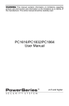
2.1 Icon and LED Keypad Symbols
HS2ICN Series
5
9
HS2LED Series
1
2
3
4
6
9
15
5
16
7
17
14
12
7
11
8
10
6
13
1.
Clock Digits 1, 2
These two 7 segment clock digits indicate the hour digits when the local clock is active. Digit
2 is also used to identify the zone number as the 1 when the zone number is 100 or higher and
the OPEN or ALARM icons are active.
2.
: (Colon)
This icon is the hours/minutes divider and will flash once per second when the local clock is
active.
3.
Clock Digits 3, 4
These two 7 segment displays are the minute digits when the local clock is active. The digits
3 and 4 are used to indicate the zone number for open zones or alarm in memory. These two
digits combined with the clock digit 2, scroll one zone per second from the lowest number to
the highest, when scrolling through zones.
4.
1 to 8
These numbers identify troubles when [*][2] is pressed.
5.
Memory
Indicates that there are alarms in memory.
6.
Bypass
Indicates that there are zones bypassed.
7.
Program
Indicates that the system is in Installer or User's programming, or that the keypad is busy, and
the LED will flash in cadence of 250ms ON and 250ms OFF. If Access Code is required,
while accessing star menus, this LED is ON and solid to indicate that the code is required.
8.
Away
Indicates that the panel is armed in the Away Mode.
9.
Fire
Indicates that there are fire and/or CO alarms in memory.
10.
Stay
Indicates that the panel is armed in the Stay Mode.
11.
Chime
This icon turns on when the Chime function key is pressed to enable Door Chime on the system. It will turn off when the chime function key is pressed again to disable Door Chime.
12.
OPEN
This icon is used with clock digits 1 and 2 to indicate activated zones (not alarm) on the system. When zones are opened, the OPEN icon will turn on, and 7 segment displays 1 and 2
will scroll through the violated zones.
13.
AC
Indicates that AC is present at the main panel.
14.
System Trouble
Indicates that a system trouble is active.
15.
Night
Indicates that the panel is armed in the Night Mode.
16.
Ready Light (green)
If the Ready light is on, the system is ready for arming. If the toggle of the Ready LED
flashes for Force Arming enabled, the LED flashes with force armable zones open on the
partition.
17.
Armed Light (red)
If the Armed light is on, the system has been armed successfully.
Note: For UL listed installations, zones can only be bypassed manually.
-6-
Chapter 2
2.2 Keypad Models
Note: In the following list if x = 9 (the system operates in 912-919MHz), x=4 (the system operates in 433MHz band) or x=8 (the
system operates in 868MHz band). Only models operating in 912-919MHz band are UL/ULC listed.
HS2LCD
Alphanumeric LCD keypad
HS2LCDP
Alphanumeric LCD keypad with Prox. Tag support
HS2ICN
Icon keypad
HS2ICNP
Icon keypad with Prox. Tag support
HS2LED
LED keypad
HS2LCDRFx
Alphanumeric LCD keypad with wireless receiver
HS2LCDRFPx
Alphanumeric LCD keypad with wireless receiver and Prox. tag support
HS2ICNRFx
Icon keypad with wireless receiver
HS2ICNRFPx
Icon keypad with wireless receiver and Prox. tag support
HS2LCDWFx
Wireless Alphanumeric LCD keypad
HS2LCDWFPx
Wireless Alphanumeric LCD keypad with Prox. Tag support
HS2LCDWFPVx Wireless Alphanumeric LCD keypad with Prox. Tag support & Voice Promp
HS2TCHP
Touchscreen keypad. For additional information, refer to the HS2TCHP Touchscreen User Manual; part #:
29009060R001.
Note: For systems compliant with EN50131-1 and EN50131-3 the HS2LED keypad shall be used in conjunction with an LCD type
keypad (HS2LCD(P) or HS2LCDRF(P)8 or HS2LCDWF(P)8) in order to be able to review logged events and also to allow overriding of conditions that inhibit setting of the alarm system. The HS2LED keypad alone cannot support these functions.
-7-
Chapter 3
3.0 Securing the Premises
The PowerSeries Neo provides multiple arming modes as described below:
Away mode
Use when no one in your household will be home. Away mode activates all perimeter and interior sensors
in the alarm system.
Stay mode
Use this mode when you are staying home, but expect someone to use the entrance door later. Stay mode
partially activates your alarm system by arming all perimeter sensors and bypassing all interior sensors.
Night mode
Use when you want the perimeter and interior armed but would like to allow limited movement in your
house without activating the alarm. (e.g., disable motion sensors in an area containing bedrooms and a
washroom). Night mode is similar to Stay mode but only bypasses internal sensors configured as Night
Zones.
Note: Verify with your alarm company which modes are available on your system. For SIA FAR listed panels, the Stay Arming
Exit Delay will be twice as long as the Away Arming Exit Delay.
Depending on your system configuration, there are multiple methods you can use to arm your system.
You can arm the system using a:
l
Keypad
l
2-way wireless key
See also:
l
Silent Exit Delay
3.1 Arming the System
The PowerSeries Neo system can be armed using a keypad, a 2-way wireless key or a proximity tag.
3.1.1 Arming the System (Infinite Exit Delay)
In an attempt to reduce false alarms, your system is designed to notify you of an improper exit when arming the system. When
using the Push to Set, or Final Door Set feature, attempting to arm your system will start an infinite exit delay. The keypad will
sound a beep once per second. When you have opened and closed the final exit door, or after pressing the Push to Set button, the
exit delay will be reduced to a programmable value, which is typically 10 seconds, after which the alarm will complete the setting.
The panel used this time period to allow time for the detectors on the system to return to their normal state. When this time
expires, the system checks for detectors/windows/doors that may be open. If any of these are open, the panel will cancel the arming. If this occurs, you must re-enter the premises, check the system, close any open zones, and then attempt to arm again.
3.1.2 Away Arming the System with the Keypad
Away mode activates the complete alarm system by:
l
Arming all perimeter sensors.
l
Arming all interior sensors.
To Arm the System in Away Mode
LCD Display
1.
Ensure all windows and doors are closed and that the Ready indicator is on.
Date Time
JAN 02/13 2:06a
2.
To arm using the Away key
, press and hold the Away key for 2 seconds and, if
required, enter your [access code] or present your proximity tag.
System is
Ready to Arm
OR
then
To Quick Arm the system press [*][0].
Present Tag or
Enter Code
3.
If zones have been bypassed, ICN or LED keypads bypass LED
will light and
the bypassed zones #s will be shown. On an LCD keypad a warning appears.
* Warning *
Bypass Active
4.
After successfully initiating the arming sequence the:
Exit Delay in
Progress
l
l
l
l
l
5.
Armed
indicator turns on.
Ready
indicator remains lit.
Exit Delay timer begins counting down.
Keypad beeps six times, continues beeping once per second until beeping rapidly
in the final ten seconds.
The system may be configured to have a persistent exit delay that only ends when
the exit door is opened and closed, or when a button is pressed outside the protected premises.
To cancel the arming sequence, enter your [access code] or present your proximity
tag to the keypad reader.
-8-
System Disarmed
No Alarm Memory
Chapter 3
6.
Once the exit delay timer expires, thereby arming the system, the:
l
l
l
Ready indicator turns off.
Armed indicator remains on.
Keypad stops sounding.
System Armed
in Away Mode
Note: The installer configures the exit delay timer and whether or not an access code is required for arming the system.
3.2 Stay Arming the System with the Keypad
Stay mode partially activates your alarm system by:
l
Arming all perimeter sensors.
l
Bypassing all interior sensors.
To Arm the System in Stay mode
LCD Display
1.
Ensure all windows and doors are closed and that the Ready indicator is on.
Date Time
JAN 02/13 2:06a
2.
Press and hold the Stay key
for 2 seconds and, if required, enter your [access code]
or present your proximity tag. Do not leave the premises.
System is
Ready to Arm
then
Enter Your
Access Code
3.
If zones have been bypassed, ICN or LED keypads bypass LED
will light and the
bypassed zones #s will be shown. On an LCD keypad a warning appears
* Warning *
Bypass Active
4.
After successfully initiating the arming sequence the:
Exit Delay in
Progress
l
l
l
Armed
indicator turns on.
Ready
indicator remains lit.
Exit Delay timer begins counting down.
5.
To cancel the arming sequence, enter your [access code] or present your proximity tag.
System Disarmed
No Alarm Memory
6.
Once the exit delay timer expires, thereby arming the system, the:
l
Ready
indicator turns off.
System Armed
in Stay Mode
l
l
Armed
indicator remains on.
Bypass or system indicator activates.
3.2.1 Silent Exit Delay
If the system is armed using the Stay key
or the No Entry Arming method [*][9]:
l
The warning beep is silenced.
l
The exit time is doubled for that exit period only (CP-01 versions only).
Note: For non CP-01 versions, Standard Exit Time is used.
3.3 Night Arming the System with the Keypad
Night mode partially activates the alarm system by:
l
Bypassing all internal sensors configured as Night zones.
l
Arming all perimeter sensors.
l
Arming all other internal sensors.
Arming the system in Night mode is possible after the system has first been armed in Stay mode and [*][1] is pressed at the
keypad. The keypad can also be configured with a function key to arm the system in Night mode. To access armed interior areas
when the system is armed in Night Mode, you must disarm the system.
Note: Ensure that your installer has provided you with a list identifying all programmed night zones. Your installer can configure a
function key to arm the panel in Night mode without the system already being armed in Stay mode.
-9-
Chapter 3
To Arm the System in Night mode
1.
LCD Display
If configured, press and hold the Night Arm key for 2 seconds.
OR
2.
Once the system is armed in Stay mode (Armed
press [*][*].
indicator is on) at any keypad
Date Time
JAN 02/13 2:06a
then
Press (*) for <>
Interior Arm
OR
press[*][1].
3.
If required, enter your [access code]. All interior zones will now be armed, except
for devices programmed as Night Zones.
l
The Night mode
icon turns on.
Present Tag or
Enter Code
then
Interior Has
Been Armed
To gain access to interior areas that are armed during Night mode disarm the system by entering your [access code].
3.4 No-Entry Arming
No-Entry Arming arms the system in Stay mode by:
l
Removing the Entry Delay from all configured zones.
l
Arming all perimeter sensors.
l
Bypassing all interior sensors.
An entry through any zone will create an instant alarm.
To No-Entry Arm the System
LCD Display
1.
Check that the Ready indicator
is on and your system is ready to be armed.
2.
Press [*][9] and, if required, enter your [access code].
Present Tag or
Enter Code
3.
If zones have been bypassed, ICN or LED keypads bypass LED will light and the
bypassed zones #s will be shown. On an LCD keypad a warning appears.
* Warning *
Bypass Active
Date Time
JAN 02/13 2:06a
then
4.
After successfully initiating the arming sequence the:
l
Armed light flashes as a reminder that the system is armed and has no entry delay.
l
Keypad sounds fast beeps.
l
Keypad displays “Exit Delay in Progress”.
Armed With No
Entry Delay
5.
To cancel the arming sequence, enter your [access code] or present your proximity
tag.
System Disarmed
No Alarm Memory
6.
Once the exit delay timer expires, the system is armed.
System Armed
in Stay Mode
then
Exit Delay in
Progress
3.5 Leaving when the System is Already Armed - Quick Exit
Use the Quick Exit feature if the system is already armed and you would like to leave without disarming and rearming the system.
Quick Exit uses the same hot keys as Quick Arming, and it provides you with a two minute exit delay to leave the premises without
triggering an alarm. Once the door you leave from closes, the quick exit timer will be canceled.
To Quick Exit
LCD Display
1.
When the system is already armed and the Armed
Quick Exit
key for 2 seconds
light is lit, press and hold the
Quick Exit in
Progress
OR
press [*][0].
2.
Exit the premises before the exit delay timer expires. After exiting, the delay timer will be
canceled.
- 10 -
Chapter 3
3.6 Arming the System with a 2-way Wireless Key
If configured, the PowerSeries Neo system can be armed using the following wireless keys:
l
PG4929/PG8929/PG9929
l
PG4939/PG8939/PG9939
To Arm the System with a 2-way wireless key
l
Press the desired Arming mode button anytime the system Ready indicator is on.
3.7 Bypassing Zones
WARNING! If a zone is not operating properly contact a service person immediately.
Bypassing zones intentionally unprotects specified zones the next time your system is armed. Depending on the type of keypad,
bypassed zones will be identified differently. Using an HS2LCD series keypad, bypassed zones are indicated on the LCD screen as
shown in the following table. If using an LED or ICN series keypad, the
will light and the bypassed zones #s will be shown.
LCD Keypad Zone Indications
LCD Display
Indication
Description
Zone Label <>
none
Zone is ready for arming.
Zone Label <>
O
O
Zone is currently open. You may be unable to arm the system.
Zone Label <>
B
B
Zone is bypassed.
Bypassed zones:
l
Must be configured before arming the system.
l
Can be done using a keypad or SMS.
l
Allow for access to protected areas when the system is armed.
l
Allow you to arm the system if a zone is temporarily out of service.
l
Reduce the level of security.
l
Will not sound an alarm.
l
Are automatically cancelled each time the system is disarmed.
l
Can be programmed together within bypass groups. For more information see “Bypass Groups”.
3.7.1 Additional Bypass Features
Recall Last Bypass
Recalls all zones that were bypassed the last time the bypass zone feature was used.
Bypass All Open Zones
Allows the user to quickly bypass all open zones with a single command.
Clear Bypass
Instantly clears all bypass conditions from the zones assigned to the partition.
Programming a Bypass Group
Use when you consistently bypass the same zones. This feature allows you to store in memory one
group of bypassed zones per partition.
Activating a Bypass Group
Loads a stored bypass group from memory.
Note: Ensure that no zones are unintentionally bypassed when arming your system.
Note: 24-hour zones can only be unbypassed manually.
Note: For security reasons, your installer has programmed the system to prevent you from bypassing certain zones (e.g., smoke
detectors). For more information on fire zones see “Fire and CO Zone Types”.
To Bypass Individual Zones
LCD Display
1.
Press [*] to enter the function menu.
Press (*) for <>
Zone Bypass
2.
Press [*] or [1]. If required enter your [access code] or present your proximity tag.
Zone Bypass <>
(*) To Bypass
3.
Directly bypass zones by entering their [3 digit zone #]. If using an LCD keypad
press [*].
Zone 1 <>
0
OR
Scroll to the desired zone using the
keys and press [*].
4.
To toggle and unbypass a zone reenter the [3 digit zone #] or press [*] again. To
bypass more zones repeat steps 3 and 4.
5.
To exit bypassing mode press [*].
Zone 1 <>
B
- 11 -
Chapter 3
6.
If using an LED or ICN series keypad, the zone LED will light and the bypassed
zone #s will be shown. If the system is ready to arm the Ready indicator will be lit.
When arming the system the following message briefly displays.
To Bypass All Open Zones
* Warning *
Bypass Active
LCD Display
1.
Press [*] to enter the function menu.
Press (*) for <>
Zone Bypass
2.
Press [*] or [1]. If required enter your [access code] or present your proximity tag.
Zone Bypass <>
(*) To Bypass
3.
Press [9][9][8]
Press (*) for <>
Bypass Options
OR
Scroll to Bypass Options using the keys [<] [>] and press [*]. Scroll to Bypass Op
Zones and press [*].
Press (*) for <>
Bypass Op. Zones
Bypassed Open
Zones
4.
To exit bypassing mode, press [*].
5.
If using an LED or ICN series keypad, the
will light and the bypassed zone #s
will be shown. If the system is ready to arm the Ready
indicator will be lit. When
arming the system the following message briefly displays.
To Recall the Last Bypassed Zones
LCD Display
1.
Press [*] to enter the function menu.
Press (*) for <>
Zone Bypass
2.
Press [*] or [1]. If required enter your [access code] or present your proximity tag.
Zone Bypass <>
(*) To Bypass
3.
Press [9][9][9]
Press (*) for <>
Bypass Recall
OR
then
Scroll to Bypass Options and press [*]. Scroll to Bypass Recall using
keys and press [*].
4.
5.
the
Bypass Recalled
Zones Bypassed
To exit bypassing mode press [*].
If using an LED or ICN series keypad, the
will light and the bypassed zone #s
will be shown. If the system is ready to arm the Ready
indicator will be lit. When
arming the system the following message briefly displays.
To Clear the Bypass Indication from All Zones
* Warning *
Bypass Active
LCD Display
1.
Press [*] to enter the function menu.
Press (*) for <>
Zone Bypass
2.
Press [*] or [1]. If required enter your [access code].
Zone Bypass <>
(*) To Bypass
3.
Press [0][0][0]
Press (*) for <>
Clear Bypasses
OR
Scroll to Clear Bypasses using the
will now be open.
4.
keys and press [*]. All Bypassed zones
then
Bypass Cleared
Zones Unbypassed
To exit bypassing mode press [*].
- 12 -
Chapter 3
3.8 Bypass Groups
Program frequently bypassed zones into the system as a bypass group. Using bypass groups avoids individually bypassing each zone.
One bypass group can be programmed per partition.
Note: This feature is not to be used in UL listed installations.
To Program a Bypass Group
LCD Display
1.
Press [*] to enter the function menu.
Press (*) for <>
Zone Bypass
2.
Press [*] or [1]. If required enter your [access code].
Scroll to <>
Bypass Zones
3.
Enter the [3 digit zone #] of all zones you want bypassed
Upstrs H Wdw <>
B
OR
Scroll to and press [*] to indicate all zones you want bypassed.
4.
Press [9][9][5] to program the bypass group with the currently bypassed zones
OR
Scroll to Bypass Options using the
Group and press [*].
Press (*) for <>
Prg Bypass Group
keys and press [*]. Scroll to Prg Bypass
5.
The Bypass Group is now programmed. The keypad will beep three times.
Bypass Group
Programmed
6.
To exit bypassing mode and return to the Ready state, press .
System is
Ready to Arm
To Load a Bypass Group
LCD Display
1.
Press [*] to enter the function menu.
Press (*) for <>
Zone Bypass
2.
Press [*] or [1]. If required enter your [access code].
Scroll to <>
Bypass Zones
3.
Press or [9][9][1]. If required enter your [access code].
Press (*) for <>
Bypass Group
OR
Scroll to Bypass Options using the
Group and press [*].
keys and press [*]. Scroll to Bypass
4.
The group of zones are now bypassed. The following message briefly displays.
5.
To exit bypassing mode and return to the Ready state, press [*].
6.
If using an LED or ICN series keypad, the will light and the bypassed zones #s will
be shown. If the system is ready to arm the Ready indicator will be lit. When arming
the system the following message briefly displays.
Bypass Group
Zones Bypassed
* Warning *
Bypass Active
3.9 Arming Errors and Exit Faults
The PowerSeries Neo audibly notifies you of any errors when you are attempting to arm the system or exit the premises.
3.9.1 Arming Errors
An error tone (long beep) sounds if the system is unable to arm. Arming errors occur if:
l
The system is not ready to arm (i.e., sensors are open).
l
An incorrect user code is entered.
l
A trouble is present and has not been viewed by the user. This operation must be enabled by the installer.
To Correct an Arming Error
1.
Ensure all sensors are secure. Your keypad will identify all open zones.
2.
If the trouble light is on, enter [*][2] and enter [99] or scroll to the Acknowledge All Troubles prompt and press [*], if your
installer has configured your system to impede arming when a trouble is present.
3.
Try arming the system again. For details on arming the system, see one of the previous arming procedures.
4.
If errors persist contact your installer.
- 13 -
Chapter 3
3.9.2 Audible Exit Faults
Note: Must be enabled by installer.
In an attempt to reduce false alarms, the Audible Exit Fault notifies you of an improper exit when arming the system. Improper
exits are caused by failing to securely close the Exit/Entry door.
Improper exits cause the following system notifications:
l
The keypad emits one continuous beep.
l
The bell or siren sounds for the duration of the entry delay until a valid user code is entered or until the programmed Bell
time out expires.
3.9.3 To Correct an Exit Fault
1.
2.
3.
Re-enter the premises.
Disarm the system before the entry delay timer expires by entering your [access code].
Follow the Away arming procedure again, making sure to close the entry/exit door properly. For more details see: “Away
Arming the System with the Keypad”.
3.10 Disarming the System
Depending on your system configuration, there are multiple methods you can use to disarm your system. You can disarm the system
using a:
l
Keypad
l
2-way wireless key
l
Proximity Tag
To Disarm the System with a Keypad
1.
Enter your [access code] or present your proximity tag anytime the system is armed. (Armed
on).
indicator is
2.
If you walk through the entry door the keypad will beep. Disarm within _____ seconds to avoid an alarm condition.
To Disarm the System with a 2-way Wireless Key
1.
Press the disarm button anytime the system is armed. (Armed
indicator is on).
2.
If you walk through the entry door the keypad will beep. Press the disarm button within ____ seconds to avoid an alarm condition.
Note: After disarming a system with an HS2LCD keypad using a 2-way wireless key, always check the alarm memory to determine if any alarms have occurred during the armed period.
To Disarm the System with a Proximity Tag
1.
Present your Proximity Tag to a keypad equipped with a proximity sensor anytime the system is armed. (Armed indicator is
on) and if configured as required, enter your access code.
2.
If you walk through the entry door the keypad will beep. Present your Proximity Tag within _____ seconds to avoid an
alarm condition.
Note: Duration of Entry timer is programmed by installer.
3.10.1 Disarming Error
If your code is invalid, the system will not disarm and a 2-second error tone will sound. If this occurs, press [#] and re-enter your
access code.
- 14 -
Chapter 4
4.0 The PowerSeries Neo Security System
Your PowerSeries Neo has been designed to provide you with the greatest possible flexibility and convenience. Read this manual
carefully and have your installer instruct you on how to operate your system and which features have been implemented in your system. All users of this system should be equally instructed in its use. Fill out section "System Information" with all of your zone
information and access codes and store this manual in a safe place for future reference.
Note: The PowerSeries Neo security system includes specific false alarm reduction features and is classified in accordance with
ANSI/ SIA CP-01-2010 Control Panel Standard - Features for False Alarm Reduction. Please consult your installer for further
information regarding the false alarm reduction features built into your system as all are not covered in this manual.
4.1 General System Operation
Your security system is made up of a PowerSeries Neo control panel, one or more keypads and various sensors and detectors. The
control panel will be mounted out of the way in a utility closet or in a basement. The metal cabinet contains the system electronics,
fuses and standby battery.
All the keypads have an audible indicator and command entry keys. LED keypads have a group of zone and system status lights.
LCD keypads have an alphanumeric liquid crystal display (LCD). The keypad is used to send commands to the system and to display the current system status. The keypad(s) will be mounted in a convenient location inside the protected premises close to the
entry/exit door(s).
The security system has several zones of area protection and each of these zones is connected to one or more sensors (motion
detectors, glassbreak detectors, door contacts, etc.). A sensor in alarm is indicated by the corresponding zone lights flashing on an
LED keypad or by messages on the LCD keypad.
Note: Only the installer or service professional shall have access to the control panel.
4.2 Carbon Monoxide Detection
This equipment is capable of monitoring carbon monoxide detectors and providing a warning if carbon monoxide is detected. Please
read the Family Escape Planning guidelines in this manual and instructions that are available with the carbon monoxide detector.
Note: Must be enabled and configured by installer.
Note: The equipment should be installed in accordance with NFPA 720.
4.3 Fire Detection
This equipment is capable of monitoring fire detection devices such as smoke detectors and providing a warning if a fire condition
is detected. Good fire detection depends on having adequate number of detectors placed in appropriate locations. This equipment
should be installed in accordance with NFPA 72 (N.F.P.A., Batterymarch Park, Quincey MA 02269). Carefully review the Family
Escape Planning guidelines in this manual.
Note: Must be enabled and configured by installer.
4.4 Testing your System
Tests all system keypad LED’s, keypad sounders, bells and/or sirens.
To ensure that your system continues to function as intended, you must test your system weekly.
IMPORTANT: For UL HOME HEALTH CARE listed applications the system shall also be tested weekly without AC power.
To remove AC from the control unit, remove the screw from the restraining tab of the plug in adapter and remove the adapter
from AC outlet. After completing the test of the unit using only the battery backup source, reconnect the plug in adapter and attach
the screw through the restraining tab so that the adapter is securely attached to the outlet.
IMPORTANT: Should your system fail to function properly contact your installation company immediately.
IMPORTANT: All smoke detectors must be tested by your smoke detector installer once per year to ensure proper operation.
To Perform a Keypad and Siren Test
LCD Display
1.
From the Ready state press [*][6] and enter the [Master code] to access User Functions.
Press (*) for <>
User Functions
2.
Press [04] or use the scroll keys to navigate to System Test and press [*]. The system
activates all keypad sounders, bells/sirens and keypad LEDs for two seconds.
Press (*) for <>
System Test
3.
To go back to the Ready state press [#].
4.5 Monitoring
This system is capable of transmitting alarms, troubles & emergency information to a central station. If you initiate an alarm by
mistake, immediately call the central station to prevent an unnecessary response.
- 15 -
Chapter 4
Note: For CP-01 systems, the monitoring function must be enabled by the installer before it becomes functional. There is a communicator delay of 30 seconds in this control panel. It can be removed, or it can be increased up to 45 seconds, at the option of the
end-user by consulting with the installer.
4.6 Maintenance
With normal use, the system requires minimum maintenance. Note the following points:
l
Do not wash the security equipment with a wet cloth. Light dusting with a slightly moistened cloth should remove normal
accumulations of dust.
l
Use the system test described in “Testing Your System” to check the battery condition. We recommend, however, that the
standby batteries be replaced every 3-5 years.
l
For other system devices such as smoke detectors, passive infrared, ultrasonic or microwave motion detectors or glassbreak detectors, consult the manufacturer’s literature for testing and maintenance instructions.
- 16 -
Chapter 5
5.0 Emergency Keys
IMPORTANT: EMERGENCY USE ONLY!
Pressing both the emergency keys generates a Fire, Medical, or Panic Alarm, and alerts the monitoring station. e.g., to generate a
medical alarm press both of the medical alarm keys for 2 seconds and the display on an LCD keypad will show Hold down keys for
Med. Alarm.The keypad beeps to indicate that the alarm input has been accepted and sent to the monitoring station.
Fire Alarm
Medical Alarm
Panic Alarm
Note: Verify with your alarm company that your system is equipped with emergency keys.
Note: Fire keys can be disabled by the installer.
Note: Having an optional audio verification module installed in your system allows the monitoring station to open 2-way communication when notified of an alarm.
5.1 Alarms
The system can generate different alarm sounds, each with a different purpose and priority.
Alarm Types
Priority Type of Alarm
What you hear
1
Fire
Temporal (3 beeps then a pause) or pulsed siren (continuous beeping)
2
Carbon Monoxide
4 beeps, 5 second pause, 4 beeps
3
Intrusion (Burglary)
Continuous siren
4
Flood
1 second on, 3 seconds off, repeating
Note: Medical alarm is silent, it only results in an alarm transmission to the monitoring station.
5.1.1 Fire Alarm
Follow your emergency evacuation plan immediately!
If the Fire Alarm was Accidental (e.g., burnt toast, bathroom steam, etc.)
1.
Enter your Access Code to silence the alarm.
2.
Call your central station to avoid a dispatch.
Note: Verify with your alarm company that your system is equipped with fire detection.
For information on resetting smoke detectors see: “Resetting Smoke Detectors”.
5.1.2 Carbon Monoxide Alarm - 4 beeps, long pause, 4 beeps
WARNING! Carefully review your Carbon Monoxide Alarm Installation/User Guide to determine the necessary actions required
to ensure your safety and ensure that the equipment is operating correctly. Incorporate the steps outlined in the guide into your evacuation plan.
Activation of your CO alarm indicates the presence of carbon monoxide (CO), which can be fatal. During an alarm:
l
The red LED on the CO detector flashes rapidly and buzzer sounds with a repeating cadence of 4 quick beeps, 5-second
pause, 4 quick beeps.
l
The siren connected to the control panel produces the same cadence as above.
l
The keypad provides audible and visual indication of the CO alarm.
If the Carbon Monoxide Alarm Sounds
1.
Operate Silence button.
2.
Call emergency services or your fire department.
3.
Immediately move outdoors or to an open door/window.
5.1.3 Intrusion (Burglary) Alarm - Continuous Siren
If you are unsure of the source of the alarm approach with caution!
If the Intrusion alarm was accidental
1.
Enter your Access Code to silence the alarm. If the code is entered within 30s (or the programmed value of the alarm transmission delay) the transmission of the alarm to the monitoring station will be cancelled.
2.
Call your central station to avoid a dispatch.
5.1.4 Alarm Cancel Window
The control panel provides a period of time in which the user can cancel the alarm transmission. The minimum duration of this
time is five minutes.
- 17 -
Chapter 5
If the programmed alarm transmission delay has expired, canceling an alarm sends a message to the monitoring station. Upon a successful transmission of the cancellation message the keypad will beep 6 times.
Note: Must be enabled and configured by installer.
Note: For CP-01 systems, alarm transmission delay must not exceed 45 seconds.
5.1.5 Viewing Alarms in Memory
When an alarm occurs the keypad indicator illuminates. Viewing the Alarm memory provides more information on the sensor(s)
that were tripped. When using a ICN or LED keypad the Memory LED will be lit and the zone numbers will be displayed.
To View Alarms in Memory
LCD Display
l
Press [*][3]
Press (*) for <>
Alarm Memory
OR
use the scroll keys to navigate to Alarm Memory and press . The Alarm information
will display. For more information on the messages that could be displayed
see:“Alarm Messages”.
5.1.5.1 Alarm Messages
LCD Display
What it means
Burglary <>
Verified
Multiple burglary sensors were tripped. Central station has been notified.
Burglary Not <>
Verified
A single burglary sensor was tripped. Central station has been notified.
Hold-up <>
Verified
Multiple hold-up sensors were tripped. Central station has been notified.
Hold-up Not <>
Verified
A single hold-up sensor was tripped. Fire Alarm <>
Fire Zone 1
Fire alarm has been triggered. Central station has been notified. On an ICN or LED keypad the will be lit.
CO Alarm <>
CO Zone 1 <>
CO alarm has been triggered. Central station has been notified. On an ICN or LED keypad the will be lit.
5.2 Resetting Smoke Detectors
After having detected an alarm condition smoke detectors require a reset to exit the alarm condition.
Note: Verify with your alarm company if this function is required on your system.
To Reset the Sensors
1.
Press and hold on the keypad for 2 seconds. If the reset is successful, the alarm is cancelled.
2.
If a smoke detector fails to reset, it may still be detecting an alarm condition. If unsuccessful, the alarm will reactivate or
continue.
- 18 -
Chapter 6
6.0 Wireless Keys and other Devices
In addition to the keypad, the PowerSeries Neo system can be controlled using a variety of devices:
l
2-way wireless keys
l
Proximity Tags
l
via SMS using a cellphone
6.1 Using 2-way Wireless Keys
Note: Panic feature has not been evaluated by UL.
Note: All wireless key buttons are programmable. Verify the functions assigned to each key with your installer.
Note: When using compatible wireless keys there is one bell squawk for arming and two bell squawks for disarming.
2-way wireless keys allow users in the close proximity of their house the ability to readily arm/disarm their system, and to call for
help. For information on enrolling wireless keys see: "User Labels (LCD keypads only)".
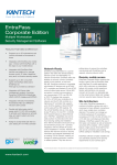
6.1.1 PG4929/PG8929/PG9929
6
7
5
1
2
3
4
1.
2.
3.
4.
5.
6.
7.
Away arm
Stay arm
Disarm
Panic
Command Output 1
Message LED
Status LEDs
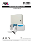
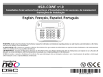
6.1.2 PG4939/PG8939/PG9939
1
6
5
2
1.
2.
3.
4.
5.
6.
3
4
Away Arm
Stay Arm
Disarm
Panic
Command Output 1
LED
6.2 Using Proximity Tags
The MPT proximity tag is ideal for people who have difficulties remembering codes or who do not interact with the system regularly. To operate properly, Proximity tags must be enrolled in the system. The LED Bar flashes 3 times upon a valid Prox Tag
being read by the keypad successfully. If the Proximity Tag is invalid, the LED Bar will stay ON and an error tone will sound.
For more information see: "Enrolling and Deleting Proximity Tags".
6.3 SMS Command and Control
SMS Command and Control allows you to send text messages to your system, enabling the system to perform certain actions. For a
list of commands and how to send them see the following table. As a security measure, only phone numbers configured by your
installer will be permitted to contact your system. Messages from all other phone numbers will be rejected.
Note: This is a supplementary feature that has not been investigated by UL/ULC. Must be enabled and configured by installer.
Only supported with an LCD keypad.
6.3.1 Using the Keypad to Lookup the Number to Call for SMS Commands
The phone number of the system is programmed by the installer. To quickly find the phone number perform the following steps.
To find the System’s Phone Number
LCD Display
1.
Check that the Ready indicator
is on and the system is disarmed.
- 19 -
Date Time
JAN 02/13 2:06a
Chapter 6
2.
Press [*][6]
Press (*) for <>
User Functions
OR
press [*]and use the scroll keys to navigate to User Functions press [*] and enter
[Master Code].
3.
Press [1][1] or use the scroll keys to navigate to SMS Programming and press [*].
Press (*) for <>
SMS Programming
4.
Scroll to navigate to SMS Programming and press [*]. The phone number to send your
SMS commands to displays.
Press (*) for <>
GSM Phone No.
6.3.2 Sending SMS Commands to your System
In order to successfully send commands to your system from your cellphone, you must send SMS messages in the proper format. If
configured, commands require the inclusion of a User Access Code in your message. The access code will be verified by the system before executing any commands.
Additional information about sending SMS commands:
l
Text messages are not case sensitive and extra spaces are ignored.
l
In multi-partition systems and if the User has rights to manage the desired partitions, commands can be sent to specific
partitions by including the partition number. For more information on partitions see: "Managing Partitions".
l
If the panel is configured to require an Access Code and the code is not sent or is invalid, the panel will send a notification to the user advising the command was unsuccessful.
The following table lists all available SMS commands with examples of how to enter the Partition number and access codes. The
format for entering commands is as follows:
Command Partition number Access Code
Stay Arm
001
1234
Note: Verify with your installer that the Partition number and access code are required in your SMS message. If one or both are
not required, do not enter them in your SMS message.
Note: Responses to Status and Alarm Memory requests may require more than 1 SMS message, depending on status of the system.
There is a 10 second delay between transmission of SMS messages.
6.3.3 SMS Commands
Commands
Notes
Stay Arm
Stay arms the system
Away Arm
Away arms the system
Night Arm
Night arms the system
Disarm
Disarms the system
Activate Command Output 1
Activates Output 1
Activate Command Output 2
Activates Output 2
Activate Command Output 3
Activates Output 3
Activate Command Output 4
Activates Output 4
Deactivate Command Output 1
Deactivates Output 1
Deactivate Command Output 2
Deactivates Output 2
Deactivate Command Output 3
Deactivates Output 3
Deactivate Command Output 4
Deactivates Output 4
Bypass 001
Bypasses specified zone number
Unbypass 001
Clears the bypass from the specified zone number
Status Request
Omitting the partition number causes the system to send a status report
for all partitions. To request a status report for a specific partition enter
the appropriate partition number.
Alarm Memory Request
Omitting the partition number causes the system to send a status report
for all partitions. To request a status report for a specific partition enter
the appropriate partition number.
Help
The Help command generates an SMS response listing all Interactive
commands that can be sent to the module. Access Code is not required.
- 20 -
Chapter 6
6.3.4 SMS Responses from your System
SMS responses are sent to the phone that initiated the command.
System Response
Notes
Successful
Sent when a command and control function is successfully performed by the panel.
Unsuccessful
Sent when a command and control function not successfully performed by the panel.
Invalid Command
Sent when a command sent was not accepted as valid by the system.
System Stay Armed
Sent in response to a status request and if a partition is stay armed.
System Away Armed
Sent in response to a status request and if a partition is away armed.
System Night Armed
Sent in response to a status request and if a partition is night armed.
System Disarmed Ready
Sent in response to a status request and if a partition is disarmed and ready to arm.
System Disarmed Not Ready Sent in response to a status request and if a partition is disarmed and is not ready to arm.
System is in Alarm
Sent in response to a status request and if a partition is in alarm.
Service is Required
Sent in response to a status request and if a partition is in trouble.
No Alarm Memory
Sent in response to a alarm memory request and there are no alarms in memory.
- 21 -
Chapter 7
7.0 Managing Users
Up to 95 different user access codes can be programmed in the PowerSeries Neo. Each user access code can be:
l
Uniquely labeled.
l
Assigned a proximity tag. In order to operate, proximity tags must be enrolled in the system.
l
Assigned to only operate specific partitions. For more information on partitions see: "Managing Partitions".
l
Configured with additional attributes. For more information see: "Configuring additional User Options".
Note: Your installer configures all access codes to be either 4 or 6 digits. You cannot have access codes of both lengths on your
system.
Programed zones are indicated on the LCD screen. For more information on user flags see the following table. On an ICN or LED
keypad programmed users will have their digits displayed
User Indications
LCD Display Indications Description
User Code 01 - -
Unprogrammed code
User Code 01 P P
Programmed code
User Code 01 T T
Code and tag/key are programmed
7.1 Access Code Types
The alarm system provides the following user access code types:
Code
Add User
Delete User
Arm Disarm
Access Codes
User Functions
Installer
Master
All
All
Yes
Yes
Yes
Yes
No
User
No
No
Yes
Yes
No
No
No
Supervisor
All but Master
All but Master
Yes
Yes
Yes
Yes
No
Duress
No
No
Yes
Yes
No
No
No
One-time user
No
No
Yes 1/day
No
No
No
Installer and Master code are system codes that can be changed but not deleted. The other codes are user-defined and can be added
or deleted as necessary. By default, access codes have the same partition and attribute programming as the code used to program
them.
Note: When using 6-digit access codes, the minimum number of access code variations is 10526 per user. Additionally, there are
no disallowed codes.
Master
Code
By default the master code can access all partitions and can perform any keypad function. This code can be used
to program all access codes, including the supervisor and duress codes. The master code is code # [01].
User
Codes
This type of access code is used to arm and disarm assigned partitions and can access the User Functions menu.
Supervisor Use when you want to allow additional users to manage Access Codes [*5] or User Functions [*6]. Supervisor
codes created by the master code will have the same attributes as the master code. Supervisor codes created by
Codes
another supervisor code will have the same attributes, except the supervisor attribute. Must be assigned manually
afterward. After creation, attributes can be changed for all supervisor codes. For information on how to program a
supervisor code see "Configuring additional User Options".
Duress
Codes
Use if forced to access your keypad under threat. Duress codes function the same as user access codes, except
they transmit a Duress Report to your monitoring station when used to perform any function on the system.
Duress codes cannot be used to access Access Codes [*5], User Functions[*6] or Installer [*8] menus. For information on how to program a Duress Code see "Configuring additional User Options".
One Time Use when needing to grant someone one time access to your home once per day, i.e., a cleaning person or conUser Code tractor. The ability to disarm the system is reset at midnight or when the one time user code is keyed in by the master code user. For information on how to program a One Time User Code see "Configuring Additional User
Options".
- 22 -
Chapter 7
To Open the Access Codes Menu
1.
LCD Display
Press [*][5]
Press (*) for <>
Access Codes
OR
press [*] and use the scroll keys to navigate to Access Codes and press [*].
2.
Enter [Master or supervisor code].
Present Tag or
Enter Code
3.
Enter [2 digit user #]
Press (*) for <>
{User Label}
OR
scroll through the list of users and press [*]. On an LED keypad the user number
will begin flashing.
4.
To go back to the Ready state press [#].
7.1.1 Adding, Changing and Deleting Access Codes
Each configured user is assigned a number from 01-95. Access codes cannot be duplicated.
To Add or Change User Access Codes
LCD Display
1.
From the desired user press [*] or [1].
Press (*) for <>
Access Code
2.
Enter a new 4 or 6 digit access code. After entering a new code you will be automatically returned to the previous menu, and on an LCD display the flag is changed
to P from -. On an ICN or LED keypad the programmed user will have their digits
displayed. If a duplicate code is entered the error tone will sound. After the code is
programmed, the keypad returns to the previous LCD display.
Enter New Code
AAAA
To Delete a User Access Code
1.
LCD Display
From the desired user press [*] or [1].
Press (*) for <>
Access Code
2.
Press [*]. The code is deleted, and you are returned to the previous screen. The flag
is changed to - from P. On an ICN or LED keypad the programmed user’s digits will
cease being displayed. After the code is programmed, the keypad returns to the previous LCD display.
Note: Any proximity tags associated with deleted user codes will need to be re-enrolled.
Enter New Code
030516
7.1.2 Enrolling and Deleting Proximity Tags
When enrolling or deleting proximity tags for a user, the system provides a choice of option depending on if tag is already enrolled
or not. For more information on see: "Using Proximity Tags".
To Enroll a Proximity Tag
LCD Display
1.
From the desired user press [2] or scroll to Prox Tag and press [*].
Press (*) for <>
Prox Tag
2.
If no tag is enrolled for this user you will be asked to present the tag to the
reader.
Present Tag or
Press # to Exit
l
If the card successfully enrolls the blue LED bar flashes.
Tag Enrolled
Successfully
l
If the tag is invalid the following message is displayed.
Invalid Tag
Not Enrolled
If the tag already is enrolled with another user the following message is displayed.
Duplicate Tag
Not Enrolled
l
To Delete a Proximity Tag
LCD Display
1.
From the desired user press or scroll to Prox Tag and press [*].
Press (*) for <>
Prox Tag
2.
If a tag is enrolled for this user you will be asked if you would like to delete the Tag.
Press [*] to delete the tag.
* To Delete Tag
Press # to Exit
Tag Deleted
Successfully
- 23 -
Chapter 7
7.1.3 Naming a User
Adding or editing labels are accomplished by using the keypad to input the desired letters or numbers. The following figure depicts
the three letters and one number that corresponds to each keypad button.The first press of the number key displays the first letter.
The second press displays the second letter, etc.
[1]
[2]
[3]
A, B, C, 1 D, E, F, 2 G, H, I, 3
[4]
[5]
[6]
J, K, L, 4 M, N, O, 5 P, Q, R, 6
[7]
[8]
[9]
S, T, U, 7 V, W, X, 8 Y, Z, 9,0
[0]
Space
Entering letters using the keypad
To Edit a User Label
LCD Display
1.
From the User Codes menu press [3] or scroll to User Labels and press [*].
2.
Use the arrow keys to move the cursor to a blank space or existing character.
3.
Press the number key corresponding to the appropriate letter as shown in the previous figure.
4.
When the required letter or number is displayed use the arrow keys to scroll to the
next letter.
5.
When finished, press the [*] key, use the keys to scroll to Save then press [*].
Press (*) for <>
User Labels
Program Name
{User 1 Label}
7.1.4 Assigning a Partition to a User code
User codes can be configured to have access only to specific partitions. For more information see: "Managing Partitions".
Note: Partitions are configured by your installer.
To Assign a Partition to a User code
LCD Display
1.
From the desired user press [4] or scroll to Partition Assign and press [*].
Press (*) for <>
Partition Assign
2.
Press [*] to change the partition assignment for the user code, Y or N.
(*) To Toggle <>
{Partition Lb} Y
If using an LED or ICN keypad press the corresponding number key for the partition,
1 to 8, to change the programming of the option..
7.2 Configuring additional User Options
Users can also be assigned the following options:
[1] Supervisor Code For more information see: "Access Code Types".
[2] Duress Code
For more information see: "Access Code Types".
[3] Zone Bypass
Grants the user the ability to bypass zones.
[4] Remote Access
Grants the user the ability to use SMS features. For more information see: "SMS Command and Control"
[7] Bell Squawk
Use to generate a bell squawk when arming/disarming the system.
Note: When using wireless keys to arm/disarm the system there will be:
l
one bell squawk for arming
l
two bell squawks for disarming.
l
three squawk pairs when disarming with an alarm in memory.
[8] One Time Use
For more information see: "Access Code Types".
To Configure additional User Options
LCD Display
1.
From the desired user press or scroll to User Options and press [*].
Press (*) for <>
User Options
2.
Use the keys to cycle through the User Options and press to toggle configuring the displayed option.
(*) To Toggle <>
Bell Squawk Y
OR
If using an LED or ICN keypad press the [feature number as listed above].
- 24 -
Chapter 8
8.0 User Functions
The PowerSeries Neo allows for a variety of user configurable functions as listed below:
Event Buffer
Auto Arm Time
Time and Date
System Service/DLS Late To Open Time Buzzer Control
Auto Arm/Disarm User Call-up
Late To Open
Contrast Control Voice Chime
Brightness Control Voice Prompt
User's Walk Test
Note: User Functions can only be modified when the system is disarmed.
To access the User Function menu
1.
LCD Display
Press [*][6]
Press (*) for <>
User Functions
OR
press [*] and use the scroll keys to navigate to User Functions and press [*].
2.
Enter Master code and scroll through the options listed above.
Present Tag or
Enter Code
then
Select Option <>
Event Buffers
3.
To go back to the Ready state press [*].
8.1 Event Buffer
The Event Buffer displays a list of the last 1000 events on your system. You may only view the event buffer using an LCD keypad.
To view the Event Buffer
LCD Display
1.
From the User Function menu
scroll to Event Buffer and press [*].
2.
Press
to scroll through the Event Buffer. When finished press [*] to return
to the Ready state.
Select Option <>
Event Buffer
000X-Message
Time/Date
8.2 Setting the Time and Date
To set the Time and Date
LCD Display
1.
From the User Function menu use the shortcut key [0][1] or press
to Time and Date and press [*].
to scroll
2.
Use the number keys to set the time and date. When finished press [*] to return to the
Ready state.
Select Option <>
Time and Date
HH:MM MM/DD/YY
11:12 01/14/13
8.3 Enabling/Disabling the Auto Arm/Disarm Feature
Note: Access to this feature must be configured by installer.
To enable/disable Auto Arm/Disarm
LCD Display
1.
From the User Function menu use the shortcut key [0][2] or press
to Auto Arm/Disarm.
2.
Press [*] to enable/disable the Auto Arm/Disarm feature.
to scroll
Press (*) for <>
Auto Arm/Disarm
Auto Arm/Disarm
is Enabled
or
Auto Arm/Disarm
is Disabled
3.
When finished press [*] to return to the Ready state.
8.4 Setting the Auto Arm Time
The system can be configured to Auto arm at a specific time on each day of the week. If a specific time is not configured for a
day of the week the system will not arm automatically on that day.
Note: Access to this feature must be configured by installer.
To set the Auto Arm Time
LCD Display
1.
From the User Function menu use the shortcut key [0][3] or press
to Auto Arm Time.
- 25 -
to scroll
Press (*) for <>
Auto Arm Time
Chapter 8
2.
Press [*]to open a days of the week sub menu. Scroll the days of the week and press
[*] to set the time for that day.
Press (*) for <>
Sunday
OR
If using an ICN or LED keypad to select the desired day press [1-7] where 1=
Sunday and 7=Saturday.
3.
Using a 24 hour format, set the desired time. After you enter the fourth digit the
screen will revert back to the previous day of the week menu. Entering the time 9999
disables the late to open feature for that day. When using an ICN or LED keypad the
time will not display.
Set 24Hr Time
Enter HH:MM 9999
4.
Continue setting the time for the desired days of the week. When finished press [#] to
return to the Ready state.
Set 24Hr Time
Enter HH:MM 9999
Note: If you set an invalid time the error tone will sound.
8.5 Allowing the Installer to Service your System Remotely - DLS
Occasionally, your installer may need to remotely access the Installer programming of your security system using Downloading
Software (DLS). In order for this to successfully occur, you may need to manually allow access to your system.
Note: Access to this feature must be configured by installer.
To enable/disable the System Service/DLS
LCD Display
1.
From the User Function menu use the shortcut key [05] or press to scroll to SystemServ/DLS.
Press (*) for <>
SystemServ/DLS
2.
Press [*] to enable/disable the SystemServ/DLS feature.
SystemServ/DLS
is Enabled
3.
When finished press [#] to return to the Ready state.
or
SystemServ/DLS
is Disabled
8.6 User Callup
Using DLS, User Call-up allows your system to make one attempt to connect to the installer’s remote computer. For a successful
connection, the remote computer must be waiting for the system’s call.
Note: Access to this feature must be configured by installer.
To perform a User Callup
LCD Display
1.
From the User Function menu use the shortcut key [0][6] or press
to User Callup.
2.
When finished press [*] to return to the Ready state.
to scroll
Press (*) for <>
User Callup
8.7 Late to Open
Typically used to track children after school, the Late to Open feature allows you to be notified if your alarm system is not disarmed by a programmed time of day.
For example, if you arrive from work at 5pm, and your child arrives home at 4 p.m. you could set the programmable time for 4:15
p.m. If the system is not disarmed by 4:15 an alert would be sent to the monitoring station and an event will be stored in the event
buffer viewable from an LCD keypad. If SMS notifications are configured for your system the monitoring station will notify you
via SMS message. For more information see: "Event Buffer".
Note: Access to this feature must be configured by installer.
To enable/disable Late to Open
LCD Display
1.
From the User Function menu use the shortcut key [0][9] or press
to Late to Open.
2.
Press [*] to enable/disable the Late to Open feature.
3.
When finished press [*] to return to the Ready state.
to scroll
Press (*) for <>
Late to Open
Late to Open
is Enabled
or
Late to Open
is Disabled
To set the Late to Open time
1.
LCD Display
From the User Function menu use the shortcut key [1][0] or press
to Late to Opn Time.
- 26 -
to scroll
Press (*) for <>
Late to Opn Time
Chapter 8
2.
Press [*] to open a days of the week sub menu. Scroll the days of the week and press
[*] to set the time for that day.
Press (*) for <>
Sunday
OR
If using an ICN or LED keypad to select the desired day press [1-7] where 1=
Sunday and 7=Saturday.
3.
Using a 24 hour format, set the desired time. After you enter the fourth digit the
screen will revert back to the previous day of the week menu. Entering the time 9999
disables the late to open feature for that day. When using an ICN or LED keypad the
time will not display.
Set 24Hr Time
Enter HH:MM 9999
4.
Continue setting the time for the desired days of the week. When finished press [#] to
return to the Ready state.
Note: If you enter an invalid time the error tone will sound.
8.8 Changing the Brightness of the LCD keypad
To change the LCD brightness
LCD Display
1.
From the User Function menu use the shortcut key [1][2] or press
to Bright Control and press [*].
to scroll
2.
Enter the 2 digit value or scroll to the desired brightness level and press [*] to return
to the previous menu.
3.
Press [#] to return to the Ready state.
Press (*) for <>
Bright Control
Brightness <>
Level... XX
8.9 Changing the Contrast of the LCD keypad
To change the LCD contrast
LCD Display
1.
From the User Function menu use the shortcut key [1][3] or press
to Contrast Control and press [*].
to scroll
2.
Enter the 2 digit value or scroll to the desired contrast level and press [#] to return to
the previous menu.
3.
Press [#] to return to the Ready state.
Press (*) for <>
Contrast Control
Contrast <>
Level... XX
8.10 Setting the Buzzer volume
To change Buzzer volume
LCD Display
1.
From the User Function menu use the shortcut key [1][4] or press
to Contrast Control and press [*].
to scroll
2.
Enter the 2 digit value or scroll to the desired volume level and press [#] to return to
the previous menu.
3.
Press [#]to return to the Ready state.
Press (*) for <>
Buzzer Control
Buzzer <>
Level... XX
8.11 Setting the Voice Prompt volume
This feature is only available when using an HS2LCDWFPV wireless keypad.
To change Voice Prompt volume
LCD Display
1.
From the User Function menu use the shortcut key [1][5] or press
to Voice Prompt and press [*].
to scroll
2.
Enter the 2 digit value or scroll to the desired volume level and press to return to the
previous menu.
3.
Press [#] to return to the Ready state.
Press (*) for <>
Voice Prompt
Voice Prompt <>
Level... XX
8.12 Setting the Voice Chime volume
This feature is only available when using an HS2LCDWFPV wireless keypad.
To change Voice Chime volume
LCD Display
1.
From the User Function menu use the shortcut key [1][6]or press
Voice Chime and press [*].
2.
Enter the 2 digit value or scroll to the desired volume level and press [#] to return to
the previous menu.
- 27 -
to scroll to
Press (*) for <>
Voice Chime
Voice Chime <>
Level... XX
Chapter 8
3.
Press [#] to return to the Ready state.
8.13 Resetting the System
8.13.1 Engineer's Reset
If an alarm has occurred on your system, the system will not allow you to rearm (Ready light is OFF). You will need to contact
your installer. They will check and reset the system for you. This may involve a visit to check your system. After the reset is performed, your system will function properly again.
8.13.2 Remote (Anti-code) Reset
When configured by the installer, an alarm condition will cause the system to require a remote reset and arming will no longer be
possible after the system is disarmed. This feature ensures that the end user contacts the monitoring station following an alarm condition. The system keypads will display that a remote reset is required and will show a random 4 digit remote reset code. The user
must contact their monitoring station and provide the code that's displayed on the keypad. The monitoring station operator will
provide a different 4 digit code that the user can enter at the system keypad which will clear the remote reset condition, allowing
the panel to be armed again.
Some user functions are still available while the system is locked out. The user can loan the keypad to a different partition, and can
access [*][6] User Functions so the event buffer can be reviewed to determine cause of the alarm condition. The [*][3] Alarms in
Memory and [*][7] command output menus are also available during the remote reset condition.
This feature is intended to be used with burglary zones. Fire alarms do not generate remote reset.
Each partition will generate a unique Remote Reset code on the system keypads and must be unlocked separately.
8.14 User's Walk Test
8.14.1 Full System Walk Test
Allows the user to verify the operation of system detectors and notifies the central station that a Walk Test is in progress and must
be configured by installer.
IMPORTANT: During a system (walk) test, do not activate any:
l
Fire, Auxiliary or Police buttons
l
Fire or CO sensors
A full system test is comprised of activating each sensor in turn. Open each door, window and walk-in areas with motion detectors.
It is recommended you perform system tests during off-peak hours, such as early morning or late evening.
To Initiate a Walk Test
LCD Display
1.
From the ready state press [*][6] and enter the [Master Code] to access User Functions.
Press (*) for <>
User Functions
2.
Press [08] or use the scroll keys
to navigate to Walk Test and press [*].
The system activates all keypad sounders and bell/sirens for two seconds and also notifies the central Station that a walk test has begun.
Press (*) for <>
Walk Test
3.
Trigger each detector (zone) in sequence. A squawk occurs at the keypad, all LEDs
on the keypad will flash and the violation will be recorded in the Event Buffer.
4.
Restore zones. Press [*][6][Master Code][8] to end the Walk Test. The system will
notify the Central Station that the walk test has been terminated.
Note: Fire zones, the 'F' key, and 2-wire smoke detectors are excluded from this test. Violation of these zones will cause the system to exit the walk test then generate and transmit an alarm condition to the central station.
If a zone is not violated within 15 minutes of activating the Walk Test, the system will automatically exit the Walk Test and
resume normal operation.
Note: This feature is not available in CP-01 panels.
To Initiate/Cancel a Walk Test
LCD Display
1.
From the User Function menu, use the shortcut key [08] or press
to Walk Test.
2.
Press [*] to enable/disable the Walk Test feature.
3.
Or, when finished press [*] to return to the Ready state.
to scroll
Press (*) for <>
Walk Test
Walk Test
is Enabled
Walk Test
is Disabled
- 28 -
Chapter 8
8.15 Trouble Conditions
Trouble Conditions (Level 1) are comprised of various trouble types (Level 2) which may in turn be related to a specific zone,
module, device or additional type of system equipment (Level 3). For an explanation of possible trouble conditions and the recommended actions required.
When the system detects a trouble condition the following occurs:
l
The Trouble indicator turns on.
l
The keypad beeps once every 10 seconds.
l
Press the [*] key to silence the keypad beeps.
Examining troubles is done by pressing [*][2]. When viewing troubles, the trouble indicator flashes to identify the level of trouble
being viewed. One flash = level 1, two flashes = level 2 etc.
Arming of your system may be impeded by a trouble. To override this condition, enter [*2] and scroll to acknowledge all troubles
and press [*] or enter 999.
Trouble
Condition
Trouble
Description
#
Level 1
Trouble
Types
Trouble Trouble
#
Notification
Level 2 Level 3
Note: Trouble #s are used to identify the number to view the trouble and depending on the keypad type being used, identifies
which LED or digit illuminates to display the trouble. Similarly, Trouble Notification identifies the range that may be displayed
on the keypad. When exploring the trouble levels, the Trouble indicator will flash to identify which level you are currently viewing.
Service
Required
01
Battery Trouble 02
Bus Voltage
03
Assorted Trouble types.
Time and Date troubles can be resolved by resetting the
Time/Date. To set Time/Date press [*][6][0][1]. For all
other troubles call for service.
The system has detected a battery trouble condition. Call
for service.
Bell Circuit
01
RF Jam
02
Auxiliary Sup- 03
ply
Loss of clock 04
Output 1 Fault 05
Low Battery
(System
Label)
01
n/a
No Battery
service (System Label)
02
High Current
Output Low
Battery
04
Module 1-4
High Current 05
Output No Battery
Module 1-4
Power Supply 07
Low Battery
Module 1-4
Power Supply 08
No Battery
Power supply
1-4
A module has detected a low voltage on its corbus red ter- HSM2HOST
minal.
Keypad
Zone
Expander
n/a
01
n/a
02
Keypad 1-16
04
Zone
expander 115
Power Supply 05
Power supply
1-4
High Current
Output
06
Output terminal 1-4
Output
Expander
08
Output module 1-16
HSM2955 Bus 09
Voltage
(Audio
Expander)
- 29 -
n/a
Chapter 8
Trouble
Condition
Trouble
Description
#
Level 1
AC Troubles
04
Trouble
Types
The system is experiencing loss of power. Call for service. Zone
If the building and/or neighborhood has lost electrical
power, the system will continue to operate on battery for
Siren
several hours.
Repeater
Trouble Trouble
#
Notification
Level 2 Level 3
01
Zone label or
001-128
03
Siren 1-16
04
Repeater 1-8
Power Supply 05
Power supply
1-4
High Current
Output
Output terminal 1-4
06
System Label 07
Device Faults
05
Device Battery 06
Device
Tampers
07
RF Delinquency 08
The system has detected an issue with one or more connected devices. Call for service.
Gas
Heat
CO
Freeze
Probe Disconnected
Fire
Zone
01
Zone label or
001-128
Keypad
02
Keypad 1-16
Siren
03
Siren 1-16
Repeater
04
Repeater 1-8
01
Zone label or
001-128
02
Keypad 1-16
03
Siren 1-16
Repeater
04
Repeater 1-8
User
05
Wireless key
1-32
Zone
01
Zone label or
001-128
Keypad
02
Keypad 1-16
Siren
03
Siren 1-16
Repeater
The system has detected an issue with one or more of the Zone
device batteries. For Zone, Keypad and Wireless Key battery troubles see the accompanying documentation for how Keypad
to change the batteries.
Siren
The system has detected a tamper condition with one or
more devices on the system. Call for service.
The system has detected wireless signal interference that
is causing improper system operation. Call for service.
- 30 -
n/a
04
Repeater 1-8
Audio Station 05
Audio Station
1-4
Zones
01
Zone label or
001-128
Keypad
02
Keypad 1-16
Siren
03
Siren 1-16
Repeater
04
Repeater 1-8
Chapter 8
Trouble
Condition
Module Supervision
Module
Tampers
Trouble
Description
#
Level 1
Trouble
Types
Trouble Trouble
#
Notification
Level 2 Level 3
09
HSM2HOST
01
n/a
Keypad
02
Keypad 1-16
Zone
Expander
04
Zone
Expander 115
10
Communications 11
The system has detected a supervisory trouble condition
with one or more modules on the system. Call for service.
The system has detected a tamper condition with one or
more modules on the system. Call for service.
Power Supply 05
Power supply
1-4
High Current
Output
06
Output terminal 1-4
Output
Expander
08
Output module 1-16
Audio
Expander
09
n/a
HSM2HOST
01
n/a
Keypad
02
Keypad 1-16
Zone
Expander
04
Zone
Expander 115
Power Supply 05
Power supply
1-4
High Current
Output
06
Output terminal 1-4
Output
Expander
08
Output module 1-16
Audio
Expander
09
n/a
Alt. Comm
10
n/a
The system has detected a communication trouble. Call for TLM Trouble 01
service.
FTC Trouble 02
n/a
SIM Lock
03
n/a
Cellular
04
n/a
Ethernet
05
n/a
Receiver
06
Receiver 1-4
Supervision
Receiver
07
Receiver 1-4
Alt Comm
Fault
09
n/a
Alternate
10
Communicator
FTC
Not Networked 12
The system has detected a network trouble condition with Zone
one or more modules on the system. If the trouble does not
restore within 20 minutes, call for service.
Keypad
- 31 -
Receiver 1-4
Receiver 1-4
01
Zone label
001-128
02
Keypad 1-16
Siren
03
Siren 1-16
Repeater
04
Repeater 1-8
User
05
Users 01-95
Chapter 9
9.0 Managing Partitions
A partition is a limited area of the premises which operates independently from the other areas. Partitioning a system can be beneficial if the property has outbuildings that need to be secured independently of a main area or if the home has a separate apartment.
Each partition can have its own keypad, or a keypad can have access to all partitions. User access to partitions is controlled via
access code. A master code can access the entire system and partitions, while a user code is limited to assigned partitions.
9.1 Partitions
Keypads can be configured to control an individual partition or all partitions.
Note: Access to this feature must be configured by installer.
9.1.1 Single Partition Operation
Single partition keypads provide access to alarm functionality for an assigned partition.
Single partition keypads behave as follows:
l
Displays the armed state of the partition.
l
Displays open zones, if assigned to the partition the keypad is on.
l
Displays bypassed zones and allows zone bypassing or creating bypass groups of zones assigned to the keypad partition.
l
Displays system troubles (system low battery, system component faults/tampers).
l
Displays alarms in memory that occurred on the partition.
l
Allows the door chime to be Enabled/disabled.
l
System test (sounds bells/PGMs assigned to the partition).
l
Label programming (zone, partition and user labels for the partition).
l
Command output controls (outputs assigned to the partition, or global outputs such as smoke detector reset).
l
Temperatures.
9.1.2 Loaning a Keypad to Another Partition
Keypads can be loaned to operate on other partitions (LCD keypads only). When a keypad is loaned from either the global state or
from another partition, it may be configured to behave on the loaned partition just as it would if it was originally assigned there.
Loaning a keypad to another partition does not require an access code; However, no function that requires an access code can be
performed on that partition unless the user’s code has sufficient permissions. The status of each partition will be identified by a partition flag. For an explanation on partition flags, see the following table.
To Loan a Keypad to Another Partition
LCD Display
1.
Press and hold the [#] key for 2 seconds.
2.
Select a partition by pressing digits 1 to 8. The keypad is temporarily loaned to
another partition. If the keypad is inactive for more than 30 seconds, it reverts to its
original partition.
1 2 3 4 5 6 7 8
R R - - - - - N
Partition Flags
LCD Display
Flag
Description
1 2 3 4 5 6 7 8
R X A ! E - - N
1-8
Partition number
R
Partition is ready to be armed
X
Partition is in exit delay
N
Partition is not ready to be armed
!
Partition is in alarm
E
Partition is in entry delay
-
Partition is not configured
A
Partition is armed
9.2 Fire and CO Zone Types
l
l
l
l
If a Fire zone generates an alarm only the partition the fire zone is assigned to will go into alarm. Other partitions retain
their current state.
If the [F] key on a global keypad is used to generate an alarm all enabled partitions will go into alarm.
One or more fire keypads may be located on any partition.
On alarm, the fire auto-scroll display appears on all partition keypads and on all global keypads. Fire alarm silence and
fire system reset may be done directly on any partition keypad. To silence a fire or CO alarm from a global keypad
requires that the global keypad be loaned to one of the partitions.
- 32 -
Chapter 10
10.0 Additional Features
10.1 Turning the Chime ON/OFF
Turning the chime on audibly notifies you whenever an entry/exit sensor is tripped.
To turn the Chime ON or OFF
l
Press to toggle the Chime ON or OFF for the current partition. An access code
may be required to change this setting.
LCD Display
Door Chime
Feature ON
Door Chime
Feature OFF
10.2 Audio Verification
Allows the monitoring station to initiate a 2-way audio (talk/listen) or 1-way audio (listen-in only) session when an alarm has been
received. This feature is used to verify the nature of the alarm or determine the type of assistance required by the occupant.
Note: This is a supplementary feature that has not been investigated by UL/ULC.
Note: Must be enabled and configured by installer.
10.3 Visual Verification
Allows the monitoring station to use video clips captured from system motion cameras for verification of any alarms.
Note: This is a supplementary feature that has not been investigated by UL/ULC.
Note: Must be enabled and configured by installer.
10.3.1 System Lockout due to Invalid Attempts
If too many invalid access codes are entered, your system can be configured to automatically lock out inputs from all keypads, wireless and proximity keys, and SMS commands for a specified duration. When any keys are pressed, an error tone will sound. FMP
keys are still active during Keypad Lockout.
Note: Feature and lockout duration must be configured by installer.
10.4 Command Outputs
While being useful for many applications, Command outputs are typically configured to operate items such as garage doors or electric gates. Additionally, Command outputs can be assigned to follow a schedule configured by your installer.
This is a supplementary feature that has not been investigated by UL/ULC.
Must be configured by installer.
To Activate a Command Output
LCD Display
1.
Press [*][7] and if required enter your [access code].
Output Control <>
Scroll to View
OR
press [*] and use the scroll keys to navigate to Output Control.
2.
Press the number configured to the command output
Output
Activated
OR
use the scroll keys to navigate to the desired command output and press [*].
To configure a Command Output to Follow a Schedule
1.
2.
LCD Display
Press [*][7]and use the scroll keys to navigate to Follow Schedule and press [*], followed by your access code.
Output Control <>
Scroll to View
OR
press [*][7][9][User Code].
then
Press (*) to
Follow Schedule
Press the command output #(1-4) to toggle scheduling and if required enter your
[access code]
Partition 1 <>
Command O/P 1 Y
OR
use the scroll keys to navigate to the desired command output and press to toggle
scheduling and if required enter your [access code].
10.5 Burglary Verification
The Control Panel includes cross zone and sequential detection features that require a trip on two or more zones within a given
time period, to generate a confirmed alarm and immediate police response.
Note: Must be enabled and configured by installer.
- 33 -
Chapter 10
10.6 Swinger Shutdown
The Control Panel has a swinger shutdown feature that when enabled a programmable number of trips shall shut down the zone.
All burglary zone types have this feature enabled in CP-01 installations.
Note: Must be enabled and configured by installer.
10.7 Call Waiting
The Control Panel includes a programmable option for call waiting to prevent a call waiting line from interfering with the alarm
verification process. This option is disabled by default.
Note: Must be enabled and configured by installer.
10.8 Fire Alarm Verification
Fire Alarm Verification is an available option for Fire zones. If configured, once the conditions for alarm verification are met the
fire alarm will sound and an alarm transmission will be sent to the monitoring station.
Note: Must be enabled and configured by installer.
- 34 -
Chapter 11
11.0 Regulatory Agency Statements
11.1 CE Compliance Statement
This Product is in Conformity with EMC Directive 2004/108/EC based on results using harmonized standards in accordance with
article 10(5), R&TTE Directive 1999/5/EC based on Following Annex III of the directive and LVD directive 2006/95/EC based on
results using Harmonized standards.
11.2 EN50131 Compliance Statement
This product meets the requirements of Class II, Grade 2 equipment as per EN50131-1: 2006+A1:2009, EN50131-3:2009,
EN50131-6:2008 (Type A), EN50136-1-1:1997, EN50136-2-1, EN50136-2-3 (ATS2) Standards. This device is suitable for use in
systems with the following notification options.
-A (use of two warning devices and internal dialer required
-B (self-powered warning device and internal dialer required
-C (use of DSC compatible alternate communicator in back-up or redundant mode)
-D (use of DSC compatible alternate communicator with encryption enabled required.)
Note: For EN50131 complian installations only the intrusion portion of the alarm system has been investigated. Fire Alarm and Auxiliary (Medical) Alarm functions were not included in the evaluation of this product under the requirements of the above mentioned
standards.
The model HS2128, HS2064, HS2032, HS2016 Control Panel has been certified by Telefication according to EN50131-1:2006
+A1:2009, EN50131-3:2009, EN50131-6:2008 (Type A) and EN50136-1:1997 (ATS2) for Grade 2, Class II.
11.3 UK Compliance Statement
In the UK this product is suitable for use in systems installed to conform to PD 6662:2010 at Grade 2 and environmental class 2
with the following notification options: A, B, C, D, X
+HUHE\ '6& GHFODUHV WKDW WKLV GHYLFH LV LQ FRPSOLDQFH ZLWK WKH HVVHQWLDO
UHTXLUHPHQWVDQGRWKHUUHOHYDQWSURYLVLRQVRI'LUHFWLYH(&
7KH FRPSOHWH 577( 'HFODUDWLRQ RI &RQIRUPLW\ FDQ EH IRXQG DW
KWWSZZZGVFFRPOLVWLQJVBLQGH[DVS[
&=( '6& MDNR Y¿UREFH SURKODģXMH ŀH WHQWR Y¿UREHN MH Y VRXODGX VH YģHPL
UHOHYDQWQ¯PLSRŀDGDYN\VPÝUQLFH(&
'$1'6&HUNO¨UHUKHUYHGDWGHQQHNRPSRQHQWHQRYHUKROGHUDOOHYLNWLJHNUDYVDPW
DQGUHEHVWHPPHOVHUJLWWLGLUHNWLY(&
'87 +LHUELM YHUNODDUW '6& GDW GLW WRHVWHO LQ RYHUHHQVWHPPLQJ LV PHW GH HLVHQ HQ
EHSDOLQJHQYDQULFKWOLMQ(&
),1'6&YDNXXWWDDODLWWHHQW¦\WW¦Y¦QGLUHNWLLYLQ(&ROHQQDLVHWYDDWLPXNVHW
)5( 3DU OD SU«VHQWH '6& G«FODUH TXH FH GLVSRVLWLI HVW FRQIRUPH DX[ H[LJHQFHV
HVVHQWLHOOHVHWDXWUHVVWLSXODWLRQVSHUWLQHQWHVGHOD'LUHFWLYH(&
*(5+LHUGXUFKHUNO¦UW'6&GD¡GLHVHV*HU¦WGHQHUIRUGHUOLFKHQ%HGLQJXQJHQXQG
9RUUDXVHW]XQJHQGHU5LFKWOLQLH(&HQWVSULFKW
*5(˂˜˞˱ˬ˲˭˞ˮ˹˪˱ˬ˯ˤ'6&ˡˤ˨˻˪ˢ˦˹˱˦˞˲˱˛ˤ˰˲˰˧ˢ˲˛ˢ˜˪˞˦˰˺˩˳˶˪ˤ˩ˢ˱˦˯
ˬ˲˰˦˻ˡˤ˯˞˭˞˦˱˛˰ˢ˦˯˧˞˦˩ˢ˹˨ˢ˯˱˦˯˙˨˨ˢ˯˰˴ˢ˱˦˧˚˯˞˪˞˳ˬˮ˚˯˱ˤ˯ˍˡˤˠ˜˞˯(&
,7$ &RQ OD SUHVHQWH OD 'LJLWDO 6HFXULW\ &RQWUROV GLFKLDUD FKH TXHVWR SURGRWWR ª
FRQIRUPH DL UHTXLVLWL HVVHQ]LDOL HG DOWUH GLVSRVL]LRQL ULOHYDQWL UHODWLYH DOOD 'LUHWWLYD
&(
125'6&HUNO¨UHUDWGHQQHHQKHWHQHULVDPVYDUPHGGHJUXQQOHJJHQGHNUDYRJ
ºYULJHUHOHYDQWHNUDYLGLUHNWLY()
32/'6&RĝZLDGF]DľHXU]ÇG]HQLHMHVWZ]JRGQRĝFL]]DVDGQLF]\PLZ\PDJDQLDPL
RUD]SR]RVWDĄ\PLVWRVRZQ\PLSRVWDQRZLHQLDPL'\UHNW\Z\:(
3253RUHVWHPHLRD'6&GHFODUDTXHHVWHHTXLSDPHQWRHVW£HPFRQIRUPLGDGH
FRP RV UHTXLVLWRV HVVHQFLDLV H RXWUDV GHWHUPLQD©·HV UHOHYDQWHV GD 'LUHFWLYD
(&
63$3RUODSUHVHQWH'6&GHFODUDTXHHVWHHTXLSRHVW£HQFRQIRUPLGDGFRQORV
UHTXLVLWRVHVHQFLDOHV\RWURVUHTXLVLWRVUHOHYDQWHVGHOD'LUHFWLYD(&
6:('6&EHNU¦IWDUK¦UPHGDWWGHQQDDSSDUDWXSSI\OOHUGHY¦VHQWOLJDNUDYHQRFK
DQGUDUHOHYDQWDEHVW¦PPHOVHUL'LUHNWLYHW(&
- 35 -
Chapter 12
12.0 Installer Warning
Warning Please Read Carefully
Note: To Installers:
This warning contains vital information. As the only individual in contact with system users, it is your responsibility to bring each item in
this warning to the attention of the users of this system.
System Failures
This system has been carefully designed to be as effective as possible. There are circumstances, however, involving fire, burglary, or other
types of emergencies where it may not provide protection. Any alarm system of any type may be compromised deliberately or may fail to operate as expected for a variety of reasons. Some but not all of these reasons may be:
Inadequate Installation
A security system must be installed properly in order to provide adequate protection. Every installation should be evaluated by a security professional to ensure that all access points and areas are covered. Locks and latches on windows and doors must be secure and operate as intended. Windows, doors, walls, ceilings and other building materials must be of sufficient strength and construction to provide the level of
protection expected. A reevaluation must be done during and after any construction activity. An evaluation by the fire and/or police department is highly recommended if this service is available.
Criminal Knowledge
This system contains security features which were known to be effective at the time of manufacture. It is possible for persons with criminal
intent to develop techniques which reduce the effectiveness of these features. It is important that a security system be reviewed periodically to
ensure that its features remain effective and that it be updated or replaced if it is found that it does not provide the protection expected.
Access by Intruders
Intruders may enter through an unprotected access point, circumvent a sensing device, evade detection by moving through an area of insufficient coverage, disconnect a warning device, or interfere with or prevent the proper operation of the system.
Power Failure
Control units, intrusion detectors, smoke detectors and many other security devices require an adequate power supply for proper operation. If a
device operates from batteries, it is possible for the batteries to fail. Even if the batteries have not failed, they must be charged, in good condition and installed correctly. If a device operates only by AC power, any interruption, however brief, will render that device inoperative while
it does not have power. Power interruptions of any length are often accompanied by voltage fluctuations which may damage electronic equipment such as a security system. After a power interruption has occurred, immediately conduct a complete system test to ensure that the system
operates as intended.
Failure of Replaceable Batteries
This system’s wireless transmitters have been designed to provide several years of battery life under normal conditions. The expected battery
life is a function of the device environment, usage and type. Ambient conditions such as high humidity, high or low temperatures, or large
temperature fluctuations may reduce the expected battery life. While each transmitting device has a low battery monitor which identifies when
the batteries need to be replaced, this monitor may fail to operate as expected. Regular testing and maintenance will keep the system in good
operating condition.
Compromise of Radio Frequency (Wireless) Devices
Signals may not reach the receiver under all circumstances which could include metal objects placed on or near the radio path or deliberate jamming or other inadvertent radio signal interference.
System Users
A user may not be able to operate a panic or emergency switch possibly due to permanent or temporary physical disability, inability to reach
the device in time, or unfamiliarity with the correct operation. It is important that all system users be trained in the correct operation of the
alarm system and that they know how to respond when the system indicates an alarm.
Smoke Detectors
Smoke detectors that are a part of this system may not properly alert occupants of a fire for a number of reasons, some of which follow. The
smoke detectors may have been improperly installed or positioned. Smoke may not be able to reach the smoke detectors, such as when the fire
is in a chimney, walls or roofs, or on the other side of closed doors. Smoke detectors may not detect smoke from fires on another level of the
residence or building.
Every fire is different in the amount of smoke produced and the rate of burning. Smoke detectors cannot sense all types of fires equally well.
Smoke detectors may not provide timely warning of fires caused by carelessness or safety hazards such as smoking in bed, violent explosions,
escaping gas, improper storage of flammable materials, overloaded electrical circuits, children playing with matches or arson.
Even if the smoke detector operates as intended, there may be circumstances when there is insufficient warning to allow all occupants to
escape in time to avoid injury or death.
Motion Detectors
Motion detectors can only detect motion within the designated areas as shown in their respective installation instructions. They cannot discriminate between intruders and intended occupants. Motion detectors do not provide volumetric area protection. They have multiple beams of
detection and motion can only be detected in unobstructed areas covered by these beams. They cannot detect motion which occurs behind
walls, ceilings, floor, closed doors, glass partitions, glass doors or windows. Any type of tampering whether intentional or unintentional such
as masking, painting, or spraying of any material on the lenses, mirrors, windows or any other part of the detection system will impair its
proper operation.
Passive infrared motion detectors operate by sensing changes in temperature. However their effectiveness can be reduced when the ambient temperature rises near or above body temperature or if there are intentional or unintentional sources of heat in or near the detection area. Some of
these heat sources could be heaters, radiators, stoves, barbeques, fireplaces, sunlight, steam vents, lighting and so on.
Warning Devices
Warning devices such as sirens, bells, horns, or strobes may not warn people or waken someone sleeping if there is an intervening wall or
door. If warning devices are located on a different level of the residence or premise, then it is less likely that the occupants will be alerted or
awakened. Audible warning devices may be interfered with by other noise sources such as stereos, radios, televisions, air conditioners or other
appliances, or passing traffic. Audible warning devices, however loud, may not be heard by a hearing-impaired person.
Telephone Lines
If telephone lines are used to transmit alarms, they may be out of service or busy for certain periods of time. Also an intruder may cut the telephone line or defeat its operation by more sophisticated means which may be difficult to detect.
Insufficient Time
There may be circumstances when the system will operate as intended, yet the occupants will not be protected from the emergency due to their
inability to respond to the warnings in a timely manner. If the system is monitored, the response may not occur in time to protect the occupants or their belongings.
Component Failure
Although every effort has been made to make this system as reliable as possible, the system may fail to function as intended due to the failure
of a component.
Inadequate Testing
- 36 -
Chapter 12
Most problems that would prevent an alarm system from operating as intended can be found by regular testing and maintenance. The complete
system should be tested weekly and immediately after a break-in, an attempted break-in, a fire, a storm, an earthquake, an accident, or any kind
of construction activity inside or outside the premises. The testing should include all sensing devices, keypads, consoles, alarm indicating
devices and any other operational devices that are part of the system.
Security and Insurance
Regardless of its capabilities, an alarm system is not a substitute for property or life insurance. An alarm system also is not a substitute for
property owners, renters, or other occupants to act prudently to prevent or minimize the harmful effects of an emergency situation.
- 37 -
Chapter 13
13.0 Safety Instructions
This equipment is stationary-fixed and must be installed by Service Persons only (Service Person is defined as a person having the
appropriate technical training and experience necessary to be aware of hazards to which that person may be exposed in performing
a task and of measures to minimize the risks to that person or other persons). It must be installed and used within an environment
that provides the pollution degree max 2, over voltages category II, in non-hazardous, indoor locations only.
WARNING! When using equipment connected to the mains and/or to the telecommunication network, there are basic safety
instructions that should always be followed. Refer to the safety instructions provided with this product and save them for future reference.To reduce the risk of fire, electric shock and/or injury, observe the following:
l
l
l
l
l
l
l
l
l
Do not attempt to service this product yourself. Opening or removing the cover may expose you to dangerous voltage or
other risk. Refer servicing to qualified service persons. Never open the device yourself.
Use authorized accessories only with this equipment.
DO NOT leave and/or deposit ANY object on the top of the cabinet of this equipment! The cabinet as it is installed on
the wall is not designed to support any supplementary weight!
Do not spill any liquids on the cabinet.
Do not touch the equipment and its connected cables during an electrical storm; there may be a risk of electric shock.
Never touch uninsulated wires or terminals unless the equipment has been disconnected from the mains supply and from
the telecommunication network!
Ensure that cables are positioned so that accidents cannot occur. Connected cables must not be subject to excessive mechanical strain. Do not spill any type of liquid on the equipment.
Do not use the Alarm system to report a gas leak if the system is near a leak.
Do not subject the connected cables to an excessive mechanical strain.
These safety instructions should not prevent you from contacting the distributor and/or the manufacturer to obtain any further clarification and/or answers to your concerns.
13.1 Regular Maintenance and Troubleshooting
Keep your Alarm Controller in optimal condition by following all the instructions that are included within this manual and/or
marked on the product. It is the end-user and/or installer’s responsibility to ensure that the disposal of the used batteries is made
according to the waste recovery and recycling regulations applicable to the intended market.
13.1.1 Cleaning
l
l
l
l
Clean the units by wiping with a damp cloth only.
Do not use abrasives, thinners, solvents or aerosol cleaners (spray polish) that may enter through holes in the Alarm Controller and cause damage and/or create hazards.
Do not use any water or any other liquid.
Do not wipe the front cover with alcohol.
13.1.2 Troubleshooting
Occasionally, you may have a problem with your Alarm Controller or telephone line. If this happens, your Alarm Controller will
identify the problem and displays an error message. Refer to the provided list when you see an error message on the display. If
additional help is required, contact your distributor for service.
Note: There are no parts replaceable by the end-user within this equipment, except for the keypad batteries. Dispose of used batteries as per local rules and regulations.
13.1.3 Applicable Models
This publication covers the following models x = 9 (912-919MHz UL/ULC systems), 4 (433MHz) or 8 (868MHz).
HS2016
HS2LCD
HS2LCDWFx
HS2ICN
HS2TCHP
HS2128
HS2LCDP
HS2LCDWFPx
HS2ICNP
HS2032
HS2LCDRFx
HS2LCDWFPVx
HS2ICNRFx
HS2064
HS2LCDRFPx
HS2LED
HS2ICNRFPx
- 38 -
Chapter 14
14.0 EULA
IMPORTANT - READ CAREFULLY: DSC Software purchased with or without Products and Components
is copyrighted and is purchased under the following license terms:
This End-User License Agreement (“EULA”) is a legal agreement between You (the company, individual or entity who acquired the Software
and any related Hardware) and Digital Security Controls, a division of Tyco Safety Products Canada Ltd. (“DSC”), the manufacturer of the
integrated security systems and the developer of the software and any related products or components (“HARDWARE”) which You acquired.
If the DSC software product (“SOFTWARE PRODUCT” or “SOFTWARE”) is intended to be accompanied by HARDWARE, and is NOT
accompanied by new HARDWARE, You may not use, copy or install the SOFTWARE PRODUCT. The SOFTWARE PRODUCT includes
computer software, and may include associated media, printed materials, and “online” or electronic documentation.
Any software provided along with the SOFTWARE PRODUCT that is associated with a separate end-user license agreement is licensed to
You under the terms of that license agreement.
By installing, copying, downloading, storing, accessing or otherwise using the SOFTWARE PRODUCT, You agree unconditionally to be
bound by the terms of this EULA, even if this EULA is deemed to be a modification of any previous arrangement or contract. If You do not
agree to the terms of this EULA, DSC is unwilling to license the SOFTWARE PRODUCT to You, and You have no right to use it.
SOFTWARE PRODUCT LICENSE
The SOFTWARE PRODUCT is protected by copyright laws and international copyright treaties, as well as other intellectual property laws
and treaties. The SOFTWARE PRODUCT is licensed, not sold.
1. GRANT OF LICENSE This EULA grants You the following rights:
(a) Software Installation and Use - For each license You acquire, You may have only one copy of the SOFTWARE PRODUCT installed.
(b) Storage/Network Use - The SOFTWARE PRODUCT may not be installed, accessed, displayed, run, shared or used concurrently on or from
different computers, including a workstation, terminal or other digital electronic device (“Device”). In other words, if You have several workstations, You will have to acquire a license for each workstation where the SOFTWARE will be used.
(c) Backup Copy - You may make back-up copies of the SOFTWARE PRODUCT, but You may only have one copy per license installed at
any given time. You may use the back-up copy solely for archival purposes. Except as expressly provided in this EULA, You may not otherwise make copies of the SOFTWARE PRODUCT, including the printed materials accompanying the SOFTWARE.
2. DESCRIPTION OF OTHER RIGHTS AND LIMITATIONS
(a) Limitations on Reverse Engineering, Decompilation and Disassembly - You may not reverse engineer, decompile, or disassemble the
SOFTWARE PRODUCT, except and only to the extent that such activity is expressly permitted by applicable law notwithstanding this limitation. You may not make any changes or modifications to the Software, without the written permission of an officer of DSC. You may not
remove any proprietary notices, marks or labels from the Software Product. You shall institute reasonable measures to ensure compliance with
the terms and conditions of this EULA.
(b) Separation of Components - The SOFTWARE PRODUCT is licensed as a single product. Its component parts may not be separated for use
on more than one HARDWARE unit.
(c) Single INTEGRATED PRODUCT - If You acquired this SOFTWARE with HARDWARE, then the SOFTWARE PRODUCT is licensed
with the HARDWARE as a single integrated product. In this case, the SOFTWARE PRODUCT may only be used with the HARDWARE as
set forth in this EULA.
(d) Rental - You may not rent, lease or lend the SOFTWARE PRODUCT. You may not make it available to others or post it on a server or
web site.
(e) Software Product Transfer - You may transfer all of Your rights under this EULA only as part of a permanent sale or transfer of the
HARDWARE, provided You retain no copies, You transfer all of the SOFTWARE PRODUCT (including all component parts, the media and
printed materials, any upgrades and this EULA), and provided the recipient agrees to the terms of this EULA. If the SOFTWARE PRODUCT
is an upgrade, any transfer must also include all prior versions of the SOFTWARE PRODUCT.
(f) Termination - Without prejudice to any other rights, DSC may terminate this EULA if You fail to comply with the terms and conditions of
this EULA. In such event, You must destroy all copies of the SOFTWARE PRODUCT and all of its component parts.
(g) Trademarks - This EULA does not grant You any rights in connection with any trademarks or service marks of DSC or its suppliers.
3. COPYRIGHT - All title and intellectual property rights in and to the SOFTWARE PRODUCT (including but not limited to any images,
photographs, and text incorporated into the SOFTWARE PRODUCT), the accompanying printed materials, and any copies of the SOFTWARE
PRODUCT, are owned by DSC or its suppliers. You may not copy the printed materials accompanying the SOFTWARE PRODUCT. All title
and intellectual property rights in and to the content which may be accessed through use of the SOFTWARE PRODUCT are the property of
the respective content owner and may be protected by applicable copyright or other intellectual property laws and treaties. This EULA grants
You no rights to use such content. All rights not expressly granted under this EULA are reserved by DSC and its suppliers.
4. EXPORT RESTRICTIONS - You agree that You will not export or re-export the SOFTWARE PRODUCT to any country, person, or entity
subject to Canadian export restrictions.
5. CHOICE OF LAW - This Software License Agreement is governed by the laws of the Province of Ontario, Canada.
6. ARBITRATION - All disputes arising in connection with this Agreement shall be determined by final and binding arbitration in accordance with the Arbitration Act, and the parties agree to be bound by the arbitrator’s decision. The place of arbitration shall be Toronto, Canada,
and the language of the arbitration shall be English.
7. LIMITED WARRANTY
(a) NO WARRANTY - DSC PROVIDES THE SOFTWARE “AS IS” WITHOUT WARRANTY. DSC DOES NOT WARRANT THAT THE
SOFTWARE WILL MEET YOUR REQUIREMENTS OR THAT OPERATION OF THE SOFTWARE WILL BE UNINTERRUPTED OR
ERROR-FREE.
(b) CHANGES IN OPERATING ENVIRONMENT - DSC shall not be responsible for problems caused by changes in the operating characteristics of the HARDWARE, or for problems in the interaction of the SOFTWARE PRODUCT with non-DSC-SOFTWARE or
HARDWARE PRODUCTS.
(c) LIMITATION OF LIABILITY; WARRANTY REFLECTS ALLOCATION OF RISK - IN ANY EVENT, IF ANY STATUTE IMPLIES
WARRANTIES OR CONDITIONS NOT STATED IN THIS LICENSE AGREEMENT, DSC’S ENTIRE LIABILITY UNDER ANY
PROVISION OF THIS LICENSE AGREEMENT SHALL BE LIMITED TO THE GREATER OF THE AMOUNT ACTUALLY PAID BY
YOU TO LICENSE THE SOFTWARE PRODUCT AND FIVE CANADIAN DOLLARS (CAD$5.00). BECAUSE SOME JURISDICTIONS
DO NOT ALLOW THE EXCLUSION OR LIMITATION OF LIABILITY FOR CONSEQUENTIAL OR INCIDENTAL DAMAGES, THE
ABOVE LIMITATION MAY NOT APPLY TO YOU.
(d) DISCLAIMER OF WARRANTIES - THIS WARRANTY CONTAINS THE ENTIRE WARRANTY AND SHALL BE IN LIEU OF ANY
AND ALL OTHER WARRANTIES, WHETHER EXPRESSED OR IMPLIED (INCLUDING ALL IMPLIED WARRANTIES OF
MERCHANTABILITY OR FITNESS FOR A PARTICULAR PURPOSE) AND OF ALL OTHER OBLIGATIONS OR LIABILITIES ON THE
PART OF DSC. DSC MAKES NO OTHER WARRANTIES. DSC NEITHER ASSUMES NOR AUTHORIZES ANY OTHER PERSON
PURPORTING TO ACT ON ITS BEHALF TO MODIFY OR TO CHANGE THIS WARRANTY, NOR TO ASSUME FOR IT ANY OTHER
WARRANTY OR LIABILITY CONCERNING THIS SOFTWARE PRODUCT.
- 39 -
Chapter 14
(e) EXCLUSIVE REMEDY AND LIMITATION OF WARRANTY - UNDER NO CIRCUMSTANCES SHALL DSC BE LIABLE FOR ANY
SPECIAL, INCIDENTAL, CONSEQUENTIAL OR INDIRECT DAMAGES BASED UPON BREACH OF WARRANTY, BREACH OF
CONTRACT, NEGLIGENCE, STRICT LIABILITY, OR ANY OTHER LEGAL THEORY. SUCH DAMAGES INCLUDE, BUT ARE NOT
LIMITED TO, LOSS OF PROFITS, LOSS OF THE SOFTWARE PRODUCT OR ANY ASSOCIATED EQUIPMENT, COST OF CAPITAL,
COST OF SUBSTITUTE OR REPLACEMENT EQUIPMENT, FACILITIES OR SERVICES, DOWN TIME, PURCHASERS TIME, THE
CLAIMS OF THIRD PARTIES, INCLUDING CUSTOMERS, AND INJURY TO PROPERTY.
WARNING: DSC recommends that the entire system be completely tested on a regular basis. However, despite frequent testing, and due to,
but not limited to, criminal tampering or electrical disruption, it is possible for this SOFTWARE PRODUCT to fail to perform as expected.
Always ensure you obtain the latest version of the User Guide. Updated versions of this User Guide are available by contacting your distributor.
- 40 -
Chapter 15
15.0 Locating Detectors and Escape Plan
The following information is for general guidance only and it is recommended that local fire codes and regulations be consulted
when locating and installing smoke and CO alarms.
15.1 Smoke Detectors
Research has shown that all hostile fires in homes generate smoke to a greater or lesser extent. Experiments with typical fires in
homes indicate that detectable quantities of smoke precede detectable levels of heat in most cases. For these reasons, smoke alarms
should be installed outside of each sleeping area and on each storey of the home.
The following information is for general guidance only and it is recommended that local fire codes and regulations be consulted
when locating and installing smoke alarms.
It is recommended that additional smoke alarms beyond those required for minimum protection be installed. Additional areas that
should be protected include: the basement; bedrooms, especially where smokers sleep; dining rooms; furnace and utility rooms; and
any hallways not protected by the required units. On smooth ceilings, detectors may be spaced 9.1m (30 feet) apart as a guide.
Other spacing may be required depending on ceiling height, air movement, the presence of joists, uninsulated ceilings, etc. Consult
National Fire Alarm Code NFPA 72, CAN/ULC-S553-02 or other appropriate national standards for installation recommendations.
l
Do not locate smoke detectors at the top of peaked or gabled ceilings; the dead air space in these locations may prevent
the unit from detecting smoke.
l
Avoid areas with turbulent air flow, such as near doors, fans or windows. Rapid air movement around the detector may
prevent smoke from entering the unit.
l
Do not locate detectors in areas of high humidity.
l
Do not locate detectors in areas where the temperature rises above 38ºC (100ºF) or falls below 5ºC (41ºF).
l
Smoke detectors should always be installed in USA in accordance with Chapter 11 of NFPA 72, the National Fire Alarm
Code: 11.5.1.1.
Where required by applicable laws, codes, or standards for a specific type of occupancy, approved single- and multiple-station
smoke alarms shall be installed as follows:
1.
In all sleeping rooms and guest rooms.
2.
Outside of each separate dwelling unit sleeping area, within 6.4 m (21 ft) of any door to a sleeping room, the distance measured along a path of travel.
3.
On every level of a dwelling unit, including basements.
4.
On every level of a residential board and care occupancy (small facility), including basements and excluding crawl spaces
and unfinished attics.
5.
In the living area(s) of a guest suite.
6.
In the living area(s) of a residential board and care occupancy (small facility).
Figure 1
Figure 3
Figure 2
Figure 3a
Figure 4
15.2 Fire Escape Planning
There is often very little time between the detection of a fire and the time it becomes deadly. It is thus very important that a family
escape plan be developed and rehearsed.
1.
Every family member should participate in developing the escape plan.
2.
Study the possible escape routes from each location within the house. Since many fires occur at night, special attention should
be given to the escape routes from sleeping quarters.
- 41 -
Chapter 15
3.
Escape from a bedroom must be possible without opening the interior door.
Consider the following when making your escape plans:
l
Make sure that all border doors and windows are easily opened. Ensure that they are not painted shut, and that their locking mechanisms operate smoothly.
l
If opening or using the exit is too difficult for children, the elderly or handicapped, plans for rescue should be developed.
This includes making sure that those who are to perform the rescue can promptly hear the fire warning signal.
l
If the exit is above the ground level, an approved fire ladder or rope should be provided as well as training in its use.
l
Exits on the ground level should be kept clear. Be sure to remove snow from exterior patio doors in winter; outdoor furniture or equipment should not block exits.
l
Each person should know the predetermined assembly point where everyone can be accounted for (e.g., across the street
or at a neighbor's house). Once everyone is out of the building, call the fire department.
l
A good plan emphasizes quick escape. Do not investigate or attempt to fight the fire, and do not gather belongings as this
can waste valuable time. Once outside, do not re-enter the house. Wait for the fire department.
l
Write the fire escape plan down and rehearse it frequently so that should an emergency arise, everyone will know what to
do. Revise the plan as conditions change, such as the number of people in the home, or if there are changes to the building’s construction.
l
Make sure your fire warning system is operational by conducting weekly tests. If you are unsure about system operation,
contact your installer.
We recommend that you contact your local fire department and request further information on fire safety and escape planning. If
available, have your local fire prevention officer conduct an in-house fire safety inspection.
Figure 5
15.3 Carbon Monoxide Detectors
Carbon monoxide is colorless, odorless, tasteless, and very toxic, it also moves freely in the air. CO detectors can measure the concentration and sound a loud alarm before a potentially harmful level is reached. The human body is most vulnerable to the effects
of CO gas during sleeping hours; therefore, CO detectors should be located in or as near as possible to sleeping areas of the home.
For maximum protection, a CO alarm should be located outside primary sleeping areas or on each level of your home. Figure 5
indicates the suggested locations in the home.
Do NOT place the CO alarm in the following areas:
l
Where the temperature may drop below -10ºC or exceed 40ºC
l
Near paint thinner fumes
l
Within 5 feet (1.5m) of open flame appliances such as furnaces, stoves and fireplaces
l
In exhaust streams from gas engines, vents, flues or chimneys
l
Do not place in close proximity to an automobile exhaust pipe; this will damage the detector
PLEASE REFER TO THE CO DETECTOR INSTALLATION AND OPERATING INSTRUCTION SHEET FOR SAFETY
INSTRUCTIONS AND EMERGENCY INFORMATION.
- 42 -
Chapter 16
16.0 Reference Sheets
Fill out the following information for future reference and store this guide in a safe place.
16.1 System Information
Mark if Buttons are Enabled
[F] FIRE [M] Medical [P] PANIC
The Exit Delay Time is _______ seconds.
The Entry Delay Time is _______ seconds.
16.2 Service Contact Information
Central Station Information
Account #: ___________________ Telephone #: __________________
Installer Information:
Company: ___________________ Telephone #: __________________
Battery Installation / Service Date:
_____________________
_____________________
_____________________
IMPORTANT: If you suspect a false alarm signal has been sent to the central monitoring station, call the station to avoid an unnecessary response.
- 43 -
Chapter 16
16.3 Access Code and Sensor/Zone information
Master Code [01] : _________________________
Acces Code Reference Sheet
Code Access Code Code Access Code Code Access Code Code Access Code
01
02
03
04
05
06
07
08
09
10
11
12
13
14
15
16
17
18
19
20
21
22
23
24
25
26
27
28
29
30
31
32
33
34
35
36
37
38
39
40
41
42
43
44
45
46
47
48
49
50
51
52
53
54
55
56
57
58
59
60
61
62
63
64
65
66
67
68
69
70
71
72
73
74
75
76
77
78
79
80
81
82
83
84
85
86
87
88
89
90
91
92
93
94
95
- 44 -
Chapter 16
Sensor/Zone Information
Sensor Protected Area
Sensor Type
Sensor
Protected Area
Sensor Type
01
02
03
04
05
06
07
08
09
10
11
12
13
14
15
16
17
18
19
20
21
22
23
24
25
26
27
28
29
30
31
32
33
34
35
36
37
38
39
40
41
42
43
44
45
46
47
48
49
50
51
52
53
54
55
56
57
58
59
60
61
62
63
64
65
66
67
68
69
70
71
72
73
74
75
76
77
78
79
80
81
82
83
84
85
86
87
88
89
90
91
92
93
94
95
96
97
98
- 45 -
Chapter 16
Sensor Protected Area
Sensor Type
Sensor
Protected Area
Sensor Type
99
100
101
102
103
104
105
106
107
108
109
110
111
112
113
114
115
116
117
118
119
120
121
122
123
124
125
126
127
128
- 46 -
© 2014 Tyco Security Products. All Rights Reserved.
Tech Support: 905-760-3000
• www.dsc.com
The trademarks, logos, and service marks displayed on this document are registered in the United States [or other countries]. Any misuse of the trademarks is strictly prohibited and Tyco Security Products will aggressively enforce its intellectual property rights to the fullest extent of the law, including pursuit of criminal prosecution
wherever necessary. All trademarks not owned by Tyco Security Products are the property of their respective owners, and are used with permission or allowed under
applicable laws. Product offerings and specifications are subject to change without notice. Actual products may vary from photos. Not all products include all features.
Availability varies by region; contact your sales representative.