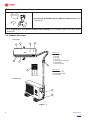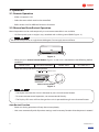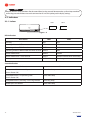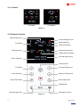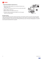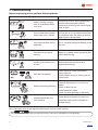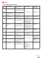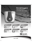
1
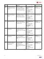
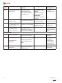
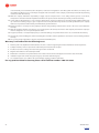
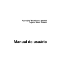
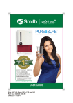
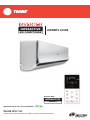
INTERACTIVE
AIR CONDITIONER
OWNER’S GUIDE
SPLIT AC WITH
INTERACTIVE
REMOTE
Applicable Series: IN 1 (Inverter Models) -
TRANE SPLIT AC
R410a
Pictures of the actual product may differ as per the product purchased.
Dear Customer
We are TRANE , a global leader in heating, ventilation and air conditioning equipment. We come
from the house of Ingersoll Rand , a $14 billion company with around hundred manufacturing
facilities worldwide. Our 1500 patents for heating, air conditioning and ventilation products are
testimony to our spirit of innovation. Today we bring innovation to your home.
At TRANE , we create products that are intuitive and easy to operate. They are simple, yet
technologically evolved for modern living. TRANE Interactive AC is one such product. The
TRANE Interactive AC assesses, manages and gives feedback on your in-home climate. The
ultra slim design brings together simplicity and elegance that complements your home. Once
it’s in your home, a whole new world of evolved living experiences will open up to you. The ‘Trane
mode’ optimizes comfort and efficiency. ‘Efficiency meter’ on the remote keeps you updated on
energy consumption, and therefore, keeps bills in check. The intelligent cooling sets the most
suitable temperature for your home by analyzing the temperature outside. TRANE AC creates
home environment that promises new levels of comfort, efficiency and convenience.
Welcome to the family of TRANE .
2
48663967 Rev 1
Contents
1. About this manual ............................................................................................................................................................................................ 4
1.1. Safety Information ...................................................................................................................................................................................... 5
1.2. Product Overview ..................................................................................................................................................................................... 10
2. Operation ............................................................................................................................................................................................................... 11
2.1. Remote Operation .................................................................................................................................................................................... 11
2.2. Manual and Auto Restart Operation............................................................................................................................................. 11
2.3. Indicators ....................................................................................................................................................................................................... 12
2.3.1. Indoor....................................................................................................................................................................................................... 12
2.3.2. Remote..................................................................................................................................................................................................... 13
2.4. Remote Controls ........................................................................................................................................................................................ 13
2.4.1. Range of Operation ............................................................................................................................................................................. 14
2.4.1.1. Lock and Indoor Unit range........................................................................................................................................................ 14
2.4.1.2. Remote and Indoor Unit range .................................................................................................................................................. 15
2.4.2. Functions ................................................................................................................................................................................................ 15
2.4.2.1. TRANE Mode ................................................................................................................................................................................. 15
2.4.2.2. Cool Mode ..................................................................................................................................................................................... 15
2.4.2.3. Dry Mode ....................................................................................................................................................................................... 15
2.4.2.4. Fan Mode ........................................................................................................................................................................................ 16
2.4.2.5. Sleep Mode .................................................................................................................................................................................. 16
2.4.2.6. Turbo Mode .................................................................................................................................................................................. 16
2.4.2.7. Fan speed ....................................................................................................................................................................................... 16
2.4.2.8. Night latch Mode (Only for units with “TRANE Lock”) .......................................................................................................... 16
2.4.2.9. Multi Room .................................................................................................................................................................................... 17
2.4.2.10. Swing Control.............................................................................................................................................................................. 17
2.4.2.11. Power ON and OFF ..................................................................................................................................................................... 17
2.4.3. Replacement of Batteries .................................................................................................................................................................. 17
2.5. Stabilizer Detail.......................................................................................................................................................................................... 18
3. Maintenance........................................................................................................................................................................................................ 18
3.1. Cleaning air filter....................................................................................................................................................................................... 18
3.2. Maintenance (Unit not in use for long duration) .................................................................................................................. 19
3.3. Checks before operation ...................................................................................................................................................................... 19
4. Troubleshooting .............................................................................................................................................................................................. 21
4.1. Error Messages and Actions ............................................................................................................................................................... 22
Warranty ....................................................................................................................................................................................................................... 25
3
48663967 Rev 1
1. About this manual
This manual is given as a guide to good practice for operating and periodic maintenance of TRANE Air
Conditioners.
This does not contain the full servicing procedures necessary for continued, or successful operation of
this equipment. The services of a qualified service personnel must be employed, through medium of
maintenance contract with a TRANE service company.
Do not operate before reading manual(s) supplied with this product.
Cautions as applicable are shown in this manual. Personal safety and proper operation of this unit
require that you follow them carefully. The manufacturer assumes no liability for installations or servicing
performed by unauthorised personnel. Always install, operate, inspect and maintain this product in
accordance with all applicable standards and regulations (local, state, country, federal, etc.). Keep this user
manual carefully for future reference.
4
48663967 Rev 1
Contents
1.1. Safety Information
Indicates a potentially hazardous situation which, if not avoided, could result in
serious injury.
Indicates a potentially hazardous situation which, if not avoided, may result in
minor or moderate injury or property damage.
Obey the following points to prevent electrical shock or fire:
Don’ts
t Do not remove power plug while the unit is in operation. It can
cause an electrical shock or fire.
t Do not operate this unit with wet hands. It can cause an
electrical shock.
t Do not pull power cord to remove power plug. It can cause
fire.
5
48663967 Rev 1
Contents
t Do not use longer power cord and/or share a same socket with
other electrical appliances. It can cause electrical shock or fire.
t Do not place flammable spray near this unit. It can cause
ignition and explosion.
t Do not insert or stick your hands into air intake or outlet
vents. It is dangerous and can cause injury.
t Do not spray or wash the unit with water. It can cause electrical
shock and/or malfunction of unit.
t Do not splash water on the unit. It can cause an electrical shock
and/or malfunction.
6
48663967 Rev 1
Contents
t Do not open windows and/or doors for long duration when
unit is ‘ON’. This will decrease the cooling performance.
t Do not splice power cord or use an extension cord. It can cause
fire or short circuit.
t Do not insert any objects or fingers into the outdoor unit fan.
It may cause unit failure and/or serious injury to the person.
t Do not touch the fins at the back side of outdoor unit. It can
cause injury.
t Do not step on top of outdoor unit. Falling off outdoor unit can
cause injury.
Do’s
t Make sure that all power supply connections are tight. Check
whether electrical grounding (earth) is complete. If not done,
it can cause electrical shock or fire.
7
48663967 Rev 1
Contents
t Turn off the power supply and pull out power connection
before cleaning. If not done it can cause electrical shock.
t Chemical agents such as Gasoline, benzene, thinner insecticides
etc., can damage this unit.
t Make sure installation stand is sufficiently firm. An unstable
stand can cause physical injury to the person damage or the unit.
t Operate this unit with stable voltage in range of 230 ± 10%,
single phase. If not done, compressor can vibrate and damage
refrigeration system.
t Use only fuse of correct capacity. Incorrect wire can cause
breakdown or fire.
Turn off
the power
supply
8
t If you detect burning smell or smoke, turn off power supply
and contact customer care centre immediately.
48663967 Rev 1
Contents
Don’ts
t Do not try to repair this unit. It can cause damage.
t Do not block air intake or outlet vents of both outdoor and
indoor units. It can decrease the performance of the unit or cause
malfunction.
e
m
t Do not keep remote on any metals, electronic or heating
devices like oven, TV, etc. for a longer period. It may decrease
the life of remote.
t Do not expose your body to cold air for a long duration.
It can cause deterioration in physical condition and health
problems.
t Do not use water at a temperature above 45 °C to clean, it can deform or discolour front panel.
t Do not dry filters near fire. It can ignite or deform them.
t Do not drop or throw remote control. It can cause malfunctioning or breakage.
t Do not use remote under direct sun light. It can create display issues.
9
48663967 Rev 1
Contents
Do’s
Run in the
Green Zone
t Set the unit at TRANE mode for efficient performance. It will
save energy.
e
t It is suggested to use TRANE recommended stabilizer. For stabilizers check with local TRANE
distributor.
1.2. Product Overview
Indoor unit
1
2
3
6
Indoor unit
4
1. Front panel
2. Air inlet
3. Air filter
4. Air outlet
5. Horizontal air flow grille
6. LED display
7. Remote control
5
8
Outdoor unit
7
8. Connecting pipe
9. Connecting cable
10. Stop valve
Outdoor unit
9
10
Figure - 1
10
48663967 Rev 1
Contents
2. Operation
2.1. Remote Operation
t Make sure power is ON
t Select the room which needs to be controlled.
t Refer section 2.4.2 for different functions of remote.
2.2. Manual and Auto Restart Operation
Manual operation can be used temporarily in case remote controller is not available.
t Lift Front panel up to an angle, it stays attached with a clicking sound (Refer Figure - 2).
Do not lift front panel at an angle above 60 degrees. Do not apply too much force.
Figure - 2
t When you press manual control button (Figure - 3), the unit is switched on at the following default
conditions
MODE: COOL
FAN SPEED: MEDIUM
SWING: AUTO
SET TEMP: 24 °C
t Lower the front panel to its initial position.
TSIXXMSXBSBCX Model Series
Manual control button
Figure - 3
t Use object not more than 5mm in diameter to press manual control button.
t To restore remote control operation, use remote control directly.
t The Display LED status will not change when unit is operated through manual control button.
Auto Restart Function
t Power cut during operation will stop the unit completely.
t Unit starts automatically with all previous settings saved in memory function when the power is restored.
11
48663967 Rev 1
Contents
Remote will be in sleep condition after 20 second from last key pressed. Remote wakes up from sleep condition
on first key pressed and does not sends command to AC unit and update just the display settings.
2.3. Indicators
2.3.1. Indoor
LED 1
LED 2
Figure - 4
LED Indication
Unit status
LED1
LED2
Stand by
RED
OFF
Stand by + Error on PCB
RED
RED
Operating without TRANE mode
GREEN
OFF
Operating without TRANE mode and Error on PCB
GREEN
RED
TRANE mode active
GREEN
GREEN
TRANE mode active + Error on PCB
GREEN
GREEN and RED Blinks alternately
Button press on remote
GREEN blink once
No change
Sound Indication
Unit status
Unit powered ON – in stand by state
Buzzer
One short beep
(Mains Power ON)
Unit powered ON – in operating state
One short beep
(Mains Power ON)
Unit powered OFF (stand by) / ON using remote
One long beep
Button press on remote
One short beep
12
48663967 Rev 1
Contents
2.3.2. Remote
e
e
User Mode
Trane Mode
Figure - 5
2.4. Remote Controls
Room Temperature
Acvtivated Night Latch
Mode Indication
Fan Speed
Sleep/Turbo Mode
Set Temperature
Outdoor Temperature
e
Energy Efficiency Meter
Error Message Display
Room Selection
Power ON/OFF
Increase Temperature
Fan Speed
Decrease Temperature
Louver Direction
Sleep/Turbo Mode
Mode Adjustment
TRANE Mode
Remote Night Latch
Multi Room Control
Figure - 6
13
48663967 Rev 1
Contents
Symbol
Button
Function
Display
Description
Fan speed
adjustment
Air flow rate adjustment.
Swing
adjustment
Changes the air flow
direction
SLEEP /
TURBO mode
activation
Toggles between SLEEP,
TURBO and Default.
Temperature
UP/DOWN
Increase and decrease the
set temperature
Mode
Adjustment
Changes the mode as such,
press once for COOL, twice
for DRY and thrice for FAN.
TRANE Mode
Activates TRANE mode
Refer Figure - 5
Activates TRANE mode
Power
ON/OFF
NA*
ON/OFF
Night
latch mode
activation/
deactivation
Activates/deactivates
night latch mode on TRANE
lock.
Shows night latch mode
selection
Multi room
(Room
Configuration)
Selects the split air
conditioner to control.
Shows room selection as
for each room AC settings
-
NA*
-
Indicates error
-
NA*
-
-
NA*
-
Shows current outdoor
ambient temperature.
-
NA*
-
Shows current room
temperature.
Shows fan speed
Changes the air flow
direction
NA*
Shows mode selection
(SLEEP/TURBO)
/
Shows temperature
selection
/
e
Shows mode selection
(COOL/DRY/FAN)
/
Shows different efficiency
zone (Refer section
2.4.2.2)
* NA: Not Applicable
2.4.1. Range of Operation
2.4.1.1. Lock and Indoor Unit range
14
Range (Indoor)
Range (Outdoor - without any obstacles)
15 meter
1000 meter
48663967 Rev 1
Contents
2.4.1.2. Remote and Indoor Unit range
Range (Indoor)
Range (Outdoor - without any obstacles)
14 meter
160 to 175 meter
2.4.2. Functions
2.4.2.1. TRANE Mode
1. Press
to start or stop TRANE mode (Refer Figure - 7).
2. The unit when powered ON by remote control starts with TRANE mode by default.
3. The TRANE mode will set room temperature and fan speed automatically to provide
an energy efficient and comfortable environment hence the energy efficiency
meter always shows dark green (Refer Figure - 5)
Figure - 7
4. It will set room temperature automatically based on outdoor temperature.
5. Unit shall exit ‘TRANE mode’ if user changes any of the following: set point, fan speed, mode, sleep and
also if
button is pressed.
6. Unit will not exit ‘TRANE mode’ if user changes any of the following:
swing button,
multi room or
night latch button.
7. The indication of TRANE mode is
button with red back light and the remaining buttons with light
OFF. The back light will go OFF after 20 seconds from last operation of remote controller.
2.4.2.2. Cool Mode
1
COOL
2
3
DRY
e
FAN
Display
Figure - 8
1. Press MODE
to select cool mode, see ‘COOL’ shown on display (Refer Figure - 8).
2. Press
to set fan speed (if required)
3. Press
or
to increase or decrease set temp. Set temperature range is 17°C - 30°C.
This is normal mode of cooling. User can set room temperature and AC will run to
attain the set temperature.
Temperature can be set based on energy consumption, Refer below table
Zone 1 - Red
Uneconomical
Zone 2 - Yellow
Higher energy consumption
Zone 3 - Light green
Economical
Zone 4 - Dark green
3
2
4
1
e
Figure - 9
Lower energy consumption
2.4.2.3. Dry Mode
1. Press MODE
to select dry mode, see ‘DRY’ shown on display
(Refer Figure - 10).
1
In dry mode default set temperature is 25°C.
e
Set temperature and fan speed cannot be changed.
Unit will operate at low fan speed for maximum moisture removal.
Display
Figure - 10
15
48663967 Rev 1
Contents
In high humidity conditions, user can select dry mode.
1
2.4.2.4. Fan Mode
1. Press MODE
to select fan mode, see ‘FAN’ shown on display.
e
Set point temperature cannot be adjustable.
Fan speed can be adjustable.
Figure - 11
2.4.2.5. Sleep Mode
1. Press
to activate sleep mode operation.
The ‘set’ temperature will automatically increase by 1°C for each
hour for four hours.
After 4 hours unit will stay at latest temperature. E.g., if the
set temperature is 24°C and sleep mode is started. After first hour
set temperature will increase to 25°C and at the end of fourth hour
set temperature will be at 28°C. The unit will stay at 28°C.
Press
again to disable sleep mode.
Set point temperature and fan speed can be adjustable.
2.4.2.6. Turbo Mode
1. Press
to activate turbo mode. See ‘TURBO’ on remote display.
Display
1
e
Figure - 12
Display
1
Enables instant cooling by automatically adjusting fan speed to
turbo level.
e
Fan speed cannot be changed while unit is in turbo mode.
The display will not show the fan speed bar (Refer Figure - 13).
Figure - 13
User can set this mode for fast cooling.
Press
again to disable turbo mode.
Display
1
2.4.2.7. Fan speed
1. Press fan speed
to change fan speed.
e
Fan speed can be changed as below
Low
Medium
High
Auto
Figure - 14
Display
Fan speed is adjusted automatically according to set point and
room temperature when FAN speed is set to AUTO mode.
2.4.2.8. Night latch Mode (Only for units with “TRANE Lock”)
LOCK
AC Remote
Night latch Mode
Ac!va!on/Deac!va!on
Away
Home
Passage
Night Latch
e
Press Twice
Display
Figure - 15
16
48663967 Rev 1
Contents
1. Press
on remote to activate or deactivate night latch mode on lock. Night latch
will show on
remote display after it started (approximately 30 seconds for display to update).
2. When night latch key pressed on remote, displays message “ENABLING NIGHT LATCH PLEASE WAIT”.
After night latch mode activated,
and the confirmation message “NIGHT LATCH ENABLED” will be
displayed.
3. When night latch key pressed on remote to disable the night latch, displays message “DISABLING
NIGHT LATCH PLEASE WAIT”. After night latch mode deactivated, confirmation message “NIGHT
LATCH DISABLED” will be displayed and night latch
will disappear.
4. Night latch mode helps user to prevent access to home even with valid credential. Night latch mode
operates only when Lock and AC are connected on network.
5. Refer lock manual for night latch mode features.
2.4.2.9. Multi Room
1. Press
1
to activate multi room feature.
Multi room feature allow user to select and control two or more
AC’s with one remote from one room.
Press
to switch and control AC in network.
Name of selected AC and its current settings shown on remote display.
2.4.2.10. Swing Control
e
Display
Figure - 16
Deflector rod
Figure - 17
1. Use swing
to adjust air flow direction. The horizontal louver changes direction at defined angle
and auto swing. Vertical louver can only be adjusted manually. Move deflector rod manually to adjust
air flow direction.
2. Adjust air flow direction properly otherwise it can cause discomfort or uneven room temperatures.
2.4.2.11. Power ON and OFF
1. Press ON/OFF button to switch ON/OFF the unit. When power is ON, the unit operate in TRANE mode
by default.
2. Remote back light will glow in red
.
2.4.3. Replacement of Batteries
t Do not use combination of old and new batteries. Life of battery is more than six months in
normal usage.
t To prevent batteries from leakage of electrolyte and damaging controller, remove the batteries,
if not using for long duration.
t Batteries are to be replaced when “Low Battery” error is shown on display.
t To Replace Batteries,
t 4MJEFCBDLDPWFSBOESFNPWFPMECBUUFSJFT
t 6TFUXPOFX"""BMLBMJOFCBUUFSJFT3FDPNNFOEFE%VSBDFMM¥# ‘AAA’ batteries rated 1.5V)
t #BUUFSZ1PMFTNVTUBMJHOXJUIJOTUBMMBUJPOQPTJUJPO3FGFS'JHVSF
# Registered trademark of Duracell, P&G Inc.
17
48663967 Rev 1
Contents
Risk of explosion if batteries are replaced by an incorrect type. Dispose of used batteries according to the
instructions provided on the batteries.
1
2
3
Figure - 18
2.5. Stabilizer Detail
AC Tonnage
Stabilizer KVA
1.0
3
1.5
4
2
5
3. Maintenance
3.1. Cleaning air filter
Clogged air filter decreases cooling efficiency. Clean filter at interval of two weeks.
Disconnect power supply before cleaning indoor unit.
1
Support pole
t Lift Front panel up to an angle, keeping it attached
until it makes a clicking sound.
t Clean units with soft, dry or moist cloth with water
or cleanser.
t Use support pole to hold the front panel at its place
after lifting it.
18
48663967 Rev 1
Contents
2
t Hold the air filter handle and lift slightly to release
it from holder, pull downwards to remove air filter
from indoor unit.
Filter Handle
3
t Clean air filter with a vacuum cleaner or water, dry
in cool place.
Air freshening filter
4
t Remove air freshening filters from its supporting
frame. Clean air freshening filter monthly, and
replace at an interval of 4-5 months.
t Install air freshening filter into its original
position.
5
t Insert upper part of air filter and place filter into
position, make sure left and right edges align
correctly.
3.2. Maintenance (Unit not in use for long duration)
If you do not plan to use unit for a long time, perform following actions:
t Clean indoor unit and filters.
t Operate fan for approximately 30 minutes in order to dry inner side of unit.
t Switch OFF the unit.
t The outdoor unit requires periodic maintenance and cleaning. The user must not do periodic
maintenance of product on their own. Contact dealer or service provider.
3.3. Checks before operation
t Make sure wiring is not broken or disconnected.
t Make sure air filter and front panel are installed.
t Make sure air outlet or inlet is not blocked.
If air filter screen is blocked by dust or dirt, the performance of the unit will be affected, with higher
operation noise and power consumption. Air filter screen should be cleaned regularly.
19
48663967 Rev 1
Contents
Preparation before season of use
1. Be sure that nothing obstructs air outlet and intake vents.
(Refer Figure - 19)
2. Examine whether ground (earth) wire is correctly connected.
3. Replace filters if necessary.
4. Replace batteries of remote if necessary.
5. Examine mounting bracket of outdoor unit, if damaged
contact servicing agency.
Figure - 19
Ground wiring
Connect Ground wire to exclusive device correctly, if not employ specialist to install. Grounding pole of
socket should be grounded and wired reliably, breaker and air switch with enough capability should be
installed in fixed lines. Do not connect grounding cable to gas pipe, water pipe, sewage pipe or any other
areas deemed unreliable for this purpose.
20
48663967 Rev 1
Contents
4. Troubleshooting
Before requesting service, perform following checks.
Symptom
Waiting
Remedy
Indoor unit does not give
cool air immediately when
unit starts.
Compressor restarts after approximately
three minutes to protect itself. On
compressor restarting units starts to give
cool air again
Unusual odor blowing from
outlet when unit is started.
Open the door or window for 2 minutes
and run the AC in Fan mode to allow fresh
air inside the room. This helps to remove
odors from inside the room.
Sound of water flow during
operation.
This is caused by refrigerant flowing inside
the unit.
Formation of mist while
cooling.
Room air is cooled quickly by cold air flow
which looks like fog.
Creaking noise during start
or stop.
Deformation of plastic because of
temperature change.
Unit does not operate.
Check electrical system connections,
cords and fuses.
Check if power supply is within 10% of
rated supply.
Decreased cooling efficiency.
Check ‘set temperature’.
Check for obstructions in air inlet and
outlet.
Check air filters for dirt.
Check indoor fan speed.
Check any other openings in the room.
Remote control does not
work correctly.
Check effective distance to indoor unit.
Check low battery error indication on
remote display.
If the trouble has not been corrected, please contact a local dealer or the nearest customer service centre.
Be sure to inform them of the detailed malfunctions and unit model number.
Do not attempt to repair the unit yourself. Always consult an authorized service provider
21
48663967 Rev 1
Contents
4.1. Error Messages and Actions
Error
codes
Error Description
Error Displayed on
Remote
0x01
EEPROM
communication error
Error 01 EEPROM
communication error -Please Contact Customer
Care
Unit Response
Unit Stops Working
Action to be
Taken by user
Contact
Customer Care
0x02
Compressor Failure
error or refrigerant
leakage
Error 02 OutDoor Unit
Error -- Please Contact
Customer Care
0x03
Filter choke Error
Error 03 Filter choke error
-Clean the filter
Unit Operates as per
user settings
Clean Filters
0x04
Indoor Room
temperature sensor
error
Error 04 Room temp
sensor failure -- Please
Contact Customer Care
Cool mode or Dry
mode: Unit operate
with Compressor OFF.
Fan mode: Operates
as per user setting
Contact
Customer Care
0x06
Indoor coil
temperature sensor
error
Error 06 Indoor temp
sensor failure -- Please
Contact Customer Care
Cool mode or Dry
mode: Unit operate
with Compressor OFF.
Fan mode: Operates
as per user setting
Contact
Customer Care
0x08
Communication error
Error 08 Communication
error -- Please Contact
Customer Care
Stop indoor unit and
outdoor unit
Contact
Customer Care
0x09
Low battery
Error 09 Low battery
please change the
battery
Operates indoor unit
and outdoor unit as
per user setting.
Change battery
0x0A
Input Power Error
Error 10 IDU Input
Power Problem -- Please
Contact Customer Care
0x0B
IDU Error - Fan failure
Error 11 IDU Error - Fan
Failure -- Please Contact
Customer Care
0x0D
Communication error
(IDU to ODU)
Error 13: Communication
error (IDU to ODU) -Please Contact Customer
Care
22
Unit stops working
Cool mode or Dry
mode:
Unit will run with
Compressor OFF.
Fan mode:
Run IDU as per user
settings.”
Check the power
cord / Contact
Customer Care
Contact
Customer Care
Contact
Customer Care
48663967 Rev 1
Contents
Error
codes
Error Description
Error Displayed on
Remote
Unit Response
Action to be
Taken by user
0x0E
Outdoor discharge
temperature sensor
error
Error 14: Outdoor
discharge temperature
sensor error -- Please
Contact Customer Care
Cool mode or Dry
mode:
Unit will run with
Compressor OFF.
Fan mode:
Run IDU as per user
settings.”
Contact
Customer Care
0x0F
Outdoor EEPROM
parameter reading
error
Error 15 : Outdoor
EEPROM parameter
reading error -- Please
Contact Customer Care
Cool mode or Dry
mode:
Unit will run with
Compressor OFF.
Fan mode:
Run IDU as per user
settings.”
Contact
Customer Care
0x13
IPM module failure
Error 19: IPM module
failure -- Please Contact
Customer Care
Cool mode or Dry
mode:
Unit will run with
Compressor OFF.
Fan mode:
Run IDU as per user
settings.”
Contact
Customer Care
0x14
High/ Low Voltage
protection
Error 20 :High/ Low
Voltage protection -Please Contact Customer
Care
Cool mode or Dry
mode:
Unit will run with
Compressor OFF.
Fan mode:
Run IDU as per user
settings.”
Contact
Customer Care
0x17
Compressor position
protection
Error 23:Compressor
position protection -Please Contact Customer
Care
Cool mode or Dry
mode:
Unit will run with
Compressor OFF.
Fan mode:
Run IDU as per user
settings.”
Contact
Customer Care
0x1A
Outdoor Condenser
coil temperature
sensor error
Error 26: Outdoor
Condenser coil
temperature error -Please Contact Customer
Care
Cool mode or Dry
mode:
Unit will run with
Compressor OFF.
Fan mode:
Run IDU as per user
settings.”
Contact
Customer Care
23
48663967 Rev 1
Contents
Error
codes
Error Description
Error Displayed on
Remote
Unit Response
Action to be
Taken by user
0x1E
Outdoor temperature
sensor error
Error 30: Outdoor
Temperature sensor
error -- Please Contact
Customer Care
Cool mode or Dry
mode:
Unit will run with
Compressor OFF.
Fan mode:
Run IDU as per user
settings.”
Contact
Customer Care
-
Remote not in
network range
NETWORK NOT FOUND
Unit operates as per
previous settings.
Remote must be
in network range
-
Connect to network (if
user did factory reset
on the remote)
CONNECT TO NETWORK
Unit operates as per
previous settings
Contact service
technician
-
AC switched OFF
(main power OFF)
SET POINT TEMP +
INFRARED ACTIVATED +
NO NETWORK FOUND
Switch ON main
power/check the
plug
Lock not installed
NIGHT LATCH FAILED -LOCK NOT INSTALLED
Lock is not in
network
-
Night latch not
operating
NIGHT LATCH FAILED -PLEASE CHECK YOUR
LOCK
Change Battery
of Lock or
Check Lock is
in Network by
doing Home/
Away Operations
-
Door Open
NIGHT LATCH FAILED -DOOR OPEN
Close door
Lock with AC
-
Refer Section 2.3.1 for LED indications
24
48663967 Rev 1
Contents
Warranty
Terms & Conditions
Ingersoll-Rand (hereinafter referred to as ‘the company’) warrants to the purchaser that this TRANE split air conditioner (“Product”) carries a
warranty for the period mentioned above, commencing from the date of purchase. The company will repair or replace free of charge any part or
parts of the Product, if the defect is due to the defective material or workmanship. Warranty involves repairing of defective product/parts and
does not entitle the purchaser for the replacement for a new product.
Preventive Maintenance:
Maintenance check up will be carried out 2 times in a period of 12 months from the date of invoice on request from the customer and will
include:
t
t
t
General cleaning and brushing up of dirt and muck.
Cleaning of air filter.
Checking of electronic parts and its contacts.
Breakdown Complaints
t Company will put in reasonable
efforts to promptly attend to any breakdown complaint lodged by the customer at company’s
authorized sales and service dealer or branch office or at the centralized customer care centre.
Compressor Warranty Clause:
The 5 year compressor warranty will continue even after the expiry of 1 year period from the date of purchase. This warranty covers the
compressor only. Gas charging is included only when the compressor is defective & inoperative. During the additional warranty period it does
not cover parts or any part such as
t
t
t
t
t
Condenser Coil
Evaporator Coil
Capillary
Suction Line
Electronic Parts
Other terms
1. This warranty is confined to the first Purchaser of the Product only & is non transferable.
2. The warranty for both machine and compressor will terminate upon expiry of the warranty period irrespective of whether or not the
Product has been in use for any reason whatsoever.
3. The warranty for both Product and the compressor will automatically be terminated on the date of expiry of the warranty period. No
notice of expiry of warranty will be given at any time.
4. Compressor warranty will be applicable only if the Product is maintained by authorized dealers of the company.
5. For Products installed beyond the municipal limits of the jurisdiction of the authorized service centre/company’s service centre/
authorized dealer’s service centre, all expenses incurred in collection of the Product or part/s thereof from the company’s service
centre/authorized service centre/authorized dealer’s service centre, as well as expenses incurred in connection with deputing of service
personnel/ technicians towards to and fro travel, conveyance and other incidentals etc. (together referred to as “Transportation and
Handling Expenses”) shall be borne by the Purchaser.
6. The company or the authorized sales and service dealer will advise the Purchaser whether to effect repairs/replacement at the site of
installation or at the company or authorized sales and service dealer’s premises and the decision of the representative shall be final.
7. The company reserves the right to replace the defective part with a substitute equivalent part without affecting the performance of
the Product.
8. In case of any transit damage, the Product shall be repaired by the concerned service centre on charges and warranty for the unexpired
period will continue.
9. In the event of repairs/replacement of any part/s of the Product, this warranty will thereafter continue and remain in force only for
the unexpired period of the warranty. Moreover, the time taken for repair/replacement and in transit whether under the warranty or
otherwise shall not be excluded from the warranty period.
10. The warranty extended herein is in lieu of implied conditions and warrants under the law & is confined to the repair or replacement of
defective parts and does not cover any consequential or resulting liability, damage or loss arising from such defects. Also, the warranty in
no case shall extend to payment of any monetary consideration whatsoever or replacement or return of the Product as a whole.
11. The company’s obligation under this warranty shall be limited to repair or providing replacement of part/s only. The maximum claim/s
if entertained by the company will be subject to the maximum retail price of the Product purchased or the purchase price, whichever
is lower.
12. Any change of Address of the purchaser will be intimated to the concerned service centre/dealer for continuation of warranty.
13. The company shall not be liable or deemed to be in default for any delay or failure in performance resulting directly or indirectly from
causes beyond its reasonable control including delay in repairing due to non-availability of any part/component, labour problem,
presence of any foreign object or living creature (e.g. Rat, lizard, Insects, Ants etc.) inside the unit, use of harmful chemicals, usage of unit
25
48663967 Rev 1
Contents
in an abnormally corrosive alkaline/acidic atmosphere, restrictions and regulations of the Govt., public movement, war and any other
unavoidable circumstances vis-a-vis the import of supplies and raw material or if the company is otherwise prevented from performing
its functions under this warranty.
14. While the company undertakes responsibility to supply only the compressor free of cost during warranty period, cost of labour,
transportation and other incidental expenditures shall be borne by the customer after the lapse of first year Product warranty.
15. In areas where voltage fluctuates +/-10% of rated or usable voltage, customer is advised to use a branded voltage stabilizer which steps
up or down the incoming voltage to give an output of 230V. For any fluctuation beyond the reasonable specified limit, the company
shall not be responsible and this warranty shall immediately stand terminated.
16. Earthing provision is necessary for safety. Improper domestic wiring leading to hazards such as shock or fire is not covered under this
warranty.
17. While the Company will make every effort to carry out the repairs at the earliest, it however is made expressly clear that the company is
under no obligation to do so in a specified period of time.
18. Any special, indirect or consequential property or commercial damage of any nature whatsoever is not covered under this warranty.
19. The warranty is issued at Bangalore, and Courts at Bangalore shall have exclusive jurisdiction over matters covered or flowing from this
warranty.
20. The 1 year warranty is applicable to all parts except for Plastic & Rubber parts.
Warranty is null and void in the following cases:
1.
2.
3.
4.
5.
6.
7.
Warranty card is not duly filled and mailed back to the service centre for registering the Product within three months of purchase.
Complete warranty card is not presented to authorized personnel at the time of repair.
Product is not used according to the instructions given in the user manual.
Original serial number is removed/tampered with.
Modification or alteration of any nature whatsoever is made in the electrical circuit/physical construction of/to the Product.
Installation/repair work carried out by person/agency other than authorized agency.
Site conditions that do not confirm to the recommended operating conditions of machine.
For any product related assistance, please call on Toll free number: 1800 102 9986.
26
48663967 Rev 1
Contents
Corporate Office: Plot No.35, KIADB Industrial Area, Bidadi, Ramanagaram Taluk,
Bangalore-562109, Karnataka, INDIA. www.traneindia.com
For more information call on 1800 102 9986
48663967 | Edition 2 | January 2013
or write to [email protected]