1
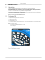
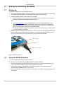
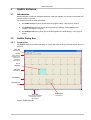
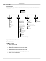
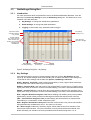
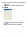
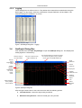
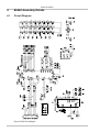
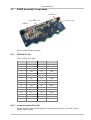
LQ
w w w . q p r o x . c o m
E6240
User Manual
The New Vision of TouchTM
E6240 User Manual
Contents
1
E6240 Overview........................................................................................................................ 3
1.1
1.2
Introduction ....................................................................................................................................................................................3
Contents of Kit ...............................................................................................................................................................................3
2
Setting Up and Using the E6240 ............................................................................................. 4
2.1
2.2
Setting Up ......................................................................................................................................................................................4
Using the E6240 Assembly............................................................................................................................................................4
3
QmBtn Software ....................................................................................................................... 5
3.1
3.2
Introduction ....................................................................................................................................................................................5
QmBtn Dialog Box .........................................................................................................................................................................5
3.2.1
3.2.2
3.2.3
3.2.4
3.2.5
3.3
Introduction ................................................................................................................................................................................................5
Menu Bar....................................................................................................................................................................................................6
Toolbar .......................................................................................................................................................................................................8
Keys Area...................................................................................................................................................................................................8
Status Bar...................................................................................................................................................................................................8
QmSettings Dialog Box..................................................................................................................................................................9
3.3.1
3.3.2
3.3.3
3.3.4
Introduction ................................................................................................................................................................................................9
Key Settings ...............................................................................................................................................................................................9
Global Settings.........................................................................................................................................................................................10
Logging.....................................................................................................................................................................................................11
3.4
QmGraph Dialog Box...................................................................................................................................................................11
4
E6240 Assembly Details ........................................................................................................ 12
4.1
4.2
Circuit Diagram ............................................................................................................................................................................12
E6240 Assembly Components.....................................................................................................................................................13
4.2.1
4.2.2
4.2.3
4.2.4
4.2.5
4.2.6
5
QT60240 IC (U1)......................................................................................................................................................................................13
Communications Port (J2)........................................................................................................................................................................13
USB Connector (J3) .................................................................................................................................................................................14
LEDs.........................................................................................................................................................................................................14
Scope Sync ..............................................................................................................................................................................................14
Mains Sync...............................................................................................................................................................................................14
Troubleshooting..................................................................................................................... 15
List of Figures
Figure 1: E6240 Evaluation Assembly .............................................................................................................................................................................3
Figure 2: E6240 Connections...........................................................................................................................................................................................4
Figure 3: QmBtn Dialog Box.............................................................................................................................................................................................5
Figure 4: QmBtn Software Menu Structure ......................................................................................................................................................................6
Figure 5: QmSettings Dialog Box – Key Settings.............................................................................................................................................................9
Figure 6: QmSettings Dialog Box – Global Settings ......................................................................................................................................................10
Figure 7: QmSettings Dialog Box – Logging ..................................................................................................................................................................11
Figure 8: QmGraph Dialog Box ......................................................................................................................................................................................11
Figure 9: E6240 Circuit Diagram ....................................................................................................................................................................................12
Figure 10: E6240 Evaluation Assembly .........................................................................................................................................................................13
List of Tables
Table 1: QT6240 IC (32-QFN)........................................................................................................................................................................................13
Table 2: Communications Port (J2)................................................................................................................................................................................14
2 of 17
E6240 User Manual
1
E6240 Overview
1.1
Introduction
This kit is designed for the evaluation and development of applications using the
QT60160/QT60240 IC. The kit includes an evaluation assembly (E6240 – see Figure 1), cables
and QmBtn software. Each E6240 assembly has a serial (USB) interface allowing connection to a
computer for control and data viewing via QmBtn computer software.
This unique IC allows designers to create controls for various applications such as mobile phones,
remote controls and MP3 players, amongst others.
Refer also to the QT60160/QT60240 datasheet.
1.2
Contents of Kit
1 x E6240 assembly (fitted with a QT60240 IC)
1 x USB-computer cable
2 x sample QT60240 ICs
1 x CD-ROM containing QmBtn software version 3.29 or later, User Manual and other information
Note: you will also need:
a computer with Windows 2000, XP or later
a free USB port
Figure 1: E6240 Evaluation Assembly
3 of 17
E6240 User Manual
2
Setting Up and Using the E6240
2.1
Setting Up
To prepare the E6240 for use, proceed as follows:
1. Using the USB cable provided, connect the E6240 to the computer (see Figure 2). Both LEDs
on the E6240 light constantly to indicate that there is power to the assembly.
2. Install the QmBtn software; either method is acceptable:
a. Put the supplied CD in the CD drive of the computer. Copy the contents of the CD to the
computer. Double-click the QmBtn software to open it.
OR
b. Go to www.qprox.com, point to the Support tab and click Download Archive. Click
Software and then the qmbtn (version 3.28 or later) link for the E6240. A dialog box
appears asking if you want to run or save the file that you are about to download. Click
Run. This automatically downloads the QmBtn software.
If a dialog box appears saying “The publisher could not be verified. Are you sure you want
to run this software?” click Run.
3. QmBtn software is displayed on the computer monitor. One LED is extinguished and the other
flickers continuously to indicate that the software is communicating with the E6240. Refer to
Section 2.2 and Section 3 for information about using the E6240 and QmBtn.
LED1 and LED2
Connector J2
USB cable to computer
Figure 2: E6240 Connections
2.2
Using the E6240 Assembly
1. Place the E6240 assembly on a level surface.
2. Keeping clear of the E6240, click Recall All on the QmBtn software.
3. Touch any key area on the E6240. Every time a key area is touched the corresponding key
area on the QmBtn software turns blue for the duration of the touch.
4. If the QmBtn software is not detecting, or detection is sporadic, decrease the detection
threshold slightly (NTHR, Section 3.3.2, page 9).
5. Refer to Section 3.3.2, page 9 and Section 3.3.3, page 10 for details of which parameters you
can change.
4 of 17
E6240 User Manual
3
QmBtn Software
3.1
Introduction
QmBtn software is used with the E6240 assembly. With this software you can send commands and
monitor signals in real time.
The program consists of three main areas:
•
•
•
the QmBtn dialog box (which opens when the program starts – see Figure 3, page 5)
the QmSettings dialog box (which has three tabs, Key Settings, Global Settings and
Logging – see Figure 5, page 9)
the QmGraph dialog box (which gives real-time signals for individual keys) – see Figure 8,
page11
3.2
QmBtn Dialog Box
3.2.1
Introduction
The QmBtn dialog box provides the ability to monitor the status of all keys and the overall device in
real time.
Menu Bar
(see Page 6)
Toolbar
Allows various
functions of the
E6240 to be
performed
(see Page 8)
Key in
Detection
Keys Area
(see Page 8)
Key Number
Key Reference
Level
Key Disabled
(see Page 9)
Status Bar
Shows connection details
and firmware version
(see Page 8)
Figure 3: QmBtn Dialog Box
5 of 17
E6240 User Manual
3.2.2
Menu Bar
Menu Structure
Refer to Figure 3, page 5 for the location of the Menu bar and Figure 4 for the menu structure and
commands.
QmBtn
File
Options
View
Help
New
Beep on Key Down
Key Settings...
Help
Open...
Beep on Key Up
Graph...
About QmBtn...
Save
Read After Write
Key Numbers
Save As...
Reset After Write
Key Reference Levels
Recent File
Calibrate After Write
Detailed Status Below Keys
Exit
Start/Stop Data Log...
Toolbar
QmSettings...
Advanced
Status Bar
QmGraph...
Join Data Points
Save Options on Close
Communications...
Port
Baud Rate
Interface
Device
Send Keystrokes to Another App...
Figure 4: QmBtn Software Menu Structure
Menu Commands
File Menu: Click File,
•
New to create a new file
•
Open to open a *btn file
•
Save to save the setup of the IC in the current *btn file
•
Save As to save the setup of the IC in a new *btn file
•
Recent File to see a list of the most recently used *btn files
•
Exit to close the QmBtn software
6 of 17
E6240 User Manual
Options Menu: Click Options,
•
Beep on Key Down to generate a computer beep on key activation
•
Beep on Key Up to generate a computer beep on key release
•
Read After Write to automatically send a read command after sending a new setup block
•
Reset After Write – not available
•
Calibrate After Write to automatically send a recalibrate command after sending a new
setup block
•
Start/Stop Data Log to record data into a *csv file
•
QmSettings
Advanced to display advanced key settings
•
QmGraph
Join Data Points to draw the graph using a solid line
•
Save Options on Close to save software settings on closing the software
•
Communications
Port to select the USB/COM port
Baud Rate to select the baud rate
Interface to select the type of interface
Device to select the type of QT device
•
Send Keystrokes to Another Application to send keystrokes code to another application
View Menu: Click View,
•
•
•
•
•
Key Settings to open the QmSettings dialog box
Graph to open the QmGraph dialog box for a particular key (i.e. the last key which was
clicked in the software)
Key Numbers to turn the display of key numbers in the QmBtn dialog box on/off
Key Reference Levels to turn the display of key reference levels in the QmBtn dialog box
on/off
Detailed Status Below Keys to turn the display of device status information in the QmBtn
dialog box on/off
•
Toolbar to turn the toolbar in the QmBtn dialog box on/off
•
Status Bar to turns the status bar in the QmBtn dialog box on/off
Help Menu: Click Help,
•
Help to open the Help file
•
About QmBtn to see details of the copyright and software version
7 of 17
E6240 User Manual
3.2.3
Toolbar
The toolbar can be displayed or hidden by use of a command in the View menu (see page 7). It
has the following buttons:
3.2.4
•
Click Send to transfer a new setup block to the IC
•
Click Read to obtain the current setup parameters
•
Reset – not available
•
Click Recal All to recalibrate all the keys
Keys Area
The QT60160 can have a maximum of 16 keys enabled and the QT60240 a maximum of 24 keys
enabled. These keys can be anywhere in the 8 x 3 matrix. QmBtn depicts the keys, showing the
key numbers and the key reference levels.
If a key area on the E6240 is touched then the corresponding key area on the QmBtn turns blue for
the duration of the touch. If a key is disabled the corresponding key area on the QmBtn appears
shaded, with a criss-cross pattern (see Figure 3).
3.2.5
Status Bar
The status bar can be displayed or hidden by use of a command in the View menu (see page 7). It
shows which device is connected to the computer, the IC revision and the type of interface.
8 of 17
E6240 User Manual
3.3
QmSettings Dialog Box
3.3.1
Introduction
For more information about the parameters refer to the QT60160/QT60240 datasheet. From the
Menu bar click View, Key Settings to open the QmSettings dialog box. This allows the IC to be
modified. There are three tabs:
•
Key Settings: to change the individual key parameters
•
Global Settings: to change the global parameters
•
Logging: to select which keys’ parameters will be logged
Click here to make
changes to all keys
Key settings
(Section 3.3.2)
Key number
To select multiple
keys, press and hold
CTRL and then click
the keys. The changes
will apply to all
selected keys
Value becomes
bold when changed
Key Settings
(for individual keys)
Logging
Global Settings
(for recording data)
(for all keys)
Figure 5: QmSettings Dialog Box – Key Settings
3.3.2
Key Settings
If the dialog box does not open in the Key Settings view then click the Key Settings tab (see
Figure 5). The default settings show NTHR and BL (with no tabs at the bottom of the dialog box).
To see the full list of settings and the tabs click Options, QmSettings, Advanced.
NTHR – Negative Threshold is used to adjust the sensitivity of a key. Higher values make keys
less sensitive, lower values make keys more sensitive.
NDRIFT – Negative Drift is the rate at which drift compensation is carried out for a negative going
signal (when a key is touched or receives increased loading). The value is seconds/reference level.
PDRIFT – Positive Drift is the rate at which drift compensation is carried out for a positive going
signal (when a key is touched or receives increased loading). The value is seconds/reference level.
NDIL – Negative Detection Integrator Limit allows enabling and disabling of keys and provides
signal filtering. Higher values provide more filtering but increase the response time of the key.
FDIL – Fast Detection Integrator Limit provides filtering but has less effect on response time.
Total filtering is a combination of NDIL multiplied by FDIL.
NRD – Negative Recalibration Delay determines the maximum time a key can be active before
being automatically recalibrated by the IC. The value is in seconds.
BL – Burst Length modifies key sensitivity. Higher values make the key more sensitive, lower
values make it less sensitive. The correct sensitivity for a key should be achieved with BL and
NTHR. Generally, BL should be as low as possible and NTHR should range from 7 to 12.
9 of 17
E6240 User Manual
AKS – Adjacent Key Suppression can be enabled or disabled. To become active, a key with this
option enabled must receive the strongest signal relative to other AKS-enabled keys.
Scope Sync – sends a positive pulse that brackets the burst of a selected key. This feature is
invaluable for diagnostics.
WH – Wake allows the device to be configured to wake up when specific keys are touched. Each
key has its own configuration bit so that any combination of keys can be configured for this
purpose.
3.3.3
Global Settings
If the dialog box does not open in the Global Settings view then click the Global Settings tab
(see Figure 6).
Figure 6: QmSettings Dialog Box – Global Settings
Mains Sync – allows the part to synchronise on the low frequency signal. This is generally used to
synchronise acquisition on the mains cycle (50/60Hz). The frequency must be more than 10Hz.
Sleep Duration – defines the length of time the device will sleep before automatically waking up
and returning to sleep.
Awake Timeout – defines the minimum amount of time the part will stay awake after a
communication or after a valid key press woke it up.
Drift Hold – defines the time the drift on the reference is held after a key is touched. This affects all
the keys. If set to Off all keys drift regardless of the state of other keys.
10 of 17
E6240 User Manual
3.3.4
Logging
These settings have no effect on the IC. They define which data will be recorded when using the
Data Logger. For any key(s), select any combination of Signal, Reference, DI and Status. The
selected readings are recorded in a *csv file.
Figure 7: QmSettings Dialog Box – Logging
3.4
QmGraph Dialog Box
From the Menu bar click View, Key Settings to open the QmGraph dialog box. This displays the
analog signal for a selected key.
Sets the origin for
the vertical scale
Sets the Y reference level
origin to default (110)
The QmGraph dialog box shows the signals
for a specific key (select a key by clicking
the key area in the QmBtn dialog box)
Sets the
signal
magnification
factor
Signal
Reference
Positive
Threshold
Legend
indicates
colors of
signal traces
as well as
current
values
Key Signal
Negative
Hysteresis Level
Negative
Threshold
Signal
Axis
Detect Integrator
value (changes
color on detect)
Detect
Integrator
Axis
Figure 8: QmGraph Dialog Box
Click the right mouse button to see a shortcut menu with the following options:
•
Join Data Points – shows the signal using a solid line
•
Show Grid every Second – shows a vertical grid, every second
11 of 17
E6240 User Manual
4
E6240 Assembly Details
4.1
Circuit Diagram
Figure 9: E6240 Circuit Diagram
12 of 17
E6240 User Manual
4.2
E6240 Assembly Components
J3
USB Connector
J2
Communications Port
LED1 and LED2
U1
QT60240 IC
Figure 10: E6240 Evaluation Assembly
4.2.1
QT60240 IC (U1)
Table 1: QT6240 IC (32-QFN)
4.2.2
Pin
Name
Pin
Name
1
M_SYNC
17
X5
2
CHANGE
18
Vdd
3
Vss
19
A1
4
Vdd
20
Vdd
5
Vss
21
Vss
6
Vdd
22
A0
7
X6
23
Y0B
8
X7
24
Y1B
9
LATCH
25
Y2B
10
Vref
26
SMP
11
S_SYNC
27
SDA
12
X0
28
SCL
13
X1
29
/RST
14
X2
30
Y0A
15
X3
31
Y1A
16
X4
32
Y2A
Communications Port (J2)
Header J2 gives access to all the signals for communicating with the IC. See Table 2 for the
pinouts of the connector.
13 of 17
E6240 User Manual
Table 2: Communications Port (J2)
Pin
Name
4.2.3
1
Vin
+5V
2
3
4
5
6
7
8
9
10
+3.3V
GND
CHANGE
MAINS
SYNC
SDA
SCL
LATCH
SCOPE
SYNC
N/C
USB Connector (J3)
This connector provides direct communication between the E6240 and the computer. It permits full
control over the device including calibration and setups. It also allows for real-time supervision of
signal, reference and calibration information. It uses a standard USB cable (supplied) connected to
a computer.
4.2.4
LEDs
Before the QmBtn software is running, both LED1 and LED2 will be on constantly, to indicate that
the E6240 is connected to the computer and has power (see Figure 10). Once the QmBtn software
is running, LED1 is extinguished and LED2 flickers continuously to indicate that the software is
communicating with the E6240. LED1 will turn on any time there is a change of state on the
keypad.
4.2.5
Scope Sync
The scope sync (J2, pin 9) can be used to synchronize an oscilloscope. When enabled in QmBtn,
this signal provides a pulse that brackets the chosen burst or bursts, making diagnostics much
simpler. With the scope sync enabled for one key, the X matrix drive signals can be clearly seen.
4.2.6
Mains Sync
For external noise sync feed a +3.3V synchronization pulse into pin 5 of J2 with respect to GND.
External fields can cause interference leading to false detections or sensitivity shifts. Most fields
come from AC power sources. RFI noise sources are heavily suppressed by the low impedance
nature of the QT circuitry itself. Noise, such as from 50Hz or 60Hz fields becomes a problem if it is
uncorrelated with acquisition signal sampling; uncorrelated noise can cause aliasing effects in the
key signals. To suppress this problem the M_SYNC input allows bursts to synchronize to the noise
source.
14 of 17
E6240 User Manual
5
Troubleshooting
Problem
Software will not
communicate with computer
Potential Cause and Solution
Bad I2C or USB connection
Check that the USB cables are connected properly.
Check/replace cables.
Ensure that the E6240 assembly is getting power and the LEDs are
on.
Ensure that all communications options are on the correct settings.
Either set all to Auto Detect or:
•
•
•
Noisy or erratic signal
Device = QT60240 (see page 7)
Interface = I2C (see page 7)
Port = USB (see page 7)
Noisy power supply
Try a different USB port or computer.
Cables or E6240 assembly too close to strong noise source
(such as a power line or switching noise source)
Increase the distance between the E6240 assembly and the noise
source.
Place a grounded metal shield between the noise source and the
E6240 assembly.
E6240 assembly is not mechanically stable
Prevent E6240 assembly from moving around.
Strong RFI from a transmitter or adjacent digital product
Remove the noise source or shield against it.
USB cable connected via a USB hub
Connect the USB cable directly to the computer.
15 of 17
LQ
w w w . q p r o x . c o m
Development Team
Samuel Brunet, Dr. Tim Ingersoll,
Matthew Trend
Corporate Headquarters
North America
1 Mitchell Point
Ensign Way, Hamble
Southampton SO31 4RF
United Kingdom
651 Holiday Drive Bldg. 5 / 300
Pittsburgh, PA 15220
USA
Tel
Fax
Tel
Fax
+44 (0)23 8056 5600
+44 (0)23 8045 3939
Copyright © 2006-2007 QRG Ltd
All rights reserved
Patented and patents pending
412-391-7367
412-291-1015
REV 102.0407
Mouser Electronics
Authorized Distributor
Click to View Pricing, Inventory, Delivery & Lifecycle Information:
Atmel:
E6240