1
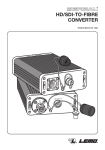
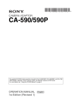
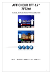
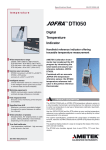
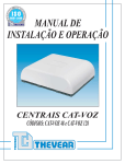
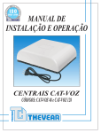
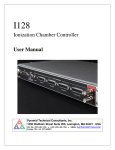
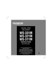
FULLY DIGITAL HD TRIAX-TO-FIBRE
VIDEO MEDIA CONVERTER
Instructions for use
In
12V DC
12V DC In
On/Off
12V DC In
On/Off
A
MEERKAT TM (A)
3
1
2
7
12V DC In
On/Off
B
MEERKAT TM (B)
PHW.MT.3KC.TPVP10 / S
00010 / Preserie / 1007
3
Optics
5
Triax
Fuse
2
Power
BACK PANEL
MEERKAT TM (A)
MEERKAT TM (B)
1
6
8
4
2
www.lemo.com
FULLY DIGITAL HD TRIAX-TO-FIBRE
VIDEO MEDIA CONVERTER
Instructions for use
Table of contents ▶
Presentation & Warning
Page 5
Operating Instructions
Page 6
List of compatible cameras
Page 7
Part Number & Troubleshooting
Page 8
Certifications & Warranty
Page 9
◀ Getting to know the MEERKAT TM (see page 2)
1 On/Off power switch
2 Power socket
3 HDTV connector (ARIB, SMPTE, EBU compatible)
4 Triax connector
5 Fuse
6 LED indicators
7 Part number and model
8 Triax cable
www.lemo.com
3
A compact solution for Sony ® and Thomson ®
(Grass Valley ™) HD camera based systems
The LEMO MEERKAT TM HD Triax media
converter system is a compact “plug and
play” transmission system that provides a
fibre link between HD Triax cameras and
and their CCU’s. The LEMO Media Converter offers mobile facility providers,
production centres and broadcast
studios an appropriate and professional
solution for long distance signal transmission.
fibre. The SMPTE 311M hybrid cable
uses the well proven technology of the
LEMO 3K.93C series HDTV connector.
If power from the CCU / OB van is not
required (i.e. local power is available), a
two fibre cable using 2 x FC-PC or 2 x SC
may be used for signal transmission.
Going the distance digitally
Get more from your cables
HD TRIAX
The camera is powered via a hybrid cable
from the CCU with both the camera signals and the return monitor signals being
digitally encoded and transmitted over
SD TRIAX
2 km
Fibre (with remote power)
2 km
up to 1 km
Fibre (with local power)
up to 20 km
Before operating the system please read the User Manual.
Warning
To prevent fire or shock hazard, do not
immerse the unit in water.
To avoid electrical shock, do not remove covers or panels.
To prevent overheating risk, ventilate
the units correctly.
CAUTION
RISK OF ELECTRIC SHOCK
DO NOT OPEN
Only use the power supply included.
CAUTION TO REDUCE THE RISK OF ELECTRIC SHOCK,
Refer servicing to qualified personnel
only.
DO NOT REMOVE COVER (OR BACK).
NO USER-SERVICEABLE PARTS INSIDE.
REFER SERVICING TO QUALIFIED SERVICE PERSONNEL.
Use only fuses of the type and rating
specified.
4
www.lemo.com
List of HD compatible cameras
Camera
Recommended variants
of SMPTE-311M Cable
Part Nr
Type
Triax Camera
Adaptor
Part Nr
Part Nr
Type
THOMSON ®
LDK 3000
HD
LDK5630
LDK4580
HD
THOMSON ®
LDK 4000
HD
Manufacturer
Base Station
LDK5460
LDK4502
LDK5860
LDK4506
HD
THOMSON ®
LDK 6000
HD
LDK5460
LDK4502
HD
THOMSON ®
LDK 6200
HD
LDK5462
LDK4506
HD
THOMSON ®
LDK 8000
HD
LDK5860
LDK4502
HD
THOMSON
LDK 8000
(sport)
®
HD
LDK5860
LDK4506
HD
Notes : Do not connect any camera other than those
on the list above without contacting the LEMO Technical
Support Group.
Manufacturer
2SM-9.2-37.5
Furukawa
TV-OM-AMS
Furukawa
TV-OM-HAMS
Fujikura
B-97J501
Draka
CT2987300
Belden
7804C
Mohawk
M96040
Mohawk
M95421
Specifications
List of SD compatible cameras
Camera
Part Number (camera cable)
Furukawa
Input/outputs
I/O ports
DC in
LEMO 0K Series, 2pin
in-line transformer
Type
Triax Camera
Adaptor
Part Nr
Part Nr
Type
SONY ®
BVP-E30
SD
CA590
CCU-790
SD
SONY ®
BVP550
SD
CA550
CU-550
SD
SONY
®
BVP950
SD
CA570
CCU-700
SD
Dimensions
125W x 270L x 50H mm
SONY ®
BVP700
SD
CCU-700
Mass (approx.)
2 Kg
SONY ®
BVP750
SD
CCU-700
Power requirements
In North America,
Japan and areas
of South America
100 to 120 Vac, 50/60Hz
Power requirements
In Europe, Africa,
Australia, Scandinavia,
China
220 to 240 Vac, 50/60 Hz
Power consumption
16 W
Operating voltage
12 Vdc / 1.5A max
Operating temperature
-20°C to +55°C
Humidity
up to +95%
Index protection
IP66 (when mated)
Manufacturer
Part Nr
Base Station
Connectors
Triaxial connector 50 Ohms / 75 Ohms
LEMO 3K.93C Series, (HDTV)
SONY ®
CCU-750
SONY ®
CCU-500
LDK5400
THOMSON ®
LDK20s
LDK4053
SD
LDK100
SD
LDK5430
LDK4501
LDK5400
LDK4053
LDK5430
LDK5401
SD
THOMSON ®
LDK200
SD
LDK5400
THOMSON ®
LDK300
SD
SD
LDK5430
LDK4501SL
LDK5400
THOMSON ®
LDK400
SD
SD
LDK5430
LDK4501SL
General
Signals
LDK5400
THOMSON ®
LDK500
SD
Values
SD
LDK5430
LDK4501SL
Notes : Do not connect any camera other than those
on the list above without contacting the LEMO Technical
Support Group.
Optical RX sensitivity
-3dB to -21dB
Data rate
2x2.5 GB/s
Optical Tx output
200µW (250µW max)
Transm. wavelength
1310nm /1550nm
Supplied accessories
Fuse
AC/DC power supply
User's guide
www.lemo.com
Values
Quantity
4 X 4 Amp Wickmann TR5
2
with UK, USA, Europe adaptors
1
5
Operating Instructions - Remote Camera Power
Remote Camera Power
(SMPTE 311M cable)
MEERKAT™ (A)
1m - TRIAX
Local 12 V source (1.5 A max)
MEERKAT™ (B)
2 km - SMPTE 311M cable
1m - TRIAX
12 V - 1.5 A max
Option 1 - Remote Camera Power
MEERKAT Power Supply.
With the Remote Camera Power setup, the camera
is powered directly through the SMPTE-311M
cable. The useable cable length of the SMPTE 311M cables is limited by the resistance of the
copper power conductors and will vary between
cables from different cable manufacturers. However
distances of up to 2 km are achievable.
Connect the unit to a suitable power source by
using either the AC/DC adaptor (12Volts) supplied
or the battery belt / power pack that is available as
an optional accessory (common battery pack manufacturers).
Triax connector.
Connect the Triax connector (provided with 1 metre
cable lead) to the appropriate socket located on the
Triax camera or the OB van. Connect Unit A to the
camera and Unit B to the OB van/CCU.
On/Off power switch
Press the power button to turn the power on, the
power LED will illuminate. The camera picture
should stabilise and all the green LEDs should be
illuminated, if not see chapter on troubleshooting
(page 8). Pressing the power button again will turn
the power off.
HDTV connectors.
Connect the HDTV connector (LEMO 3K.93C
Series) to the appropriate HDTV compatible socket
or plug. Note: as with HDTV systems ensure that
the HDTV (SMPTE) cable is laid in the appropriate
direction - socket at the OB van / CCU end and plug
at camera end.
6
www.lemo.com
Operating Instructions - Local Camera Power
Local Camera Power
(2 x SC or 2 x FC/PC optic cable)
MEERKAT™ (A)
1m - TRIAX
Local power
≥ 20 km - 2 x SC
or 2 x FC/PC optic cable
Maximum transmission distance
determined by the camera system
power budget
Local 12 V source (1.5 A max)
MEERKAT™ (B)
1m - COAX/TRIAX
12 V - 1.5 A max
Option 2 - Local Camera Power
MEERKAT Power Supply.
With the Local Camera Power setup, the camera is
powered with its AC or DC voltage from a local
source of power either - a generator or a power
pack.
Connect the unit to a suitable power source by
using either the AC/DC adaptor (12Volts) supplied
or the battery belt / battery pack that is available as
an optional accessory (common battery pack manufacturers).
Triax connector.
Connect the Triax connector (provided with 1 metre
cable lead) to the appropriate socket located on the
Triax camera or the OB van. Connect Unit A to the
camera and Unit B to the OB van/CCU.
HDTV connectors.
Connect the HDTV connector (LEMO 3K.93C
Series) to the appropriate HDTV compatible socket
or plug. Connect the two SC, or FC-PC connectors
to the corresponding connectors on your dual
channel fibre cable. Note that two cable adaptors
(hybrid connector to 2x SC/FC-PC connectors) will
be required.
www.lemo.com
On/Off power switch
Press the power button to turn the power on, the
power LED will illuminate. The camera picture
should stabilise and all the green LEDs should be
illuminated, if not see chapter on troubleshooting
(page 8). Pressing the power button again will turn
the power off.
7
Part Number
The device doesn’t operate.
The MEERKAT system always works as a pair.
These are identified as MEERKAT TM (A) and
MEERKAT TM (B) in the operating instructions.
Depending on the camera brand and the triaxial
connector fitted on the OB van, you will need to
select a specific part number. For other configurations that are not described in the part numbers
table here below, please contact your local LEMO
customer support.
Is the power LED lit (location at the rear of the
chassis)? If not check if the power supply is correctly
plugged in and that the on/off button is switched on.
Check the circuit protection fuse. If it has blown
replace it (see chapter fuse replacement). If this fuse
blows repeatedly, please contact technical support.
TM
/T
0/S
FVP1
KC.T / 2307
2
.MT.3
FGW / 931954
9
12V
0000
O n /O
LED
Optics
DC
in
Triax
No light
Red
Green
No data
received
Bad data
received
OK
Off
No triax signal
Triax
overdrive 1)
OK
Power off
-
Power On
ff
Power
Note : 1) Triax overdrive means that the signal experiences
clipping i.e. the triax signal amplitude is too high (seek Technical Support).
The part number of your purchased product is
located on the top of the unit (see above).
PHW.MT.3TM.TFRP10
FGG.4M.650.CTLC90Z
Plug 4M.650
PHW.MT.3TM.TPRP10
PHG.4M.650.CTAC90Z
Socket 4E.675
PHW.MT.3TM.TFUP10
FFA.4E.675.CTAC90Z
Plug 4E.675
PHW.MT.3TM.TPUP10
PCA.4E.675.CTLC90Z
Socket 4A.675
PHW.MT.3TM.TFVP10
FXB.4A.675.CTCC85Z
Plug 4A.675
PHW.MT.3TM.TPVP10
PXA.4A.675.CTRC85Z
Socket REDEL F
PHW.MT.3TM.TFWP10
REDEL FAZ.T75.FTCC86CZ
Socket 3T.675
PHW.MT.3TM.TFTP10
FFA.3T.675.CTAY92S
LEMO
triax connector
on the CCU
Part number of the
MEERKAT™ (B)
on the CCU side
Power
Socket 4M.650
Electrical triax connector
on cable
Triax
Part number of the
MEERKAT™ (A)
on the camera side
To replace the fuse, first press on the On/Off button
to turn off the unit, disconnect the power supply
and HDTV cable. Unscrew the fuse cap located at
the rear of the MEERKAT TM. Carefully remove the
fuse cap, there is a sealing o-ring located inside the
fuse cap. Replace the blown fuse with a new one
that is provided in the case. Screw the fuse cap
back onto the unit.
Optics
LEMO
triax connector
on the camera
Fuse replacement
Fuse
Electrical triax connector
on cable
Plug 4M.650
FGW.MT.3TM.TPRP10
PHG.4M.650.CTAC90Z
Socket 4M.650
FGW.MT.3TM.TFRP10
FGG.4M.650.CTLC90Z
Plug 4E.675
FGW.MT.3TM.TPUP10
PCA.4E.675.CTLC90Z
Socket 4E.675
FGW.MT.3TM.TFUP10
FFA.4E.675.CTAC90Z
Plug 4A.675
FGW.MT.3TM.TPVP10
PXA.4A.675.CTRC85Z
Socket 4A.675
FGW.MT.3TM.TFVP10
FXB.4A.675.CTCC85Z
Plug REDEL F
FGW.MT.3TM.TPWP10
REDEL FRZ.T75.FTMC86CZ
Plug 3T.675
FGW.MT.3TM.TPTP10
PCA.3T.675.CTLY92S
Note : the units are not provided with the SMPTE 311M
cables. Part number above are for Thomson HD camera.
The device gets warm.
This is normal; the units get warm during normal
operation. The shell heat exchanger should be kept
free of obstructing materials and not covered, in
order to dissipate the heat.
Troubleshooting
Why doesn’t it work the way I want?
This section lists some problems you might encounter during the use of the MEERKAT TM . Some
problems require that you call your local support,
but other problems can easily be solved.
8
www.lemo.com
Certifications and warranty
CAUTION Class 1 Laser Product
CE marking
The MEERKAT TM is classified as a CLASS 1 LASER
PRODUCT. Do not stare into the beam or view it
directly with optical instruments.
CE marking means that the appliance or equipment
bearing it complies with the protection requirements
of one or several European safety directives.
FCC Compliance Statement
This device complies with Part 15 of the FCC Rules.
Operation is subject to the following two conditions:
1. This device may not cause harmful interference.
2. This device must accept any interference
received, including interference that may cause
undesired operation.
Note: This equipment has been tested and found
to comply with the limits for a Class B digital device,
pursuant to Part 15 of the FCC Rules.
These limits are designed to provide reasonable
protection against harmful interference in a
residential installation.
This equipment generates, uses and can radiate
radio frequency energy and, if not installed and used
in accordance with the instructions, may cause
harmful interference to radio communications.
However, there is no guarantee that interference will
not occur in a particular installation. If this equipment
does cause harmful interference to radio or
television reception, which can be determined by
turning the equipment off and on, the user is
encouraged to try to correct the interference by one
or more of the following measures:
• Reorient or relocate the receiving antenna.
• Increase the separation between the
equipment and receiver.
• Connect the equipment into an outlet on a
circuit different from that to which the receiver
is connected.
• Consult the dealer or an experienced
radio/television technician for help.
RoHS statement
LEMO products are in compliance with the RoHS
directives (2002/95/EC) of the European Parliament.
This directive specifies the restrictions of the use of
hazardous substances in electrical and electronic
equipment marketed in Europe.
LEMO guarantees that its connectors and media
converters are free of mercury, cadmium, lead,
hexavalent chromium and polybromide biphenyl
(PBB) or polybromide diphenyl ether (PBDE).
Recommendations
Do not paint your product. Always treat your
product with care and keep the fibre optic
connectors capped when not in use.
Cleaning Instructions
It is essential that the optical interface (ferrule end
faces) of the 3K.93C fibre optic contacts are clean
and free from any kind of debris to ensure the
correct performance and operation of the contact. It
is recommended that the inspection and cleaning
instructions provided by LEMO are used on the
3K.93C connector to ensure the connector
performs to the specified ratings.
Technical support
We understand you may have questions regarding
your new product. Should you require any
assistance, our technical support and customer
service is available to you. Whenever calling your
LEMO support, you will need to refer to the part
numbers located on the top the MEERKAT TM unit.
Europe email: [email protected]
Europe telephone: 0044 (0) 1903 222411
USA email: [email protected]
USA telephone: (+1 707) 578 88 11
Asia/Pacific email: [email protected]
Japan telephone: +81-3-5446-5510
China telephone: (86 21) 5899 7721
Warranty - 1 year
LEMO warrants this product to be free from defects
in design, material and workmanship under normal
use for the period of one (1) year from purchase
date.
If during the warranty period, this product should fail
under normal operation, LEMO will, at its option,
replace or repair the defective part.
This warranty does not include failure caused by
improper installation, operation, accident, improper
connection to peripherals, software or hardware
modifications outside of LEMO’s control.
Design and specifications are subject to change without notice.
www.lemo.com
9
10
www.lemo.com
www.lemo.com
11
LEMO HEADQUARTERS
SWITZERLAND
LEMO SA
Chemin des Champs-Courbes 28
P.O. Box 194 - CH-1024 Ecublens
Tel. (+41 21) 695 16 00 - Fax (+41 21) 695 16 02
e-mail: [email protected]
SUBSIDIAIRIES
AUSTRIA
LEMO Elektronik
GesmbH
Tel: (+43 1) 914 23 20 0
CANADA
LEMO CANADA Inc
Tel: (+1 905) 477 77 22
CHINA
LEMO Trading
(Shanghai) Co., Ltd.
Tel: (+86 21) 5899 7721
JAPAN
LEMO Japan Ltd
Tel: (+81 3) 54 46 55 10
NETHERLANDS /
BELGIUM
LEMO Connectors
Nederland B.V.
Tel: (+31) 251 25 78 20
NORWAY / ICELAND
LEMO Norway A/S
Tel: (+47) 22 91 70 40
DENMARK
LEMO Denmark A/S
Tel: (+45) 45 20 44 00
SINGAPORE
LEMO Asia Pte Ltd
Tel: (+65) 6476 0672
FRANCE
LEMO France Sàrl
Tel: (+33 1) 60 94 60 94
SPAIN / PORTUGAL
IBERLEMO S.A.
Tel: (+34 93) 860 44 20
GERMANY
LEMO Elektronik GmbH
Tel: (+49 89) 42 77 03
SWEDEN / FINLAND
LEMO Nordic AB
Tel: (+46 8) 635 60 60
HONG KONG
LEMO Hong Kong Ltd.
Tel: (+852) 21 74 04 68
SWITZERLAND
LEMO Verkauf AG
Tel: (+41 41) 790 49 40
HUNGARY
REDEL Elektronika Kft
Tel: (+36 1) 421 47 10
UNITED KINGDOM
LEMO UK Ltd
Tel: (+44 1903) 23 45 43
ITALY
LEMO Italia srl
Tel: (+39 02) 66 71 10 46
USA
LEMO USA Inc
Tel: (+1 707) 578 88 11
LEMO
© DOC.MT.3KC.000 - Printed in Switzerland, November 2012
LEMO
DISTRIBUTORS
AUSTRALIA, BRAZIL, CZECH REPUBLIC, GREECE,
INDIA, ISRAEL, NEW ZEALAND, PAKISTAN,
POLAND, RUSSIA, SOUTH AFRICA,
SOUTH KOREA, TAIWAN, TURKEY, UKRAINE
www.lemo.com
12
www.lemo.com