1
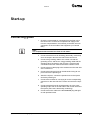
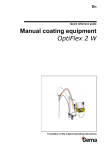
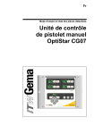
En Quick reference guide OptiFlex F Manual coating equipment Translation of the original operating instructions V 04/13 Quick reference guide OptiFlex F manual coating equipment © Copyright 2006 Gema Switzerland GmbH All rights reserved. This publication is protected by copyright. Unauthorized copying is prohibited by law. No part of this publication may be reproduced, photocopied, translated, stored on a retrieval system or transmitted in any form or by any means for any purpose, neither as a whole nor partially, without the express written consent of Gema Switzerland GmbH. OptiTronic, OptiGun, EasyTronic, EasySelect, OptiFlow and SuperCorona are registered trademarks of Gema Switzerland GmbH. OptiMatic, OptiMove, OptiMaster, OptiPlus, MultiTronic and Gematic are trademarks of Gema Switzerland GmbH. All other product names are trademarks or registered trademarks of their respective holders. Reference is made in this manual to different trademarks or registered trademarks. Such references do not mean that the manufacturers concerned approve of or are bound in any form by this manual. We have endeavored to retain the preferred spelling of the trademarks, and registered trademarks of the copyright holders. To the best of our knowledge and belief, the information contained in this publication was correct and valid on the date of issue. Gema Switzerland GmbH makes no representations or warranties with respect to the contents or use of this publication and reserves the right to revise this publication and make changes to its content without prior notice. Printed in Switzerland Gema Switzerland GmbH Mövenstrasse 17 9015 St. Gallen Switzerland Phone: +41-71-313 83 00 Fax.: +41-71-313 83 83 E-Mail: [email protected] Homepage: www.gemapowdercoating.com V 04/13 Table of contents General safety regulations 3 OptiFlex F 9 Technical data ....................................................................................................... 10 Start-up ................................................................................................................. 11 Maintenance and cleaning .................................................................................... 13 Spare parts list OptiFlex F .................................................................................... 15 OptiStar CG07 21 Technical Data ...................................................................................................... 22 Start-up and operation .......................................................................................... 23 Spare parts list OptiStar CG07 ............................................................................. 34 OptiSelect Manual powder gun 41 Technical Data ...................................................................................................... 42 Start-up and operation .......................................................................................... 43 Maintenance and cleaning .................................................................................... 46 Troubleshooting guide .......................................................................................... 48 Spare parts list OptiSelect .................................................................................... 50 OptiFlow (IG02 type) 61 Cleaning and maintenance ................................................................................... 64 Troubleshooting guide .......................................................................................... 66 Spare parts list OptiFlow ....................................................................................... 67 OptiFlex F manual coating equipment Table of contents • 1 V 04/13 General safety regulations Safety symbols (pictograms) The following warnings with their meanings can be found in the Gema operating instructions. The general safety precautions must also be followed as well as the regulations in the operating instructions. DANGER! Danger due to live electricity or moving parts Possible consequences: Death or serious injury ATTENTION! Improper use of the equipment could damage the machine or cause it to malfunction. Possible consequences: Minor injuries or damage to equipment NOTE! Useful tips and other information OptiFlex F manual coating equipment General safety regulations • 3 V 04/13 The OptiFlex manual coating equipment is built to the latest specification and conforms to the recognized technical safety regulations and it is designed for the normal application of powder coating. General information Any other use is considered as non-conform. The manufacturer is not responsible for any damage resulting from this - the risk for this is assumed by the user alone! If the OptiFlex manual coating equipment is to be used for other purposes or other substances outside of our guidelines, then Gema Switzerland GmbH should be consulted. Observance of the operating, service and maintenance instructions specified by the manufacturer is also part of conformity of use. The relevant accident prevention regulations, as well as other generally recognized safety regulations, occupational health and structural regulations are to be observed. Furthermore, the country-specific safety regulations also must be observed. Further safety and operation notices will be found on the accompanying CD or on the homepage www.gemapowdercoating.com. The start-up is forbidden until it has been established that the manual coating equipment has been set up and wired according to the EU guidelines for machinery. Unauthorized modifications to the manual coating equipment exempt the manufacturer from any liability from resulting damages or accidents. General danger The operator must ensure that all users do have the appropriate training for powder spraying equipment and are aware of the possible sources of danger. Any operating method, which will negatively influence the technical safety of the powder spraying equipment, is to be avoided. For your own safety, only use accessories and attachments listed in the operating instructions. The use of other parts can lead to risk of injury. Only original Gema spare parts should be used! Repairs must only be carried out by specialists or by authorized Gema service centers. Unauthorized conversions and modifications can lead to injuries and damage to the equipment, and the Gema Switzerland GmbH guarantee would no longer be valid. These general safety regulations must be read and understood mandatory before start-up! 4 • General safety regulations OptiFlex F manual coating equipment V 04/13 The connecting cables between the control unit and the spray gun must be installed in such a way, that they cannot be damaged during the operation. Please observe the local safety regulations! The plug connections between the powder spraying equipment and the mains should only be removed when the power supply is switched off. Electrical danger All maintenance activities must take place when the powder spraying equipment is switched off. The powder coating equipment may be able to be switched on only if the booth is in operation. If the booth stops, the powder coating device must switch off too. The control units for the spray guns must be installed and used in zone 22. Spray guns are allowed in zone 21. Only original Gema spare parts will guarantee that the explosion protection will be preserved. If damages occur by using spare parts from other manufacturers, the warranty or compensation claim is void! Conditions leading to dangerous levels of dust concentration in the powder spraying booths or in the powder spraying areas must be avoided. There must be sufficient technical ventilation available, to prevent a dust concentration of more than 50% of the lower explosion limit (UEG = max. permissible powder/air concentration). If the UEG is not known, then a value of 10 g/m³ should be considered (see EN 50177). Explosion hazard All unauthorized conversions and modifications to the electrostatic spraying equipment are forbidden for safety reasons. No safety devices should be dismantled or put out of operation. The operating and job instructions has to be written in an understandable form and in the language of the persons employed, and has to be announced in a suitable place in the working area. Powder lying on the floor around the powder spraying equipment is a potentially dangerous source of slipping. Booths may be entered only in the places suitable for it. Slip hazard OptiFlex F manual coating equipment General safety regulations • 5 V 04/13 Static charges Static charges can have the following consequences: Charges to people, electric shocks, sparking. Charging of objects must be avoided by a proper grounding. Grounding All electricity conducting parts found in the workplace of 5 meters around each booth opening, and particularly the objects to be coated, have to be grounded. The earthing resistance of each object must amount to maximally 1 MOhm. This resistance must be checked/tested regularly when starting work. Observe the grounding regulations The condition of the work piece attachments, as well as the hangers, must guarantee that the work pieces remain grounded. The appropriate measuring devices must be kept ready in the workplace, in order to check the grounding. The floor of the coating area must conduct electricity (normal concrete is generally conductive). The supplied grounding cable (green/yellow) must be connected to the grounding screw of the electrostatic manual powder coating equipment. The grounding cable must have a good metallic connection with the coating booth, the recovery unit and the conveyor chain, respectively with the suspension arrangement of the objects. Smoking and igniting fire are forbidden in the entire plant area! All sparkgenerating works are forbidden! Fire and smoke prohibition The stay for persons with cardiac pacemakers is forbidden 6 • General safety regulations As a general rule for all powder spraying installations, persons with pacemakers should never enter high voltage areas or areas with electromagnetic fields. Persons with pacemakers should not enter areas with powder spraying installations! OptiFlex F manual coating equipment V 04/13 Photographing with flashlight can lead to unnecessary releases and/or disconnections by safety devices. Photographing with flashlight is forbidden Disconnect the plugs before the machines are opened for maintenance or repair. Disconnect from mains before maintenance works take place The plug connections between the powder spraying equipment and the mains should only be removed when the power supply is switched off. As far as it is necessary, the operating firm must ensure that the operating personnel wear protective clothing (e.g. facemasks). The operating personnel must wear electrically conductive footwear (e.g. leather soles). The operating personnel should hold the gun with bare hands. If gloves are worn, these must also conduct electricity. These general safety regulations must be read and understood mandatory before start-up! OptiFlex F manual coating equipment General safety regulations • 7 V 04/13 OptiFlex F Scope of delivery 1 2 4 3 5 OptiFlex F manual coating equipment - structure OptiFlex F manual coating equipment - A OptiStar control unit (1) in a metal case with power supply cable - A mobile trolley with a gun/hose support (4) - A fluidized powder hopper (5) - A plug-in OptiFlow Injector (3) - An OptiSelect manual powder gun (2) with gun cable, powder hose, rinsing air hose and standard nozzle set (see therefore the OptiSelect manual powder gun user manual) - Pneumatic hoses for conveying air (red), supplementary air (black) and fluidizing air (black) OptiFlex F • 9 V 04/13 Technical data OptiFlex F manual coating equipment Electrical data OptiFlex F manual coating equipment 230-240 VAC (110-120 VAC) Nominal input voltage Frequency 50/60 Hz Input value 150 VA Pneumatical data OptiFlex F manual coating equipment Max. compressed air consumption 11 m³/h Dimensions OptiFlex F manual coating equipment 10 • Technical data Width 690 mm Depth 800 mm Height 1135 mm Weight 49 kg OptiFlex F manual coating equipment V 04/13 Start-up Connecting guide 1. Check the compressed air connection from the filter unit to the control unit. Connect the compressed air supply hose from the compressed air circuit directly to the filter unit main connection on the rear side of the equipment (1/4" female BSP) Note: The compressed air must be free from oil and water! 2. Connect the black hose for fluidizing (electrically conductive) air to the output 1.5 on the rear side of the control unit 3. Connect the grounding cable to the control unit with the grounding screw, and the 5 m long grounding cable with the clamping clip to the booth or the conveyor. Check ground connections with Ohm meter and ensure 1 MOhm or less 4. Connect the gun cable plug to the socket 2.3 on the rear side of the control unit 5. Connect the rinsing air hose to the electrode rinsing air output 1.4 and to the powder gun 6. Attach the injector, connect the powder hose to the injector and to the powder gun 7. Connect the red hose for conveying air to the corresponding output 1.2 on the rear side of the control unit and to the injector 8. Connect the black hose for supplementary air to the corresponding output 1.3 on the rear side of the control unit and to the injector (this hose is electrically conducting) 9. Connect the mains cable to the 2.1 Power IN plug and tighten with provided screw OptiFlex F manual coating equipment Start-up • 11 V 04/13 Gun Air supply IN Filter unit Power IN Aux Gun 2.1 2.2 2.3 6 - 10 bar 87 - 145 PSI 1.5 1.4 1.3 1.2 Fluidizing air Injector Connecting guide - overview Note: The further start-up procedure for the OptiFlex F manual coating equipment gun is explicitly described in the OptiStar CG07control unit operating instructions (chapter "Initial start-up" and "Daily start-up")! 12 • Start-up OptiFlex F manual coating equipment V 04/13 Maintenance and cleaning Note: Regular and conscientious maintenance increases the life span of the manual coating equipment and provides for a longer continuous coating quality! Daily maintenance 1. Clean the injector (see the OptiFlow user manual) 2. Clean the powder gun (see the OptiSelect user manual) 3. Clean the powder hose Weekly maintenance 1. Clean the powder hopper, the injector and the powder gun 2. Check the control unit grounding connections to the coating booth, the suspension devices of the work pieces, or the conveyor chain If in disuse for several days 1. Disconnect the mains plug 2. Clean the coating equipment 3. Turn off the compressed air main supply Powder hose rinsing If lengthy downtimes take place, the powder hose must be cleaned. Procedure: 1. Strip the powder hose from the hose connection on the injector 2. Point the gun into the booth 3. Blow through the hose manually with a compressed air gun 4. Fit the powder hose again to the hose connection on the injector OptiFlex F manual coating equipment Maintenance and cleaning • 13 V 04/13 14 • Maintenance and cleaning OptiFlex F manual coating equipment V 04/13 Spare parts list OptiFlex F Ordering spare parts When ordering spare parts for powder coating equipment, please indicate the following specifications: - Type and serial number of your powder coating equipment - Order number, quantity and description of each spare part - Type OptiFlex F manual coating equipment, Serial no. 1234 5678 - Order no. 203 386, 1 piece, Clamp - Ø 18/15 mm Example: When ordering cable or hose material, the required length must also be given. The spare part numbers of this yard/meter ware is always marked with an *. The wear parts are always marked with a #. All dimensions of plastic hoses are specified with the external and internal diameter: Example: Ø 8/6 mm, 8 mm outside diameter (o/d) / 6 mm inside diameter (i/d) WARNING! Only original Gema spare parts should be used, because the explosion protection will also be preserved that way. The use of spare parts from other manufacturers will invalidate the Gema guarantee conditions! OptiFlex F manual coating equipment Spare parts list OptiFlex F • 15 V 04/13 OptiFlex F manual coating equipment - spare parts list 1 Bearing bolt 1000 453 2 Countersunk Allen screw - M6x20 mm 1002 992 3 Countersunk Allen screw - M6x40 mm 1002 953 4 Handle bar 1002 623 5 Counter washer 1000 944 6 Rubber wheel - Ø 200 mm 260 592 7 Swivel wheel - Ø 50 mm 260 606 8 Rubber buffer - Ø 35x40 mm, M8/a 211 664 9 Grounding cable - complete 301 140 10 Countersunk Allen screw - M6x30 mm 1002 952 11 Hexagon shakeproof nut - M6 12 Gun holder 13 CG07 gun control unit - complete (see corresponding operating manual) 14 Plastic hose - Ø 8/6 mm, black 103 756* 15 Hose holder 1000 699 16 Filter unit - complete (see corresponding spare parts list) 17 Powder hopper HF03-50-2, without injector (see corresponding spare parts list) 18 Hexagon ribbed cylinder screw - M10x20 mm 260 584 19 Snap ring - A-25 237 094 20 Hexagon ribbed cylinder screw - M8x16 mm 261 793 21 OptiFlow IG02-V injector - complete (see corresponding user manual) 22 Spare parts set - MF02, consisting of: 244 430 1003 076 1002 016 Insert sleeve PTFE 377 724 Injector plug gauge 393 380 O-ring - Ø 16x2 mm 231 517 Fuse - 4 AT 262 897 Fuse - 2 AT 221 872 Fuse - 0.1 AT 229 520 Cable tie - L=100x2.5 mm 200 719 23 Short instruction sheet OptiStar CG07 1002 060 24 Program table sheet OptiStar CG07 1002 063 * Please indicate length 16 • Spare parts list OptiFlex F OptiFlex F manual coating equipment V 04/13 OptiFlex F manual coating equipment - spare parts 13 4 23 12 22 2 24 3 15 16 14 11 21 10 17 8 20 9 5 1 6 19 7 18 OptiFlex F manual coating equipment - spare parts OptiFlex F manual coating equipment Spare parts list OptiFlex F • 17 V 04/13 OptiFlex F manual coating equipment - powder hopper A Powder hopper - complete 1001 655 B Hopper body - complete (pos. 1-9) 1001 644 1 Floor plate 1001 640 2 Fluidizing plate 390 151 3 Fluidizing bed seal 390 186 4 Clamp ring 390 194 5 Sealing ring - Ø 10.2/17x3.8 mm 230 626 6 Elbow screw connection - 1/8"a-1/8"a 7 Bezel - Ø 1.4 mm 371 912 8 Connector - NW5, 1/8"i 200 859 9 Protective strip 103 837 10 1001 079 Hopper cover - complete 1001 648 Spiral hose - Ø 40/45 mm, for pos. C (not shown) 100 048* 13 Blind grommet - Ø 36x12 mm 238 333 14 Suction tube - complete, L=504 mm (incl. pos. 15) 339 130 15 O-Ring - Ø 28.3x1.78 mm 224 987 16 Lock nut - PG21 234 869 C 1002 043 Airmover - complete (incl. pos. 17-23) 17 Venting tube 375 845 18 O-Ring - Ø 38x4 mm 239 151 19 Locknut 342 343 20 Double nipple - 1/8"a-1/8"a 202 258 21 Ball valve 260 967 22 Throttle valve - 1/8"a-1/8"a 23 Connector - NW5-1/8"a D 1002 127 237 272 Pneumatic connection fluidizing air - complete (not shown), consisting of: Quick release connection - NW5, Ø 6 mm 200 840 Plastic hose - Ø 6/4 mm, black 1001 973* Nut with kink protection - M10x1 mm, Ø 6 mm E 1002 042 201 308 Pneumatic connection Airmover - complete (not shown), consisting of: 1002 058 Plastic hose - Ø 8/6 mm, black 103 756* Quick release connection - NW5, Ø 8 mm 203 181 * Please indicate length 18 • Spare parts list OptiFlex F OptiFlex F manual coating equipment V 04/13 OptiFlex F manual coating equipment - powder hopper E 17 18 19 13 23 10 22 21 20 9 16 15 14 2 3 4 D 1 5 6 7 8 OptiFlex F manual coating equipment - powder hopper OptiFlex F manual coating equipment Spare parts list OptiFlex F • 19 V 04/13 OptiFlex F - filter unit Filter unit - complete, without pos. 14 1001 147 1 Filter separator - MAF200L-8A 1007 321 2 T-piece - 1/4"i-1/4"a-1/4"i 3 Elbow joint - 1/4"-3xØ 8-8 mm 1007 327 7 Filter cartridge - 20 µm 1007 325 9 Manometer - G1/4", 0-10 bar 1007 328 10 Rectus nipple - NW 7.4-1/4"a 256 730 11 Grommet - Ø 8 mm 238 023 12 Elbow joint - 1/4"i-1/4"a 222 674 14 Rectus quick release connection (for pos. 10) - NW 7.8-Ø 10 mm 239 267 262 064 9 1 2 12 3 10 11 14 11 7 OptiFlex F - filter unit 20 • Spare parts list OptiFlex F OptiFlex F manual coating equipment V 04/13 OptiStar CG07 Operating modes The OptiStar CG07 Manual gun control unit can be operated with two operating modes. According to the selected application mode, the spray voltage and the spray current are automatically adjusted and limited. Predefined operating mode (Preset mode) The CG07 Manual gun control unit provides three predefined application modes (flat parts, complicated parts and recoat parts already painted one time). When operating in this mode, the spray voltage and spray current are automatically set and limited. In this operating mode, current (µA) and high voltage (kV) are preset, powder and air volume can be adjusted and saved. The powder and air volume are stored separately for each predefined application mode. User-defined operating mode (Program mode) In this operating mode, 20 individually definable programs (P01-P20) are available. These programs are automatically saved and can be recalled again as the application requires. The values for current, high voltage, powder output, total air, electrode rinsing air and fluidizing air (if available) can be set as needed for a given application. Note: The specified values in the 20 programs and 3 application modes are saved automatically, without confirmation, after a two second delay and the display changes from preset values to actual values! OptiFlex F manual coating equipment OptiStar CG07 • 21 V 04/13 Technical Data OptiStar CG07 Manual gun control unit Connectable guns OptiStar CG07 connectable OptiSelect GM02 yes OptiGun GA02 only with trigger adapter PG1 yes PG2-A / PG2-AX only with trigger adapter PG3-E** yes TriboJet* yes, with adapter * The gun type must be adjusted (reference chapter "Additional options"). The Tribo gun is not type approved (ATEX). ** Only for enamel powder, the gun is not type approved (ATEX). Attention: The OptiStar CG07 Manual gun control unit can only be used with the specified gun types! Electrical data OptiStar CG07 Mains input voltage 100-240 VAC Operating frequency 50-60 Hz Input power (without vibrator) 40 VA Nominal output voltage (to the gun) max. 12 V Nominal output current (to the gun) max. 1 A Vibrator connection and power (on the Aux output) Protection type Temperature range Max. operating temperature Approvals 22 • Technical Data 110/220 VAC max. 100W IP54 0°C - +40°C (+32°F - +104°F) 85°C (+185°F) II (2) 3 D PTB05 ATEX 5009 OptiFlex F manual coating equipment V 04/13 Start-up and operation Connections OptiStar CG07 Manual gun control unit - connections on the rear wall Connection Description 1.1 Air Supply IN Compressed air connection (6-10 bar / 87-145 PSI) 2.1 Power IN Mains cable connection (100-240 VAC) 2.2 Aux Vibration motor connection for OptiFlex B 2.3 Gun Gun cable connection 1.5 Fluidizing air connection 1.4 Electrode rinsing air connection 1.3 Supplementary air connection 1.2 Conveying air connection Grounding connection OptiFlex F manual coating equipment Start-up and operation • 23 V 04/13 Connection guide 1. Check the compressed air connection from filter unit to control unit. Connect the compressed air supply hose from the compressed air circuit directly to the filter unit main connection on the rear side of the equipment (1/4" female BSP) Note: The compressed air must be free from oil and water! 2. Connect the black hose for fluidizing air (electrically conductive) to the output 1.5 on the rear side of the control unit 3. Connect the grounding cable to the control unit with the grounding screw, and the 5 m long grounding cable with the clamping clip to the booth or the conveyor. Check ground connections with Ohm meter and ensure 1 MOhm or less 4. Connect the gun cable plug to the socket 2.3 on the rear side of the control unit 5. Connect the rinsing air hose to the electrode rinsing air output 1.4 and to the powder gun 6. Insert the injector, connect the powder hose to the injector and to the powder gun 7. Connect the red hose for conveying air to the corresponding output 1.2 on the rear side of the control unit and to the injector 8. Connect the black hose for supplementary air to the corresponding output 1.3 on the rear side of the control unit and to the injector (this hose is electrically conducting) 9. Connect the mains cable to the 2.1 Power IN plug and tighten with provided screw Note: If no vibration motor (OptiFlex B) is connected, the 2.2 Aux output is to be locked tightly with the provided protection cap! 24 • Start-up and operation OptiFlex F manual coating equipment V 04/13 Powder gun Air supply IN Filter unit Power IN Aux Gun 2.1 2.2 2.3 6 - 10 bar 87 - 145 PSI 1.5 1.4 1.3 1.2 Fluidizing air Injector Connecting guide - overview Pin assignment Power IN connection 2 3 PE 1 1 Neutral conductor (power supply) 2 Phase conductor (100-240 VAC) 3 PE Stirrer output Ground PE Aux connection 2 1 3 1 Vibrator phase output 2 Neutral conductor 3 PE PE Not used Ground PE Gun connection 4 5 3 PE 6 2 1 1 Ground 2 Remote control 1 (GM02) 3 Chassis ground 4 Trigger 5 Remote control 2 (GM02) 6 Oscillator PE OptiFlex F manual coating equipment Ground PE Start-up and operation • 25 V 04/13 Initial start-up Setting the device type Adjust the corresponding device type (fluidizing, box or stirrer device) by pressing the key T16. Note: If the control unit is supplied as a component of an OptiFlex complete unit, then the corresponding system parameter is set correctly by the factory! Manual devices are subdivided into fluidizing, box or stirrer types. These types differ in the control of the vibrator output and the behavior of the fluidizing air. Device type AUX output function Fluidizing air function Fluidizing device (OptiFlex F) Always Off (no vibration) Fluidizing air is controlled by two different methods: Turning on the fluidization key T16 will feed air to the hopper until key is turned off Triggering the gun is turning on the fluidization too, fluidization can be turned off with key T16 Vibration On during triggering, delay of 1 minute after releasing gun trigger Fluidizing air is switched On parallel by the trigger. It runs after for 1 minute The key T16 switches the vibration On and Off The key T16 switches the fluidization On and Off parallel to the vibration Stirrer device (OptiFlex S) Stirrer On when gun triggered No fluidization, no function of key T16 Manual unit with fluidization (OptiFlex S Fd) Stirrer On when gun triggered Fluidization is switched On and Off with trigger Box device (OptiFlex B) The key T16 switches Off the fluidization, it can only be turned On by pressing the key again Note: The system parameter P0 of the manual unit may not be set on 3 (automatic unit)! A wrong parameterization leads to various malfunctions! Preparing the powder hopper/container Prepare the powder hopper or powder box according to manual equipment type (OptiFlex F, B, S, L etc.), reference the operating manual for the equipment type being used. 26 • Start-up and operation OptiFlex F manual coating equipment V 04/13 Switch on the booth Switch on the powder coating booth according to its operating manual. Daily start up The daily start-up of the OptiStar CG07 Manual gun control unit takes place by the following steps: Select the operating mode Select the application mode with three predefined modes (Preset mode) or the user-defined program mode with 20 user-defined programs (Program mode). 1. Turn on the gun control unit with the ON key 2. Select the corresponding application mode with key T12 (for Program mode) or keys T13/T14/T15 (for Preset mode) The predefined mode automatically set values for high voltage and spraying current: Presetting Desired µA Desired kV Flat parts 100 100 Complicated parts 22 100 Overcoating 10 100 Predefined application mode (Preset mode) Select the preset mode with the application keys T13/T14/T15. The LED of the corresponding key illuminates. No program number will be shown on the display A5. The air values can be individually specified and are automatically stored in the corresponding program. Application mode for flat parts This application mode is suitable for the coating of simple, flat workpieces without larger cavities. Application mode for complicated parts This application mode is suitable for the coating of three-dimensional workpieces with complicated shapes (e.g. profiles). Application mode for recoating parts already coated This application mode is suitable for recoating of workpieces which are already coated. Exiting the Preset mode Exit the Preset mode with the keys T10, T11 or T12. The preset values of the Program mode used before the Preset mode are displayed by the control unit memory. OptiFlex F manual coating equipment Start-up and operation • 27 V 04/13 User-defined mode (Program mode) Select this application mode with the key T12. Here, 20 user-defined programs can be set and saved. The programs 1-20 were loaded with presets by factory (4.0 Nm³/h total air, 60% powder output, 80 kV high voltage, 80 µA spray current, 0.2 Nm³/h electrode rinsing air and 1.0 Nm³/h fluidizing air). Setting powder output and powder cloud The powder output is dependent on the selected powder amount (in %) and the adjusted total air volume. Setting the total air volume 1. Adjust the total air volume with the keys T3/T4 (see also the injector operating manual) - Adjust the total air volume according to the corresponding coating requests Setting the powder output 1. Adjust the powder output volume (e.g. according to the desired coating thickness) - The selection takes place with the keys T1/T2 on the control unit or with the +/- keys on the rear side of the powder gun (OptiSelect gun type). Factory default setting of 60% is recommended for initial spraying. The total air volume is thereby kept constant automatically by the control unit 2. Check the powder fluidizing in the hopper and ensure you have a small simmer or very low boiling action 3. Point the gun into the booth, press the gun trigger and visually check the powder output Note: As a factory default value, a powder rate of 60% and a total air volume of 4 Nm³/h are recommended. By inserting values, which the equipment cannot convert, the operator is made aware by flashing of the appropriate display and a temporary out of range message! Setting the electrode rinsing air 1. Adjust the correct electrode rinsing air according to the applied nozzles (deflector plate, flat jet nozzle), see note below for default/starting values 28 • Start-up and operation - Press key T9 (SELECT) The second display level is switched over - Press keys T7/T8: Here, the corresponding air volume value is entered - If this display level is not operated for 3 seconds, the first display level is switched over independently OptiFlex F manual coating equipment V 04/13 Note: By using flat jet nozzles, the factory default value is approx. 0.2 Nm³/h, by using round jet nozzles with air-rinsed deflector plates, the factory default value is approx. 0.5 Nm³/h! Setting the fluidizing The fluidizing can be adjusted on the OptiFlex B, OptiFlex S and OptiFlex F Manual coating equipment. The powder fluidizing depends on the powder type, the air humidity and the ambient temperature. Fluidizing and vibration start by switching on the control unit. Procedure: 1. Adjust the air mover by turning the ball valve fully open and adjusting needle valve as required. The ball valve and needle valve are located on the air mover (OptiFlex F) 2. Open the powder hopper cover 3. Press key T9 (SELECT) The second display level is switched over 4. Adjust the fluidizing air with the keys T5/T6 - If the adjustment keys (+ or -) are not operated after 3 seconds, the display will go back to the µA display - The powder should "simmer" inside the hopper. Occasional mixing of the powder might be required 5. Close the cover again 6. According to the device type, stirrer, vibration and/or fluidizing can be switched on now Powder coating Attention: Make sure first, that all electrically conductive parts within 5 m of the coating booth are grounded! 1. Take the gun into the hand and hold it into the coating booth, but do not yet direct it to the object to be coated 2. Select the operating mode: Select the operating mode with program key T12 or application keys T13/T14/T15. The LED of the corresponding application key illuminates 3. Adjust powder delivery and total air settings as required. This will need to be done as the gun is triggered to visualize the spray pattern 4. Press the powder gun trigger 5. Coat the objects OptiFlex F manual coating equipment Start-up and operation • 29 V 04/13 Remote control by GM02 manual gun Various functions can be remotely controlled with the + and - keys on the back side of the powder gun (OptiSelect gun type): - Adjust the powder output by pressing the + or - key on the gun. The powder output will be increased or decreased accordingly - Change application modes (Preset mode/Program mode) by pressing the + and - keys on the gun at the same time. The change takes place counterclockwise. Check by observing the key LEDs on the control unit Note: By pressing one of the keys, the preset values display will be shown! Shut-down The shut-down of the OptiStar CG07 Manual gun control unit takes place in following steps: 1. Remove the powder gun trigger 2. Switch off the control unit 3. Switch off the Airmover (OptiFlex F) Note: The adjustments for high voltage, powder output, electrode rinsing air and fluidizing remain stored! If in disuse during several days 1. Remove the mains plug 2. Clean the coating equipment (see the corresponding operating manual) 3. Turn off the compressed air main supply Saving programs Note: The values in programs 1-20 and the 3 preset application modes are saved automatically, without confirmation! 30 • Start-up and operation OptiFlex F manual coating equipment V 04/13 Error diagnosis of the software General information The correct function of the OptiStar CG07 Manual gun control unit is constantly monitored. If the equipment software determines a fault, an error message is indicated with an error code. Following is monitored: - High voltage technology - Air technology - Power supply Help codes The error diagnosis codes (error codes) are shown in the display A5. The error codes are stored in an error list in the order of their occurrence. Each error in the list must be individually acknowledged with the keys T10 or T11. The error codes are shown with the format Hnn, whereby nn is the numeric code, if necessary with a leading zero. The errors are displayed in the order of their occurrence. The keys T10 and T11 cannot be used for other functions, as long as an error code is shown on A5. Here is the complete listing of all error codes possible for the OptiStar CG07 Manual gun control unit: Code Description Criteria Remedy Solenoid coil current lower than preset limiting value Main solenoid valve error, connection cable from main solenoid valve to basic electronics is missing, check main solenoid valve Pneumatics: H06 Trigger valve (main solenoid valve) H07 Supplementary air volume too high (total air setting on display) The preset value for supplementary air is too high compared to your conveying air setting Reduce supplementary air value or increase conveying air value to balance air volume to injector and clear help code H08 Conveying air volume too high (powder % setting on display) The preset value for conveying air is too high compared to your supplementary air setting Reduce conveying air value or increase supplementary air value to balance air volume to injector and clear help code Reduce powder output Powder output higher than 100% The powder output multiplied with the powder hose length factor and the daily correction value is larger than 100% Daily correction value too large Reduce daily correction value The theoretical value for conveying air falls below minimum Limit conveying air to conveying air minimum H09 H10 Conveying air range lower deviation OptiFlex F manual coating equipment Valve defective, main board or cable defective Total air is smaller than minimum Start-up and operation • 31 V 04/13 Code Description Criteria Remedy No oscillation, cable broken, oscillator or gun defective Replace gun cable, cascade etc. High voltage: H11 Gun error Power supply: H20 Overvoltage +15V supply Power pack defective or overloaded Replace the power pack, if error is permanent H21 Undervoltage +15V supply Power pack defective or overloaded Replace the power pack, if error is permanent H22 Undervoltage -15V supply Power pack defective or overloaded Replace the power pack, if error is permanent H23 Undervoltage +5V supply Power pack defective or overloaded Replace the power pack, if error is permanent EEPROM error Load factory settings initialize EEPROM (see therefore in chapter "RAM reset") EEPROM (equipment memory): H24 EEPROM content invalid H25 Timeout during EEPROM writing EEPROM error H26 Values not correctly stored in EEPROM during switching off EEPROM error Throttle motors: H60 Conveying air reference position not found Throttle motor or needle blocked, limit switch defective, throttle motor error Calibrate again, replace throttle valve Supplementary air reference position not found Throttle motor or needle blocked, limit switch defective, throttle motor error (see above) H61 Electrode rinsing air reference position not found Throttle motor or needle blocked, limit switch defective, throttle motor error (see above) H62 Shaping air / fluidizing air reference position not found Throttle motor or needle blocked, limit switch defective, throttle motor error (see above) H63 H64 Conveying air throttle does not move Short circuit in limit switch, throttle motor defective (see above) H65 Supplementary air throttle does not move Short circuit in limit switch, throttle motor defective (see above) H66 Electrode rinsing air throttle does not move Short circuit in limit switch, throttle motor defective (see above) H67 Shaping air / fluidizing air throttle does not move Short circuit in limit switch, throttle motor defective (see above) H68 Conveying air position lost Lost steps, limit switch defective, throttle motor defective (see above) H69 Supplementary air position lost Lost steps, limit switch defective, throttle motor defective (see above) H70 Electrode rinsing air position lost Lost steps, limit switch defective, throttle motor defective (see above) H71 Shaping air / fluidizing air position lost Lost steps, limit switch defective, throttle motor defective (see above) 32 • Start-up and operation OptiFlex F manual coating equipment V 04/13 Help codes list The last appeared four errors are stored in a list by the software. If an error appears, which is already in the list, it will not be listed again. If the list is full, no more new entries are added. Appearance of errors It is possible that an error appears just shortly, but after the acknowledgement it will disappear. In this case, switch off the OptiStar control unit and switch it on again (Reset by restarting). OptiFlex F manual coating equipment Start-up and operation • 33 V 04/13 Spare parts list OptiStar CG07 Ordering spare parts When ordering spare parts for powder coating equipment, please indicate the following specifications: - Type and serial number of your powder coating equipment - Order number, quantity and description of each spare part Example: - Type OptiFlex F manual coating equipment, Serial number 1234 5678 - Order no. 203 386, 1 piece, Clamp - Ø 18/15 mm When ordering cable or hose material, the required length must also be given. The spare part numbers of this yard/meter ware is always marked with an *. The wear parts are always marked with a #. All dimensions of plastic hoses are specified with the external and internal diameter: Example: Ø 8/6 mm, 8 mm outside diameter (o/d) / 6 mm inside diameter (i/d) WARNING! Only original Gema spare parts should be used, because the hazardous location approval will be preserved that way! The use of spare parts from other manufacturers will invalidate the Gema guarantee conditions! 34 • Spare parts list OptiStar CG07 OptiFlex F manual coating equipment V 04/13 OptiStar CG07 Manual gun control unit OptiStar CG07 Manual gun control unit - complete 1 Front plate - see corresponding spare parts list 2 Housing and power pack - see corresponding spare parts list 3 Rear wall - see corresponding spare parts list 4 Protective cover 1001 060 1004 426 3 2 1 OptiStar CG07 Manual gun control unit 4 OptiFlex F manual coating equipment Spare parts list OptiStar CG07 • 35 V 04/13 Manual gun control unit - outside rear wall OptiStar CG07 rear wall - complete (aluminum version) 1000 063 OptiStar CG07 rear wall - complete (steel version) 1004 500 Rear wall (aluminum version) 1000 067 Rear wall (steel version) 1004 175 2 OptiStar CG07 vibrator connection, assembled 1001 177 3 Milled nut - M6 4 Hose connection - complete, Ø 6/4 mm (aluminum version) 1001 520 Hose connection - complete, Ø 6/4 mm (steel version) 1004 184 Hose connection - complete, Ø 8/6 mm (aluminum version) 1001 519 Hose connection - complete, Ø 8/6 mm (steel version) 1004 183 Rectus quick release connection - complete (aluminum version) 1001 517 Rectus quick release connection - complete (steel version) 1004 181 7 Gun connection CG07, assembled 1001 179 8 Mains connection CG07 1001 176 9 Cap screw - M3x8 mm 202 363 Cap screw - M3x12 mm (not shown) 216 747 1 5 6 10 200 433 1001 058 Shock protection (is fixed on the rear wall, not shown) 11 Fixing screws for shock protection (2 pieces) - M5x12 mm 216 348 Corona/Tribo adapter (not shown) 1001 869 Protection cap for 2.2 Aux connection (not shown) 206 474 Connecting cable (power supply) for 2 control units operation (not shown) 36 • Spare parts list OptiStar CG07 1001 867 OptiFlex F manual coating equipment V 04/13 Manual gun control unit - outside rear wall 11 10 8 2 Aluminium version 7 9 1 3 4 6 5 Steel version 1 4 6 5 Manual gun control unit - outside rear wall OptiFlex F manual coating equipment Spare parts list OptiStar CG07 • 37 V 04/13 OptiStar CG07 Manual gun control unit - rear wall 1 Pneumatic group - complete 1001 029 2 Throttle motor - completely assembled 1000 064 3 Main solenoid valve cable - CG07 1001 410 4 Spring washer - M3 R 201 880 5 Hexagon nut - M3 202 142 6 Cylinder screw - M3x16 mm 221 074 7 Screw-in nipple - 1/8", Ø 6 mm, OR 240 095 8 Fluidizing pad - 1/8"a 237 264 9 Gasket (steel version only) 1003 528 10 Cap screw K-SL - M4x16 mm (steel version only) 216 801 11 O-Ring - Ø 8.73x1.78 mm (steel version only) 248 428 4 5 6 1 Aluminium version 3 2 8 7 11 9 Steel version 10 38 • Spare parts list OptiStar CG07 OptiFlex F manual coating equipment V 04/13 OptiStar CG07 Manual gun control unit - housing and power pack 1 Housing - CG07 control unit (aluminum version) 1001 435 Housing - CG07 control unit (steel version, not shown) 1004 200 2 Power pack - 15 VDC 374 059 3 Power pack connection cable, assembled 1000 388 4 Connection cable, assembled 1001 178 5 Standoff - Ø 4/4.8/4.8 mm, PA 263 508 1 5 4 2 3 OptiStar CG07 Manual gun control unit - power pack and housing OptiFlex F manual coating equipment Spare parts list OptiStar CG07 • 39 V 04/13 OptiStar CG07 Manual gun control unit - front plate Front plate - complete 1000 395 1 Front plate with foil keyboard 1000 394 3 OptiStar mainboard V1.0 - complete, with display 1000 875 4 Locknut - M3 262 498 5 Washer - Ø 3.2/7x0.5 mm 201 944 6 Standoff - 6x3.4x6.5 mm 1001 925 7 Standoff - 6x3.4x15.5 mm 1001 926 8 Compression spring - 0.5x6.3x13.5 mm 9 Special screw 230 251 1000 400 3 1 4 5 6 7 8 9 40 • Spare parts list OptiStar CG07 OptiFlex F manual coating equipment V 04/13 OptiSelect Manual powder gun Scope of delivery OptiSelect Manual powder gun OptiFlex F manual coating equipment - An OptiSelect Manual powder gun with gun cable, 6 m - Rinsing air hose, 6 m - Flat jet nozzle, complete - Round jet nozzle with deflector kit (Ø 16, 24 and 32 mm) - Cable binder with Velcro closure - Gun cleaning brush - Spare parts kit OptiSelect Manual powder gun • 41 V 04/13 Technical Data OptiSelect Manual powder gun Electrical data OptiSelect Manual powder gun Ignition protection Temperature range Max. operating temperature Approvals Ex 2 mJ T6 0°C - +40°C (+32°F - +104°F) 85°C (+185°F) II 2 D PTB05 ATEX 5007 Attention: The OptiSelect Manual powder gun can be connected to the OptiStar and the OptiTronic (without remote control) control units! 42 • Technical Data OptiFlex F manual coating equipment V 04/13 Start-up and operation Connecting guide 1. Connect the compressed air supply hose from the compressed air circuit directly to the filter unit main connection on the rear side of the equipment (connecting 1/4"BSP male thread). The compressed air connection from the filter unit to the control unit must be connected Note: The compressed air must be free from oil and water! 2. Connect the black hose for fluidizing air to the output 1.5 on the rear side of the control unit 3. Connect the grounding connection cable to the control unit with the grounding screw, and connect the 5 m long grounding cable with the clamping clip to the booth or the suspension device 4. Connect the gun cable plug to the socket 2.3 on the rear side of the control unit 5. Connect the rinsing air hose to the electrode rinsing air output 1.4 and to the powder gun 6. Attach the injector, connect the powder hose to the injector and to the powder gun 7. Connect the red hose for conveying air to the corresponding output 1.2 on the rear side of the control unit and to the injector 8. Connect the black hose for supplementary air to the corresponding output 1.3 on the rear side of the control unit and to the injector (this hose is electrically conductive) 9. Connect the mains cable to the plug 2.1 Power IN and screw it on OptiFlex F manual coating equipment Start-up and operation • 43 V 04/13 Gun Air supply IN Filter unit Power IN Aux Gun 2.1 2.2 2.3 6 - 10 bar 87 - 145 PSI 1.5 1.4 1.3 1.2 Fluidizing air Injector Connecting guide - overview Function check 1. Turn on the gun control unit 2. Press the desired application key (Preset or Program Mode) on the control unit (see gun control unit operating instructions) 3. Pick the gun up and point it at a grounded object, at a distance of approx. 20 cm 4. Press the powder gun trigger - The display for current and high voltage on the control unit shows the actual value. The high voltage is present in the OptiSelect gun, and the LED illuminates - The high voltage can be set with the corresponding keys (See also the control unit operating instructions) 5. Select the powder output and total air volume - The display indicates the powder output in % and total air volume in m³/h 6. Press the corresponding key for the rinsing air on the control unit (according to the nozzle used) 7. Check the remote control by pressing the + or - key on the back of the powder gun, and the modified powder output value is displayed on the control unit. By simultaneous pressing of the + and - key, the application modes can be changed on the control unit 44 • Start-up and operation OptiFlex F manual coating equipment V 04/13 When all the checks are positive, the gun is ready for operation. Note: If a malfunction occurs, see the troubleshooting guide as well as the gun control operating manual! Start-up Switch on the control unit 1. Press the ON power switch on the control unit. The displays illuminate and the control unit is ready for operation Note: The next procedure for starting-up the OptiSelect Manual powder gun is explicitly described in the OptiStar CG07 Gun control unit operating instructions (chapter "Initial start-up" and "Daily start up")! OptiFlex F manual coating equipment Start-up and operation • 45 V 04/13 Maintenance and cleaning Note: Regular and conscientious maintenance increases the operating life of the unit and ensures a longer, more constant coating quality! Daily maintenance 1. Clean the gun, see chapter "Cleaning" Weekly maintenance 1. Clean the gun, see chapter "Cleaning" 2. Check the grounding connections of the coating booth, the suspension devices of the work pieces, or the conveyor chain Cleaning Cleaning the OptiSelect Manual powder gun Frequent cleaning of the gun serves to guarantee the quality of the coating. Note: Before cleaning the powder gun, switch off its control unit! The compressed air used for cleaning must be free from oil and water! Daily 1. Blow off the outside of the gun and wipe clean etc. Weekly 2. Remove powder hose from connector 3. Remove the spray nozzle from the gun and clean it with compressed air 4. Blow through the gun with compressed air, beginning from the connection in flow direction 46 • Maintenance and cleaning OptiFlex F manual coating equipment V 04/13 5. Clean the integrated gun tube with the supplied brush, if necessary 6. Blow through the gun again with compressed air 7. Clean the powder hose 8. Reassemble the gun and connect it Attention: Cleaning the OptiSelect Manual powder gun with the following solvents is not allowed: Ethylene chloride, acetone, ethyl acetate, methyl ethyl ketone, methylene chloride, premium gasoline, turpentine, tetrachloromethane, toluene, trichloroethylene, xylene! Note: Only cleaning agents with a flash point of a least 5 Kelvin above the ambient temperature, or cleaning places with technical ventilation are allowed! Cleaning the spray nozzles Daily or after every shift - Clean the inside and outside of the spray nozzle with compressed air. Never immerse the parts in solvents! - Check the seating of the spray nozzles. Make sure that the threaded sleeve is always tightened well. If the spray nozzle is not completely tight, the danger exists, that the high voltage of the gun can flash over, which can lead to damage to the powder gun! - Remove the spray nozzles and clean inside with compressed air. If sintering should have formed, then this is to be removed! - Check the spray nozzles for wear Weekly Monthly The flat jet nozzle is to be replaced, if: - the spray pattern is no longer a regular oval - deeper grooves in the nozzle slot or even the wall thickness is no longer visible - the wedge of the electrode holder is worn down Nozzles with deflectors: - OptiFlex F manual coating equipment if the wedge of the electrode holder is worn down, then the electrode holder is to be replaced Maintenance and cleaning • 47 V 04/13 Troubleshooting guide General information Fault Criteria Solution H11 (error message on control unit) Gun not connected Connect the gun Gun plug or gun cable defective Replace corresponding part or send in for repair Remote control on powder gun defective Replace remote control (gun cap) High voltage adjustment is set too low Increase high voltage Gun plug or gun cable defective Replace defective part or send in for repair LED on gun defective Replace gun back cover High voltage and current deactivated Check the high voltage and current setting High voltage cascade defective Send in the gun for repair Objects are not properly grounded Check the grounding Gun LED remains dark, although the gun is triggered Powder does not adhere to object, although the gun is triggered and sprays powder 48 • Troubleshooting guide OptiFlex F manual coating equipment V 04/13 Fault Causes Fault elimination The gun does not spray powder, although the control unit is switched on and the gun is triggered Compressed air not present Connect the equipment to the compressed air Too little conveying air Increase the powder output and/or total air volume on the control unit Injector or nozzle on the injector, powder hose or powder gun clogged Clean corresponding part Insert sleeve in the injector worn or not inserted Replace or insert Nozzle in the injector clogged Replace Fluidizing not running (see above) No conveying air: OptiFlex F manual coating equipment Motor throttle defective Replace the motor throttle Solenoid valve defective Replace the solenoid valve Front plate defective Send in for repair Troubleshooting guide • 49 V 04/13 Spare parts list OptiSelect Ordering spare parts When ordering spare parts for powder coating equipment, please indicate the following specifications: - Type and serial number of your powder coating equipment - Order number, quantity and description of each spare part Example: - Type OptiFlex F manual coating equipment, Serial number 1234 5678 - Order no. 203 386, 1 piece, Clamp - Ø 18/15 mm When ordering cable or hose material, the required length must also be given. The spare part numbers of this yard/meter ware is always marked with an *. The wear parts are always marked with a #. All dimensions of plastic hoses are specified with the external and internal diameter: Example: Ø 8/6 mm, 8 mm outside diameter (o/d) / 6 mm inside diameter (i/d) WARNING! Only original Gema spare parts should be used, because the hazardous location approval will be preserved that way! The use of spare parts from other manufacturers will invalidate the Gema guarantee conditions! 50 • Spare parts list OptiSelect OptiFlex F manual coating equipment V 04/13 OptiSelect Manual powder gun - spare parts list Remarks 1. If a part of the gun body should be broken, or the high voltage cascade in the gun body should be defective, then the whole gun body is to be sent in for repair and check! 2. If the powder gun cable is defective, it is to be completely sent in for repair! A B OptiSelect Manual powder gun - complete negative polarity, incl. gun cable - 6 m, rinsing air hose - 6 m, flat jet nozzle, brush and parts kit, without powder hose 1002 100 OptiSelect Manual powder gun - complete positive polarity, incl. gun cable - 6 m, rinsing air hose - 6 m, flat jet nozzle, brush and parts kit, without powder hose 1002 101 OptiSelect manual powder gun shaft (incl. cascade) Negative polarity (-) 1001 891 Positive polarity (+) 1001 892 Cascade (negative polarity) - complete 1000 809 Cascade (positive polarity) - complete 1002 031 Gun body 1001 155 Handle - complete set (pos. 5, 6, 7 and 8) 1000 807 2 Trigger - complete (incl. pos. 2 and 3) 1001 341 3 Compression spring - 0.36x4.2x49.4 mm 1001 487 4 Trigger cover 1000 801 5 Grasp termination 1000 806 6 Radial gasket 1000 803 7 Gun cable - L=6 m, complete 1001 528 Extension cable for gun cable - L=6m, incl. safety clamp 1002 161 Extension cable for gun cable - L=14m, incl. safety clamp 1002 162 Safety clamp for extension cable 1002 064 8 Grub screw - M3x8 mm 1000 844 10 Powder tube - complete 1001 339 10.2 O-ring - Ø 12x1.5 mm 1000 822 11 Rinsing air connection 1000 804 12 Clip ring 1000 898 13 Compression spring 1001 488 C 1 OptiFlex F manual coating equipment Spare parts list OptiSelect • 51 V 04/13 OptiSelect Manual powder gun - spare parts list 14 18 14.3 14.1 14.2 16 1 20 20.1 20.2 19 6 3 5 8 17 4 2 10.2 10 11 13 7 12 15.2 15 OptiSelect Manual powder gun - spare parts 52 • Spare parts list OptiSelect OptiFlex F manual coating equipment V 04/13 OptiSelect Manual powder gun - spare parts list (cont.) 14 Back cover - complete 1000 617 14.1 Printed circuit board holder - complete (incl. pos. 14.2) 1002 029 14.2 Radial gasket 1000 795 14.3 Shield - complete 1002 028 14.4 Cap screw - M3x8 mm (not shown) 15 202 363 Hose connection - complete, for internal hose Ø 11-12 mm 1001 340 Hose connection - complete, for internal hose Ø 9-10 mm 1002 030 O-ring - Ø 12x1.5 mm 1000 822 16 Hook (replaceable) 1000 877 17 Countersunk head screw - M4x8 mm, plastic 18 PT-screw 1000 843 19 Threaded sleeve - complete 1000 948 20 Flat jet nozzle - complete 1000 047 20.1 Electrode holder - complete 1000 055 20.2 Flat jet nozzle 1000 049 OptiSelect adaptor for PGC control unit (not shown) 1001 952 15.2 Cleaning brush - Ø 12mm Parts set (not shown), consisting of: 263 516 389 765 1002 359 Round jet nozzle - NS02, complete 382 922 Cable clamp 303 070 Deflector plate - Ø 16 mm 331 341 Deflector plate - Ø 24 mm 331 333 Deflector plate - Ø 32 mm 331 325 Hose connection - complete, for internal hose Ø 11-12 mm 1001 340 O-ring - Ø 12x1.5 mm 1000 822 Countersunk head screw - M4x8 mm, plastic 263 516 Powder hose - Ø 10 mm (not shown) 1001 673 Powder hose - Ø 11 mm (not shown) 105 139 OptiFlex F manual coating equipment Spare parts list OptiSelect • 53 54 • Spare parts list OptiSelect Flat jet nozzle for metallic powders Wide flat spray for large surface areas Angled spray pattern (Boron Nitride) For recess openings and cavities (deep) For custom design Profiles (Standard nozzle) Application 1003 182 NF16-M* 1000 120 NF10 1000 124 NF12 1000 122 NF11 1000 118 NF09* 1000 049 NF08 B 1000 055 * not type approved (ATEX) A NF10 NF12 NF11 NF09 NF08 1000 121 1000 125 1000 123 1000 119 1000 047 A+B OptiSelect flat jet nozzles - overview OptiSelect Manual powder gun - accessories V 04/13 1003 897* 1003 634* MultisprayAdapter OptiFlex F manual coating equipment 383 074 1000 948 Threaded sleeves V 04/13 OptiSelect round jet nozzles - overview Deflectors For large flat surface areas OptiFlex F manual coating equipment NS02 378 518 382 914 NS02 382 922 1000 948 Ø 16 mm 331 341 Ø 24 mm 331 333 Ø 32 mm 331 325 Ø 50 mm 345 822 Spare parts list OptiSelect • 55 396 940 396 923 378 852 56 • Spare parts list OptiSelect Ø 25 mm Deflector Ø 25 mm Flat spray Ø 40 mm L = 150 mm 396 958 396 931 378 860 L = 300 mm Gun extensions 1003 142 1003 519 394 173 1002 067 L = 150 mm OptiSelect gun extensions and SuperCorona V 04/13 1003 143 1003 520 394 203 1002 068 1001 466 OptiFlex F manual coating equipment L = 300 mm SuperCorona V 04/13 Powder hoses - overview Powder hose OptiFlex F manual coating equipment Application Diameter Part no. Material Type Remarks Fast color change (standard) Ø 11/16 mm 105 139 POE 66 antistatic Fast color change low powder flow Ø 10/15 mm 1001 673 POE 74 antistatic Fast color change high powder flow Ø 12/18 mm 1001 674 POE 75 antistatic Boron Nitride powder - low powder flow Ø 9.5/12.5 mm 103 705 PUR 1008 special applications Used on previous equipment Ø 11/16 mm 103 012 PUR 1001 special applications Enamel powder Ø 11/16 mm 103 128 PVC 1004 flexible powder hose Used on previous equipment Ø 12/20 mm 100 080 PVC 1005 flexible powder hose Spare parts list OptiSelect • 57 58 • Spare parts list OptiSelect Powder hose connector Part no. 1002 030 1001 340 Application Hose connector for 9-10 mm hoses Hose connector for 11-12 mm hoses Powder hose connectors - overview V 04/13 OptiFlex F manual coating equipment O-ring is included O-ring is included Remarks V 04/13 Miscellaneous parts 150 ml 500 ml Adapter for EasySelect gun 1004 552 1002 069 1004 564 Application cup PGC Gun control PGC Adapter OptiSelect gun 1001 952 Tribo-Corona Adapter 1001 869 Trigger adapter for automatic Guns OptiStar 1002 772 Gun extension cable L=6 m L=14 m 1002 161 1002 162 Gloves, antistatic (1 pair) 800 254 OptiFlex F manual coating equipment Spare parts list OptiSelect • 59 V 04/13 OptiFlow (IG02 type) Principle of the injector and influence of supplementary air If air flows through the nozzle into the cavity, a vacuum is created in the cavity (see figure below). This vacuum causes powder to be drawn up the suction tube and into the cavity. A powder/air mixture is created. The forward air velocity at the nozzle conveys the powder/air mixture through to the powder hose to the gun. Conveying air Supplementary air Insert sleeve to the powder gun Booster nozzle Powder/air mixture Powder hopper Vacuum Suction tube Fluidized powder The concentration of the powder/air mixture, and with it, the powder output depends on the conveying air pressure and supplementary air pressure, the quality of the powder, the length of the powder hose, the diameter of the powder hose, the number of coils in the hose, the difference in the height between the gun and injector, and the type of nozzle. The OptiFlex F manual coating equipment OptiFlow (IG02 type) • 61 V 04/13 condition of the insert sleeve is of great importance, because wear causes the powder output to sink drastically. Experience with pneumatic material handling technology shows that pneumatic transport of fine solid matter (powder) in the form of tubing (hose) the transporting medium requires a certain volume of air per unit of time. If a Ø 11 mm hose is used, this value is approximately 4 m³/h. To decrease the powder output, the vacuum in the cavity has to be reduced. For that purpose, the pressure of the conveying air is also reduced. With the reduction of the conveying air the volume of air in the powder hose sinks to below the optimum value of 4 m³/h. The powder transport becomes irregular, so-called "pumping" takes place. In order to prevent this from happening supplementary air is added until the volume of the air in the powder hose is 4-5 m³/h once more. This takes place fully automatically with the OptiTronic control unit. Powder volume setting table for OptiFlow injector OptiStar OptiTronic In order to set the ideal powder volume on the OptiStar/OptiTronic, it is recommended to select the firmness of the powder cloud or the total air first. As a guide value for different powder hoses, the following values can be assumed: - Powder hose 1004, internal Ø 11 mm, 4-5 m³/h - Powder hose 1005, internal Ø 12 mm, 5-6 m³/h According to the prevailing conditions (powder, powder hose layout, the parts to be coated) a low to lowest total air can also be set with the standard hose 1004 Ø 11 mm. If a very large powder output is required, it is recommended to select a larger powder hose inside diameter (12 mm i/d). Note: It should be considered, that by irregular or pumping conveying, normally the total air is set too low! General conditions for the OptiFlow injector Powder type 62 • OptiFlow (IG02 type) Epoxy/Polyester Powder hose length (m) 10 Powder hose Ø (mm) 11 Input pressure (bar) 5.0 Conveying air nozzle Ø (mm) 1.6 Supplementary air nozzle Ø (mm) 1.4 OptiFlex F manual coating equipment V 04/13 Guide values for OptiStar/OptiTronic with OptiFlow injector All values in these tables are guide values. Differing environmental conditions, wear and different powder types can change the table values. OptiStar 4 Nm³/h Total air 5 Nm³/h 6 N³/h Powder output (g/min) Powder output OptiTronic OptiFlex F manual coating equipment (%) 10 20 30 40 50 60 70 80 90 100 30 60 85 110 130 150 175 200 215 235 35 75 100 130 160 180 200 240 260 290 45 90 120 150 175 210 235 270 • 63 V 04/13 Cleaning and maintenance Injector cleaning Cleaning should be done daily before starting work or at color change: 1. Remove the injector from the hopper 2. Pull powder hose off the hose fitting (4) 3. Clean the hose fitting (4) with compressed air which is free of water and oil and check for wear 4. Clean injector body (1) with compressed air which is free of water and oil. Any contamination can be seen through the opening of the powder hopper fitting (2) 5. Reassemble the injector and fit it on the hopper Attention: If the injector is severely contaminated, it must be dismantled! Remove the check valves (6 and 7) with the correct sized spanner. Clean the parts with compressed air and, if necessary, dissolve sintered deposits with nitro-thinners! Don't use acetone, don't scrape! 7 6 1 4 2 64 • Cleaning and maintenance 1 Injector body 6 Check valve (conveying air) 2 Powder hopper connection 7 Check valve (supplementary air) 4 Powder hose connection OptiFlex F manual coating equipment V 04/13 Cleaning the check valves Note: Take care by dismantling the check valve, because the ball/spring can easily be lost! 2 1 3 1 Check valve 2 Ball 3 Spring Note: Do not immerse the ball in solvent! The OptiFlow injector should be cleaned once daily as a minimum! Normally, it is sufficient to clean as described on the previous page. The injector should be dismantled completely once a week or in the case of heavy contamination (see also the figure in the spare parts list). OptiFlex F manual coating equipment Cleaning and maintenance • 65 V 04/13 Troubleshooting guide Problem fixing The injector could be dirty or clogged, if the powder gun does not spray powder in spite of the control unit being switched on. 66 • Troubleshooting guide Error/cause Repair Injector nozzle, check valve, powder hose or powder gun are clogged Clean corresponding part, if necessary replace Too little conveying vacuum Increase the powder volume and/or total air volume on the control unit Insert sleeve worn or not inserted Replace or fit the insert nozzle OptiFlex F manual coating equipment V 04/13 Spare parts list OptiFlow Ordering spare parts When ordering spare parts for powder coating equipment, please indicate the following specifications: - Type and serial number of your powder coating equipment - Order number, quantity and description of each spare part Example: - Type OptiFlex F manual coating equipment Serial number 1234 5678 - Order no. 203 386, 1 piece, Clamp - Ø 18/15 mm When ordering cable or hose material, the required length must also be given. The spare part numbers of this yard/meter ware is always marked with an *. The wear parts are always marked with a #. All dimensions of plastic hoses are specified with the external and internal diameter: Example: Ø 8/6 mm, 8 mm outside diameter (o/d) / 6 mm inside diameter (i/d) WARNING! Only original Gema spare parts should be used, because the explosion protection will also be preserved that way. The use of spare parts from other manufacturers will invalidate the Gema guarantee conditions! OptiFlex F manual coating equipment Spare parts list OptiFlow • 67 V 04/13 OptiFlow powder injector (IG02 type) - spare parts list 391 530 OptiFlow powder injector (complete, pos. 1-9) 1 Injector body (without pos. 2) 1000 132 2 O-ring - Ø 16x2 mm 231 517# 3 Insert sleeve - PTFE 377 724# 4 Hose connection (complete, incl. pos. 4.1) 4.1 387 827 266 930# O-ring - Ø 15x1 mm 5 Threaded sleeve 387 819 6 Check valve conveying air (red marking) - complete (incl. pos. 8 and 9) 261 211 7 Check valve supplementary air (black marking) - complete (incl. pos. 8 and 9) 261 203 8 Ball 240 168 9 Spring 240 176 14 Quick release coupling red for conveying air hose - Ø 8/6 mm 261 645 15 Quick release coupling for supplementary air hose - Ø 8/6 mm 261 637 16 Conveying air hose - Ø 8/6 mm (red) 103 500* 17 Supplementary air hose - Ø 8/6 mm (black) 103 756* 18 Quick release coupling for hose - Ø 8/6 mm 203 181 Powder hose - type 1001, PUR, Ø 16/11 mm (standard for automatic guns) 103 012*# Powder hose - type 1004, PVC, Ø 16/11 mm (standard for manual equipment) 103 128*# Powder hose - type 1005, PVC, Ø 20/12 mm (for manual equipment) 100 080*# Powder hose - type 66, POE, Ø 16/11 mm, with conductive strip (for automatic guns) 105 139*# Powder hose - type 74, POE, Ø 15/10 mm, with conductive strip (for automatic guns) 1001 673*# Powder hose - type 75, POE, Ø 18/12 mm, with conductive strip (for automatic guns) 1001 674*# # Wearing part * Please indicate length 68 • Spare parts list OptiFlow OptiFlex F manual coating equipment V 04/13 OptiFlow powder injector (IG02 type) - spare parts Automatic equipment Manual equipment 16 17 16 17 18 18 6 7 14 15 8 9 4.1 1 2 3 4 5 OptiFlow powder injector (IG02 type) - spare parts OptiFlex F manual coating equipment Spare parts list OptiFlow • 69