1
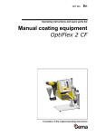
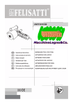
En
Operating instructions and spare parts list
XT10
Horizontal axis
Translation of the original operating instructions
V 02/13
Documentation XT10 Horizontal axis
© Copyright 2004 Gema Switzerland GmbH
All rights reserved.
This publication is protected by copyright. Unauthorized copying is
prohibited by law. No part of this publication may be reproduced,
photocopied, translated, stored on a retrieval system or transmitted in
any form or by any means for any purpose, neither as a whole nor
partially, without the express written consent of Gema Switzerland
GmbH.
OptiTronic, OptiGun, EasyTronic, EasySelect, EasyFlow and
SuperCorona are registered trademarks of Gema Switzerland GmbH.
OptiMatic, OptiMove, OptiMaster, OptiPlus, MultiTronic and Gematic are
trademarks of Gema Switzerland GmbH.
All other product names are trademarks or registered trademarks of their
respective holders.
Reference is made in this manual to different trademarks or registered
trademarks. Such references do not mean that the manufacturers
concerned approve of or are bound in any form by this manual. We have
endeavored to retain the preferred spelling of the trademarks, and
registered trademarks of the copyright holders.
To the best of our knowledge and belief, the information contained in this
publication was correct and valid on the date of publication. Gema
Switzerland GmbH makes no representations or warranties with respect
to the contents or use of this publication, and reserves the right to revise
this publication and make changes to its content without prior notice.
Printed in Switzerland
Gema Switzerland GmbH
Mövenstrasse 17
9015 St.Gallen
Switzerland
Phone: +41-71-313 83 00
Fax.: +41-71-313 83 83
E-Mail: [email protected]
Homepage: www.gemapowdercoating.com
V 02/13
Table of contents
General safety regulations
5
Safety symbols (pictograms) ...................................................................................5
Conformity of use ....................................................................................................5
A summary of the directives and standards ............................................................6
Product-specific safety measures ...........................................................................7
XT10 Horizontal axis ..................................................................................7
Special safety regulations for XT10 horizontal axis ................................................7
About this manual
9
General information .................................................................................................9
Function description
11
Field of application ................................................................................................11
Special characteristics...........................................................................................12
Reasonably foreseeable misuse ...........................................................................12
Technical data
13
XT10 Horizontal axis .............................................................................................13
Electrical data ...........................................................................................13
Mechanical data .......................................................................................13
Dimensions ...............................................................................................14
Versions....................................................................................................14
Set-up, assembly and commissioning
15
Design and function
17
Mechanical structure .............................................................................................17
Function description ..............................................................................................18
Safety and monitoring devices ..............................................................................18
Start-up
19
Assembly of the XT10 Horizontal axis ..................................................................19
Connecting the XT10 Horizontal axis to the ZA reciprocator ................................19
Preparation for start-up .........................................................................................21
General information ..................................................................................21
Reference point ........................................................................................21
Electrical connections / cable connections............................................................22
Checkpoints before switching on ..........................................................................22
Grounding / protection type ...................................................................................22
Hoses and cables ..................................................................................................23
Reference point and mechanical stops .................................................................23
Initial start-up .........................................................................................................24
XT10
Table of contents • 3
V 02/13
Maintenance
25
General information .............................................................................................. 25
Maintenance schedule .......................................................................................... 26
Drive unit ............................................................................................................... 26
Replacing the drive unit ........................................................................... 27
Drive belt ............................................................................................................... 28
Tensioning the drive belt .......................................................................... 28
Counter rollers ...................................................................................................... 29
Decommissioning, storage
31
Introduction ........................................................................................................... 31
Safety rules .............................................................................................. 31
Requirements on personnel carrying out the work .................................. 31
Storage conditions ................................................................................................ 32
Type of storage ........................................................................................ 32
Storage duration ...................................................................................... 32
Space requirements ................................................................................. 32
Physical requirements.............................................................................. 32
Hazard notes ............................................................................................ 32
Shut-down ............................................................................................................. 33
Decommissioning..................................................................................... 33
Cleaning ................................................................................................... 33
Maintenance during storage ................................................................................. 33
Maintenance schedule ............................................................................. 33
Maintenance works .................................................................................. 33
Packing, transport
35
Introduction ........................................................................................................... 35
Requirements on personnel carrying out the work .................................. 35
Packing material ................................................................................................... 35
Selection of packing material ................................................................... 35
Procedure when packing ......................................................................... 35
Transport ............................................................................................................... 35
Data concerning goods to be transported................................................ 35
Loading, transferring the load, unloading ................................................ 35
Fault clearance
37
Troubleshooting .................................................................................................... 37
Spare parts list
39
Ordering spare parts ............................................................................................. 39
XT10 Horizontal axis - spare parts list .................................................................. 40
Drive unit ............................................................................................................... 42
Running wheel bearing ......................................................................................... 44
Guide wheel bearing ............................................................................................. 46
Electrical module................................................................................................... 48
V 02/13
General safety regulations
This chapter sets out the fundamental safety regulations that must be
followed by the user and third parties using the XT10.
These safety regulations must be read and understood before the XT10
is put into operation.
Safety symbols (pictograms)
The following warnings with their meanings can be found in the Gema
operating instructions. The general safety precautions must also be
followed as well as the regulations in the operating instructions.
DANGER!
Danger due to electrically live or moving parts. Possible consequences:
death or serious injury
WARNING!
Improper use of the equipment could damage the machine or cause it to
malfunction. Possible consequences: minor injuries or damage to
equipment
INFORMATION!
Useful tips and other information
Conformity of use
1. The XT10 is built to the latest specification and conforms to the
recognized technical safety regulations and is designed for the
normal application of powder coating.
2. Any other use is considered non-compliant. The manufacturer
shall not be liable for damage resulting from such use; the user
bears sole responsibility for such actions. Gema Switzerland
GmbH must be consulted prior to any use of the XT10 for any
purposes or substances other than those indicated in our
guidelines.
3. Observance of the operating, service and maintenance
instructions specified by the manufacturer is also part of
conformity of use. The XT10 should only be used, maintained
XT10
General safety regulations • 5
V 02/13
and started up by trained personnel informed about and familiar
with the possible hazards involved.
4. Start-up (i.e. the execution of a particular operation) is forbidden
until it has been established that the XT10 horizontal axis has
been set up and wired according to the guidelines for machinery
(2006/42 EG). EN 60204-1 (machine safety) must also be
observed.
5. Unauthorized modifications to the XT10 horizontal axis exempt
the manufacturer from any liability from resulting damage.
6. The relevant accident prevention regulations, as well as other
generally recognized safety regulations, occupational health and
structural regulations are to be observed.
7. Furthermore, the country-specific safety regulations also must be
observed.
Explosion protection
Protection type
II 3D
IP54
A summary of the directives and standards
European directives RL
2006/42/EG
Machinery
94/9/EWG
Equipment and Protective Systems Intended for Use in
Potentially Explosive Atmospheres
2004/108/EG
Electromagnetic Compatibility (EMC)
EN European standards
EN ISO 12100-1:
2004
Safety of Machinery – Basic Concepts, General
Principles for Design –Part 1: Basic Terminology,
Methodology
EN ISO 12100-2:
2004
Safety of Machinery – Basic Concepts, General
Principles for Design – Part 2: Technical Principles
EN ISO 14121-1:
2007
Safety of Machinery – Risk Assessment, Part 1:
Principles
EN 60204-1: 2006
Safety of Machinery – Electrical Equipment of Machines
– Part 1: General requirements
EN 13980:2002
Potentially Explosive Atmospheres – Application of
Quality Systems
EN ISO 9001:
2008
Quality Management Systems – Requirements
EN 61241-0:2006
Electrical Apparatus for Use in the Presence of
Combustible Dust. General requirements
EN 61241-2-2:
1995
Electrical Apparatus for Use in the Presence of
Combustible Dust. Part 2: Methods
V 02/13
EN 61241-10:
2004
Electrical Apparatus for Use in the Presence of
Combustible Dust. Part 10: Classification of Areas
Where Combustible Dusts Are or May Be Present
EN 1127-1:2008
Explosive Atmospheres . Basic Concepts and
Methodology
Product-specific safety measures
XT10 Horizontal axis
The XT10 Horizontal axis is a constituent part of the system and is thus
integrated into the safety system of the plant.
If it is to be used in a manner outside the scope of the safety concept,
then corresponding measures must be taken.
Note:
For further information, see the more detailed Gema safety
regulations!
Special safety regulations for XT10 horizontal axis
1. The XM11 Horizontal axis may only be switched on and operated
after careful reading of this manual. Incorrect operation of the
axes control unit can lead to accidents, malfunctions or damage
to the plant.
2. Attention, the power of the horizontal axis is very much
stronger than that of a human being!
All axes must be secured against access during operation (see
local regulations).
Never stand under the Z carriage when the horizontal axis is
not operating!
3. The plugs and sockets of the axes control unit and the power unit
of the XT10 horizontal axis should only be unplugged when the
power supply is disconnected
4. The connecting cables between the control unit and the
horizontal axis must be laid in such a way, that they cannot be
damaged during axes operation. Please observe the local safety
regulations!
5. The maximum upper stroke limit of the reciprocator must
always be set with reference to the maximum height of the
booth gun slots. If an incorrect (too high) stroke limit is set, this
can lead to damage to the vertical axis and/or the booth!
Warning:
During a test run, it must be guaranteed that the unit is not damaged
by the test! In particular, the limitations of the stroke range have to
be observed (for further information, see chapter "Setting the upper
mechanical stop")!
XT10
General safety regulations • 7
V 02/13
6. When repairing the horizontal axis, both the axis control unit and
the horizontal axis must be disconnected from the mains
according to the local safety regulations!
7. Repairs may be done only by authorized Gema service centers.
Unauthorized conversions and modifications can lead to injuries
and damage to the equipment. The Gema Switzerland GmbH
guarantee would no longer be valid.
8. Only original Gema spare parts should be used! The use of
spare parts from other manufacturers will invalidate the Gema
guarantee conditions!
9. We point out that the customer himself is responsible for the safe
operation of the equipment. Gema Switzerland GmbH is in no
way responsible for any resulting damage.
V 02/13
About this manual
General information
This operating manual contains all the important information you require
for the working with the XT10 horizontal axis. It will safely guide you
through the start-up process and give you references and tips for the
optimal use of your new powder coating system.
Information about the function mode of the individual system components
- booth, gun control unit, manual gun or powder injector - should be
referenced to their corresponding documents.
XT10
About this manual • 9
V 02/13
Function description
Field of application
The XT10 Horizontal axis is used for the coating of parts with different
widths. By coating in this way, the powder guns must be driven into each
corresponding position for every given width. The XT10 Horizontal axis
can be used in connection with a ZA reciprocator.
XT10 Horizontal axis with ZA reciprocator
XT10
Function description • 11
V 02/13
Special characteristics
The XT10 Horizontal axis is a feeding axis and has the following
characteristics:
-
Same control as for the ZA reciprocator
-
Freely adjustable speed setting on the axes control unit
-
Built-in leveling pads
-
Minimum space requirement
-
No additional space required for dismantling and service
works
-
Low overall height
-
Manually movable when the control unit is switched off
-
Intermediate and larger sizes available in steps of 50 mm
(For more information about the controlling of the axis, see the axes
control unit operating manual)
Reasonably foreseeable misuse
12 • Function description
-
Operation in rooms with gases
-
Horizontal axis is not anchored firmly to the floor
-
The axis mounted on the horizontal axis is not fixed properly
-
Incorrect programming of the end points and travel distance
-
Operation without the proper training
-
Operating the horizontal axis without the protective fence
XT10
V 02/13
Technical data
XT10 Horizontal axis
Electrical data
XT10
Power supply
Tolerance
Power consumption
Frequency
Protection type
Isolation
Control unit
Temperature range
230 VAC (from control unit)
± 10%
0.3 kW
50/60 Hz
IP54
Class F
CM-30
10 °C - 40 °C
(50 °F - 104 °F)
Mechanical data
XT10
Speed
Acceleration
Position detection
Reference point
Zero point
XT10
0,01-0,6 m/s
0,1-2,0 m/s²
with incremental pulse generator
corresponds to the zero point
selectable in both end positions
Travel distance min.
400 mm
Travel distance max.
on request
Technical data • 13
V 02/13
Dimensions
Total length = travel distance + 750
50 Free space
50 Free space
Horizontalachse XT10 - Abmessungen
Versions
The XT10 Horizontal axis is available in two versions with different travel
distances.
Travel distance length
Weight
14 • Technical data
XT10-10
XT10-14
1000 mm
1400 mm
150 kg
166 kg
XT10
V 02/13
Set-up, assembly and commissioning
Warning:
If a free-standing horizontal axis is not anchored firmly to the floor,
uncontrolled movement of the machine or insufficient stability can
cause injuries.
- Firmly anchor the horizontal axis to the floor if it is not mounted to
another axis of motion
Warning:
The movement of the reciprocator can cause injuries.
- Erect a protective fence around the reciprocator so that there is no
danger of injury during normal operation.
Danger:
Injuries can occur inside the protective fence due to the movement
of the reciprocator!
- In order to enter the inner area, the door interlocks must be
released by the control unit. This release signal may only be
activated by technical personnel.
Except for normal operation, all other operating modes must be set up by
an authorized technical representative.
XT10
Set-up, assembly and commissioning • 15
V 02/13
Design and function
Mechanical structure
The XT10 Horizontal axis consists of the following components:
5
1
6
4
2
3
XT10 Horizontal axis - mechanical structure
XT10
1
Drive unit - complete
4
Frame
2
Leveling bolt
5
Rubber buffer
3
Baseboard
6
Carriage
Design and function • 17
V 02/13
Function description
-
The XT10 Horizontal axis is a feeding axis for adjusting the
gun position to the parts to be coated
-
The XT10 Horizontal axis position detection takes place by a
pulse generator installed onto the drive unit
-
The drive takes place by the drive unit, installed onto the axis
carriage (motor with spur gear and pulse generator) and the
toothed belt, installed into the travel frame
Safety and monitoring devices
All moving axes must be secured by the customer before start-up and
during operation by providing fencing (see the local regulations)!
18 • Design and function
XT10
V 02/13
Start-up
Assembly of the XT10 Horizontal axis
The axis must be leveled, in order to ensure a safe and perfect operation.
After positioning, the XT10 Horizontal axis must be firmly fixed on the
floor.
Connecting the XT10 Horizontal axis to the ZA
reciprocator
1. The cables to be connected are lying loose on the carriage plate
of the horizontal axis
XT10 Horizontal axis with connection cable
2. Both cables must be inserted into the cable duct in the ZA
reciprocator (1)
3. Loosen the screws on the rear side of the ZA reciprocator and
pull out the electrical modules
XT10
Start-up • 19
V 02/13
XT
ZA
Electrical modules in the ZA reciprocator
4. Break out the required opening in the feed-through rubber and
pull through the cables.
1
Cable feed-through in the ZA reciprocator
5. Connect the cable (according to the enclosed wiring diagram)
6. Push back the electrical modules and fasten them
20 • Start-up
XT10
V 02/13
Preparation for start-up
Warning:
Before connecting or switching on the horizontal axis, read
carefully these operating instructions!
Before the horizontal axis is put into operation, the upper stroke
limit must be set on the reciprocator control unit!
(see the user manual of the axis control unit)
General information
Warning:
Before start-up works are done, make certain that nobody can
switch on the horizontal axis! Switch off and lock the mains switch!
Before starting up, the following checks should be done:
-
Check the gun holder and hose holder if they are firmly fitted.
Mount the gun holder in such a way that they do not hit the
bottom of the booth slots on start-up and cause damage
-
Lay out the cables and hoses in such a way that even at the
highest stroke no strain can arise
-
Make sure that no guns can collide with the work pieces
-
Check the grounding of the guns and hose carriers
-
Check if the upper and the lower reversing point of the Z
carriage are set correctly. The stroke length of the
reciprocator must be in the range of the booth opening
(collision danger!)
-
Make sure that the automatic guns cannot collide with the
work pieces (incorrectly adjusted stroke parameters on the
reciprocator control unit)
Reference point
At every start-up after the mains have been interrupted, the reference
point of the reciprocator must be referred again (see "Reference point
and mechanical stops"). After the reference point is reached, the
reciprocator begins to carry out the movements set on the reciprocator
control unit.
Before the horizontal axis is put into operation, the travel distance must
be set on the axis control unit (see therefore the corresponding axis
control unit operating manual)!
Warning:
Incorrect setting of the travel distance can cause damages to the
reciprocator, to the booth and/or to the applicators!
XT10
Start-up • 21
V 02/13
Electrical connections / cable connections
Electrical
module
Electrical
module
CM-30 control - XT10 - connections
Note:
All internal connections between the XT10 axis and the electrical
module are to be made according to the enclosed wiring diagram.
Checkpoints before switching on
Before switching on, the following checks should be done:
-
Check if the cables and hoses are laid out correctly
-
Check if the guns have a clear run and do not touch the
booth slots
-
Check the distance between the work pieces and the guns
Warning:
Before connecting or switching on the horizontal axis, read
carefully these operating instructions!
Grounding / protection type
All metal parts of the horizontal axis must be grounded according to the
local safety regulations. The grounding screw is located on the horizontal
axis base.
All electrical installations are implemented in accordance to VDE IP54
protection type regulations!
22 • Start-up
XT10
V 02/13
Hoses and cables
All movable hoses and cables must be laid out in such a way that they
are neither subjected to any loads nor can hang on other parts. The
electric cables of the reciprocators must be protected from mechanical
damage.
Reference point and mechanical stops
The reference point serves as starting point for the axis control unit for
calculating the reversing points as well as the maximum travel distance.
Each time the reciprocator is switched on, the control unit requests that
the carriage travels to the reference point (zero point). The carriage
travels to the mechanical stop, which means onto the rubber buffer.
The control unit notes this and gives the distance how far the carriage
must travel from this position to decompress the rubber buffer. The
standard value for the XT axis is 30, that means 30 mm away from the
mechanical stop. For this reason, the Axis control unit must be
programmed in such a way that the reference point is always 30 mm
before the lowest mechanical stop (zero point).
Attention!
In order to avoid damages to the booth, to the gun holders etc. the
reference point must be set before the first start-up!
Rubber buffer
XT10 horizontal axis - reference point and mechanical stops
Warning:
In order to avoid damages to the booth or the gun holders, the
reference point must be checked before the first start-up and if
necessary, reset!
It must be noted that the axes in reference travel moves up to 30
mm behind the control’s zero point!
Warning:
The reference point must be referenced before each start-up (at
each switching on, after an interruption of the power supply etc.)!
XT10
Start-up • 23
V 02/13
Initial start-up
Danger!
Never stand on the horizontal axis or under the carriage of the
vertical axis when it is in operation! Danger of accident!
Warning:
The power of the horizontal axis is much stronger than that of a
human being!
All axes must be secured against admittance during operation (see
local regulations).
Before start-up the horizontal axis, the following points must be noted:
-
The frame and the drive carriage of the axis must be
grounded! The grounding of the frame must be done by the
customer
-
Adapt the system parameters in the axes control unit (see
the axes control unit operating instructions)
In addition, the following checks are necessary before the initial start-up:
24 • Start-up
-
Travel distance
Check by moving manually, as well as in accordance to the
axes control operating manual
-
Control unit
Check the cable connections (correct connections, squeezed
parts, cable lengths, cable movement etc.)
-
Stability
Horizontal axis and carriage plate must be stable!
XT10
V 02/13
Maintenance
Danger:
Injuries can occur inside the protective fence due to the movement
of the reciprocator!
- In order to enter the inner area, the door interlocks must be
released by the control unit. This release signal may only be
activated by technical personnel.
General information
Warning:
Before maintenance work can be carried out on the horizontal axis,
it must be ensured that the horizontal axis cannot be turned on by
third parties!
The horizontal axis has to be free of load and disconnected from
mains!
The XT10 horizontal axis was designed to operate with a minimum of
maintenance. The motor gear box is self-lubricating and maintenancefree.
Regular maintenance and inspection of the horizontal axis increases the
working reliability and avoids damages, repair downtimes etc.!
XT10
Maintenance • 25
V 02/13
Maintenance schedule
Note:
The following maintenance schedule is based on operation of 8
hours per day.
Time interval
Maintenance works
weekly
-
Blow off the outside of the horizontal axis with
compressed air or clean it with a soft cloth at least once
a week.
monthly
-
Check the drive unit gearbox for oil loss
-
Check the interior of the horizontal axis for deposits of
powder dust and if present, clean it
-
Check the drive belt for wear and tension
-
Check the rollers on the carriage for free movement and
wear
-
Check the running surfaces for wear and deposits and, if
present, clean them
every 6 months
Note:
The parts, which are to be replaced during maintenance work, are
available as spare parts. Please refer to the spare parts list too!
Drive unit
Danger:
During assembly, cleaning, maintenance and commissioning when
close to energized components, an electrical shock can cause
serious injury or death.
- All work must be carried out only by technical personnel and when
no power is applied!
The motor gear box is self-lubricating and maintenance-free.
Observe the contamination of the enclosure - strong contamination on
the outside can increase the operating temperature of the drive unit!
Therefore, clean the drive unit from time to time (with a vacuum cleaner
etc.). Check the drive unit gearbox monthly for oil loss. If the drive unit
gearbox has to be changed for any reason, the complete unit has to be
replaced!
26 • Maintenance
XT10
V 02/13
Replacing the drive unit
WARNING!
There is the risk of burns if contact is made with electrical
components that have become overheated!
- All work must be carried out only by technical personnel and when
no power is applied!
If it is necessary to replace a drive unit gearbox, the complete motor unit
must be dismantled from the horizontal axis. Therefore, the horizontal
axis has to be free of load and disconnected from mains.
14
8
12
20
24
16
XT10 Horizontal axis - drive unit
Procedure:
1. Remove the Z axis from the carriage plate
2. Remove the carriage plate
3. Remove both cover panels
4. Loosen the tensioning screws, so that the drive belt is slack
5. Remove the drive belt
6. Uncouple the motor power supply cable, in order to use it with
the new motor again
7. Remove the incremental pulse generator (8)
8. Loosen the fixing screws (12 - 4 pieces) and take out the motor
drive unit
9. Loosen the screws (24) and remove the guide rollers (20)
10. Loosen the clamping set (16) and remove the drive wheel
11. Loosen the screws (14) and remove the holder from the motor
drive unit
The installation takes place exactly in the reverse order!
XT10
Maintenance • 27
V 02/13
Drive belt
Warning:
Injuries can arise if fingers, hair or articles of clothing get caught
between the drive belt and the drive wheel or toothed wheel.
- All work must be carried out only by technical personnel
The toothed drive belt should be checked regularly because it is exposed
to large loads when in operation.
The drive belt should be checked for wear and tension every 6
months. Powder deposits should be removed with a vacuum
cleaner, because this can influence the quiet running and shorten
the service life of the drive belt
-
Switch on the horizontal axis and check the drive belt for
elongation or wear (noisy running, strong vibration of the belt
when reversing the direction of travel)
Warning:
For safety reasons, two people should always carry out the
following maintenance work!
Tensioning the drive belt
11
10
6
8
23
XT10 Horizontal axis - Tensioning the drive belt
28 • Maintenance
-
Clamp the drive belt (23) with the clamp block (8) and tighten
the screws (6)
-
Tension the drive belt with the tensioning screw (11), so that
the drive belt will deflect 2-3 cm
-
Tighten the lock nut (10)
XT10
V 02/13
Counter rollers
If the X carriage starts to vibrate excessively during operation, especially
at the reversing points, in most cases the cause lies in too much play in
the carriage rollers, or even loose rollers!
13
12
14
XT carriage - rollers
In this case, proceed as follows:
1. Switch off the electric power
2. Remove the carriage and the panels
3. Loosen the roller screw (14) lightly
4. Loosen the lock nut (12)
5. Adjust the roller pressure with the screw (13), in such a way that
the roller can just be turned by hand
6. Tighten the roller screw (14)
7. Tighten the lock nut (12)
8. Fit the panels again and fasten them firmly
The carriage should run evenly and quietly again!
XT10
Maintenance • 29
V 02/13
Decommissioning, storage
Introduction
Safety rules
Before lifting a reciprocator off of its horizontal axes, it must be secured
from falling over with a lifting device such as a crane, fork lift, etc. The
point of attachment is the eye bolt (A) at the top of the reciprocator.
A
ZA.. reciprocator - Top view
The horizontal axes should be lifted up using lifting straps:
Requirements on personnel carrying out the
work
All work should be carried out only by authorized technical personnel.
XT10
Decommissioning, storage • 31
V 02/13
Storage conditions
Type of storage
Horizontal axes can be stacked.
Storage duration
If the physical conditions are maintained, the unit can be stored
indefinitely.
Space requirements
The space requirements correspond to the sizes of the axes of motion.
The load-bearing capacity of the floor should be at least 200 kg/m².
There are no special requirements concerning distance to neighboring
equipment.
Physical requirements
Storage must be inside a dry building at a temperature between 5 – 50 °C.
Hazard notes
There is no danger to personnel or the environment if the unit is stored
properly.
32 • Decommissioning, storage
XT10
V 02/13
Shut-down
Decommissioning
Before starting any kind of work, the axes of motion must be
disconnected from the power supply:
-
Unplug the power cable
-
Unplug the ground cable
Cleaning
The running surfaces of horizontal axis must be thoroughly cleaned.
Maintenance during storage
Maintenance schedule
No maintenance schedule is necessary.
Maintenance works
During long-term storage, periodically perform a visual check for
corrosion.
XT10
Decommissioning, storage • 33
V 02/13
Packing, transport
Introduction
This chapter describes special precautions that must be taken during
internal transport of the product if:
-
the customer himself must pack, transport and ship the
product, such as to have renovations or service work carried
out by the manufacturer
-
the product must be shipped for disposal (recycling).
or
Requirements on personnel carrying out the
work
All work must be carried out by personnel trained in packing machines.
Packing material
Selection of packing material
Suitably stable wood packing material must be used.
Procedure when packing
Transport the unit only in a horizontal position.
Transport
Data concerning goods to be transported
The space requirements correspond to the size of the axes of motion
plus the packaging.
Loading, transferring the load, unloading
At least one fork lift must be available.
XT10
Packing, transport • 35
V 02/13
Fault clearance
Troubleshooting
Warning:
Faults may be fixed by trained personnel only!
Error/fault
Procedures/remedy
Reciprocator with carriage plate is
waggling
Check the connecting bolts between
reciprocator, carriage plate and the
carriage for tightness
Adjust the counter rollers without
clearance by the corresponding
screws on the running wheel
bearing/guide wheel bearing (see
also the spare parts list)
Warning:
In no case press the counter rollers,
otherwise they wear quickly!
Reference point not reached
Remove the powder accumulation on
the running surfaces
Check for a foreign body - if present,
remove it
Check the XT10 Horizontal axis for
proper running (move manually)
Consider the indications in the axes
control unit operating manual!
XT10
Fault clearance • 37
V 02/13
Spare parts list
Ordering spare parts
When ordering spare parts for powder coating equipment, please indicate
the following specifications:
-
Type and serial number of your powder coating
equipment
-
Order number, quantity and description of each spare
part
-
Type XT10
Serial number 1234 5678
-
Order no. 203 386, 1 piece, Clamp - Ø 18/15 mm
Example:
When ordering cable or hose material, the required length must also be
given. The spare part numbers of this bulk stock is always marked with
an *.
Wearing parts are always marked with a #.
All dimensions of plastic hoses are specified with the external and
internal diameter:
Example:
Ø 8/6 mm, 8 mm outside diameter (o/d) / 6 mm inside diameter (i/d)
WARNING!
Only original Gema spare parts should be used, because the
explosion protection will also be preserved that way. The use of
spare parts from other manufacturers will invalidate the Gema
guarantee conditions!
XT10
Spare parts list • 39
V 02/13
XT10 Horizontal axis - spare parts list
Attention!
When ordering toothed belts, indicate the toothed belt length
(according to travel distance + 855 mm).
By replacing the toothed belt, screw in the grub screw, so that the
steel cables in the toothed belt are touched and the grounding is
ensured!
1
ZA.. carriage plate
387 355
2
Hexagon shakeproof screw - M8x20 mm
244 422
3
Hexagon screw - M6x10 mm
4
Cover panel - indicate the travel distance
5
Cover panel - firm side
372 463
6
Hexagon screw - M8x50 mm
213 993
7
Headless screw - M8x60 mm
258 482
8
Clamping plate
372 420
9
Threaded bolt - M10x140 mm
258 474
10
Hexagon nut - M10
215 589
11
Clamp plate
345 067
12
Hexagon nut - M12
215 597
13
Threaded bolt - M12x115 mm
372 676
14
Washer - Ø 13/24x2.5 mm
215 830
15
Washer - M6 (for countersunk-head screw)
258 431
16
Countersunk-head screw - M6x12 mm
214 680
17
Baseboard
372 404
18
Rubber buffer - Ø 35x40 mm, M8
211 664
19
Buffer holder
389 285
20
Hexagon shakeproof screw - M6x16 mm
244 503
22
Allen grub screw - M6x10 mm
214 841
23
Drive belt
25
Running wheel bearing - complete (see corresponding spare parts list)
28
XT10 drive unit - complete (see corresponding spare parts list)
29
Guide wheel bearing - complete (see corresponding spare parts list)
1001 081
on request
103 730#*
XT10 Electrical module on ZA05 (not shown, see corresponding spare parts list)
* Please indicate length
# Wearing part
40 • Spare parts list
XT10
V 02/13
XT10 Horizontal axis - spare parts
2
1
5
3
3
4
6
7
9
8
10
20
11
12
13
17
2
22
18
23
19
14
28
15
11
16
25
29
XT10 Horizontal axis - spare parts list
XT10
Spare parts list • 41
V 02/13
Drive unit
1
Motor/gearbox unit - 0.18 kW, complete (pos. 1-5)
- for XT Axes with serial numbers 18301.xxxx (see Rating plate)
1003 823
- for XT Axes with serial numbers 18302.xxxx (see Rating plate)
1008 445
2
Torque support - Ø 6 mm
1003 819
3
Locknut - M6
1003 822
4
Washer - Ø 6.4/16x1.6 mm
5
Cable bush - ID 5 mm
1003 821
6
Motor cable - L=2.5 m
387 169
8
Incremental pulse generator
268 925
215 805
10
Hexagon ribbed nut - M12
11
Hexagon shakeproof nut - M6
244 430
12
Hexagon screw - M10x20 mm
214 108
13
Ribbed washer - M10
237 981
14
Countersunk Allen screw - M6x25 mm
241 598
15
Toothed belt wheel
1003 797
1)
1003 814
1)
16
Clamping set - Ø 20/47x22 mm
17
Spacer ring - Ø 20/12.1x3.7 mm
18
Deep groove ball bearing - Ø 12/32x10 mm
245 720
19
Snap ring - A-32
235 741
20
Guide roller
1003 793
21
Spacer ring - Ø 20/12.1x25 mm
1003 812
22
Roller fixing plate - L=120 mm
1003 796
23
Ribbed washer - M12
237 973
24
Hexagon screw - M12x80 mm
221 325
1)
257 583
1003 795
If these parts must be replaced, clean off all grease before assembly!
42 • Spare parts list
XT10
V 02/13
Drive unit
2
5
6
3
1
11
8
15
4
16
10
22
21
12
13
24
17
18
XT10 Horizontal axis - drive unit
23
14
19
20
19
18
17
XT10
Spare parts list • 43
V 02/13
Running wheel bearing
Running wheel bearing - complete, FS
1003 808
Running wheel bearing - complete, LS
1003 806
1
Running wheel bearing (support) - FS
1003 809#
1
Running wheel bearing (support) - LS
1003 807#
3
Counter roller
390 658#
4
Bearing bolt
1003 813
5
Running wheel - Ø 73 mm
6
Deep groove ball bearing - Ø 10/35x11 mm
201 359#
7
Deep groove ball bearing - Ø 15/52x15 mm
258 415#
8
Snap ring - I-35
216 135
9
Snap ring - A-10
256 358
10
Snap ring - A-25
237 094
11
Ribbed washer - M8
242 870
12
Hexagon nut - M6
205 095
13
Hexagon screw - M6x25 mm
213 845
14
Hexagon screw - M8x10 mm
213 900
1003 805#
# Wearing part
FS
LS
XT10 Horizontal axis - running wheel bearing
44 • Spare parts list
XT10
V 02/13
Running wheel bearing
7
1
5
14
10
11
12
13
4
8
6
3
9
Running wheel bearing - FS
XT10
Spare parts list • 45
V 02/13
Guide wheel bearing
Guide wheel bearing - complete, LS
1003 803
Guide wheel bearing - complete, FS
1003 811
1
Guide wheel bearing (support) - LS
1003 804#
1
Guide wheel bearing (support) - FS
1003 810#
4
Guide profile
5
Guide wheel - Ø 73 mm
6
Counter plate
372 382
7
Counter roller
390 658#
8
Bearing bolt
1003 813
9
Deep groove ball bearing - Ø 10/35x11 mm
201 359
10
Deep groove ball bearing - Ø 15/52x15 mm
258 415
11
Snap ring - I-35
216 135
12
Snap ring - A-10
256 358
13
Snap ring - A-25
237 094
14
Ribbed washer - M8
242 870
15
Hexagon nut - M6
205 095
16
Locknut - M8
221 317
17
Countersunk screw K-SI - M8x70 mm
258 440
18
Hexagon screw - M6x25 mm
213 845
19
Hexagon screw - M8x10 mm
213 900
372 374#
1003 805#
# Wearing part
LS
FS
XT10 Horizontal axis - guide wheel bearing
46 • Spare parts list
XT10
V 02/13
Guide wheel bearing
17
4
10
6
1
16
19
5
13
14
15
18
8
11
9
7
12
Guide wheel bearing - LS
XT10
Spare parts list • 47
V 02/13
Electrical module
Electrical module - complete
1003 983
1
Position regulator CDB
1003 986
2
CAN bus cable 0.55 m
386 995
3
CAN bus cable 1.0 m
391 620
4
CAN T-distribution box
265 772
5
Adhesive seal strip - 9x2 mm
100 250*
* Please indicate length
2
1
5
3
4
XT10 Horizontal axis - electrical module in the ZA05 Reciprocator
48 • Spare parts list
XT10
V 02/13
XT10
Spare parts list • 49