1
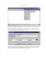
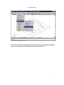
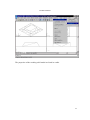
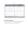
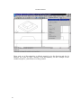
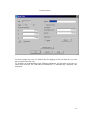
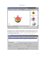
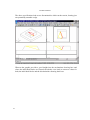
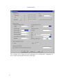
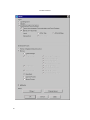
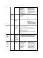
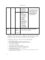
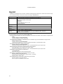
AutoBlock Manual ..the selected Blocks (as solids) only, or ..the Undisturbed, original Rock Surface. In addition, the Trace Lines may be displayed where the discontinuities outcrop, or the Points on Trace Lines, where the intersections of the discontinuities outcrop, either at the top end or at the bottom end. For the latter also the Resultant, the Factor of Safety and some Attributes may be displayed, e.g. the failure mode. Condensing the representation of blocks to trace lines or even just points on them may be recommendable in the case of many blocks. An accumulation may indicate pronounced stability problems in this area. By enabling Factor of Safety / Mode / Direction, specific Forces (e.g. Normal Forces) and Attributes in the group Data corresponding information may be displayed. Factor of Safety / Mode / Direction, resultants and Attributes are displayed at the center of gravity of the blocks. Individual forces are displayed at their point of application. If they are projected on the surface (see editing point forces) they are displayed at the nearest intersection with the block selected. The scalar value Factor of Safety is displayed in the form of a vector: the length corresponds to the Factor of Safety (scaled according to Size of Vectors / Length of Direction Vectors in Preferences), and the orientation to the direction of sliding. The forces are scaled according to Size of Vectors / Forces Scaling Vectors in Preferences. The buttons in the group Show allow one to display more information about the blocks. The button Show displays them graphically. The button Change View, which is available in many dialog boxes, branches immediately to the AutoCAD level by retaining the content and layout of the last drawing viewed. There the whole power of AutoCAD is at the user's disposal. 72