1
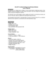
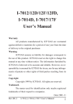
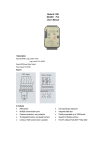
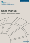
DAM-3059 User’s Manual Beijing ART Technology Development Co., Ltd. DAM-3059 User’s Manual V6.16 DAM-3059 Module Introduction Features 8-CH analog input module Input Type: V, mA Each channel range can be configured independently Channel Input: 6DI, 2SE (default)or 8DI Sampling Rate: 10Hz 16-bit resolution Accuracy: ±0.1% Input Impedance: 8MΩ Zero Drift: 20uV/℃ Full Scale Drift: 25ppm /℃ CMR @ 50/60Hz: 86dB NMR @ 50/60Hz: 100dB Isolation Voltage: 3000VDC Built-in Watchdog Power Supply: unregulated +10 ~ +30 VDC Power consumption: 1.3W @ 24VDC Easy to operate DAM-3059 utility software can help you to select input configuration, set the operating parameter for your process control needed. Industrial Design DAM-3059 was designed to use in industrial environment. It can be installed in standard DIN rail inside the cabinet. And it can be powered by unregulated 10~30VDC to meet the various power supplied source in field. It also withstands ambient temperature up to 60℃ and resists the effects of vibration and mechanical shock. 2 DAM-3059 User’s Manual V6.16 Wiring & Installation Power supply requirements: unregulated +10 VDC ~ +30 VDC. "+Vs" is a positive, and "GND" is ground. "DATA +" and "DATA-" connect with "DATA +" and "DATA-"(or "A" and "B") of RS-232/RS-485 transformation module, then connect transformation module with computer, do not hot plug carefully. The power indicator flashes after wiring is correct, then you can communication with the host computer. According to the label directs color to wiring: +Vs (R) Red GND(B) Black DATA+ (Y) Yellow DATA- (G) Green It can connect with DAM-3212, show as the following: 3 DAM-3059 User’s Manual V6.16 DAM-3059 Fig. 1 DAM-3059 Drawing DAM-3059 can be installed in standard DIN rail inside the cabinet, it also can be installed by stacking mode. Fig.2 standard DIN installation 4 DAM-3059 User’s Manual V6.16 Fig.3 stack installation Jumper Setting Jumper JP1 for select the pin INIT*/IN7Select 8 differential inputs mode, the pin INIT*/IN7- is set to IN7- Select INIT* mode, the pin INIT*/IN7- is set to INIT* Application Wiring Reset Connection: Select INIT* mode and shorted the INIT * and GND shorted, add +10 ~ +30 VDC between +Vs and GND, power on, the module indicator quickly flashes three times, power off until the indicator stops flashing, disconnect the INIT * and GND, then reset the module has been completed. After reset successfully, the module restore the factory default values: Module Address: 1 Baud Rate: 9600 5 DAM-3059 User’s Manual V6.16 Analog Input Connection Fig. 4 Analog input (0~5 channel) wiring diagram Fig.5 Analog input (6~7 channel) wiring diagram (while the jumper JP1 setting is 8 differential inputs mode) Fig.6 Analog input (6~7 channel) wiring diagram (while the jumper JP1 setting is INIT* mode) Default Setting If the module’s address or baud rate is wrong, or forget the last modified value, the module can be reverted to default settings. Steps: Short-circuit the “INIT*” and “GND” when there is no power; power-on for 3 seconds, power off, disconnect “INIT*” and “GND”. The module is reverted to the default settings. Address: 00 6 DAM-3059 User’s Manual V6.16 Baud Rate :9600bps Noparity The serial port default work mode: parity bit: none data bits: 8 stop bit: 1 Code Configuration Table Baud Rate Configuration Code Table Code 00 01 02 03 04 05 06 07 Rate 1200 2400 4800 9600 19200 38400 57600 115200 Analog Input Range Configuration Code Table Signal Type Range 0~10mA mV, V, mA Code 00 ±100mV 03 ±150mV 04 ±500mV 05 ±1V 06 ±2.5V 07 ±5V 08 ±10V 09 ±20mA 0A 0~20mA 0B 4~20mA 0C 0~5V 0D 0~10V 0E 0~2.5V 0F Pin Definition Pin Name Function 1 IN5+ Analog input 5-ch positive port 2 IN5- Analog input 5-ch negative port 3 IN6+ Analog input 6-ch positive port 4 IN6- Analog input 6-ch negative port 5 IN7+ Analog input 7-ch positive port 6 INIT*/IN7- reset pin, connect with(B)GND, then power-on to reset/when differential input, it is the 7-ch negative port 7 (Y)DATA+ RS-485 positive 8 (G)DATA- RS-485 negative 9 (R)+Vs DC Power Supply (+),+10~+30V DC 7 DAM-3059 User’s Manual V6.16 10 (B)GND DC Power Supply (-) 11 IN0+ Analog input 0-ch positive port 12 IN0- Analog input 0-ch negative port 13 IN1+ Analog input 1-ch positive port 14 IN1- Analog input 1-ch negative port 15 IN2+ Analog input 2-ch positive port 16 IN2- Analog input 2-ch negative port 17 IN3+ Analog input 3-ch positive port 18 IN3- Analog input 3-ch negative port 19 IN4+ Analog input 4-ch positive port 20 IN4- Analog input 4-ch negative port 8