1
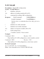
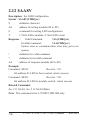
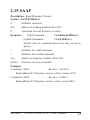
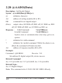
I-7012/12D/12F/12FD,
I-7014D, I-7017/17F
User’s Manual
Warranty
All products manufactured by ICP DAS are warranted
against defective materials for a period of one year from the date
of delivery to the original purchaser.
Warning
ICP DAS assume no liability for damages consequent to
the use of this product. ICP DAS reserves the right to change this
manual at any time without notice. The information furnished by
ICP DAS is believed to be accurate and reliable. However, no responsibility is assumed by ICP DAS for its use, nor for any infringements of patents or other rights of third parties resulting from its
use.
Copyright
Copyright 1999 by ICP DAS. All rights are reserved.
Trademark
The names used for identification only maybe registered
trademarks of their respective companies.
Rev:B1.2
Date:2001-11
I-7012, I-7014, I-7017 User’s Manual
1
Table of Contents
1. Introduction .....................................................5
1.1 More Information.......................................5
1.2 Pin Assignment ..........................................6
1.3 Specifications ............................................9
1.4 Block Diagram .........................................12
1.5 Wire Connection......................................14
1.6 Quick Start ..............................................16
1.7 Default Setting .........................................16
1.8 Jumper Setting .........................................16
1.9 Calibration ...............................................17
1.10 Configuration Tables .............................18
2. Command .......................................................20
2.1 %AANNTTCCFF ...................................24
2.2 #** ...........................................................26
2.3 #AA .........................................................27
2.4 #AAN ......................................................28
2.5 $AA0 .......................................................29
2.6 $AA1 .......................................................30
2.7 $AA2 .......................................................31
2.8 $AA4 .......................................................32
2.9 $AA5VV .................................................33
2.10 $AA6 .....................................................34
2
I-7012, I-7014, I-7017 User’s Manual
Rev:B1.2
2.11 $AA8 .....................................................35
2.12 $AA8V ..................................................36
2.13 $AA9(Data) ...........................................37
2.14 $AAA ....................................................38
2.15 $AAF .....................................................39
2.16 $AAM....................................................40
2.17 ~AAO(Data) ..........................................41
2.18 ~AAEV ..................................................42
2.19 @AADI..................................................43
2.20 @AADO(Data)......................................44
2.21 @AAEAT ..............................................45
2.22 @AAHI(Data) .......................................46
2.23 @AALO(Data) ......................................47
2.24 @AADA ................................................48
2.25 @AACA ................................................49
2.26 @AARH ................................................50
2.27 @AARL ................................................51
2.28 @AARE ................................................52
2.29 @AACE ................................................53
2.30 $AA3 .....................................................54
2.31 $AA5 .....................................................55
2.32 $AA6(SL)(SH) ......................................56
2.33 $AA7(TL)(TH)......................................57
2.34 $AAA ....................................................58
Rev:B1.2
I-7012, I-7014, I-7017 User’s Manual
3
2.35 $AAAV ..................................................59
2.36 ~** .........................................................60
2.37 ~AA0 .....................................................61
2.38 ~AA1 .....................................................62
2.39 ~AA2 .....................................................63
2.40 ~AA3EVV .............................................64
2.41 ~AA4 .....................................................65
2.42 ~AA5PPSS ............................................66
3. Application Note ............................................67
3.1 INIT* pin Operation ................................67
3.2 Module Status..........................................67
3.3 Dual Watchdog Operation .......................68
3.4 Digital Input and Event Counter..............68
3.5 Digital Output ..........................................68
3.6 High/Low Alarm ......................................69
3.7 Transmitter ...............................................69
3.8 Linear Mapping .......................................70
4
I-7012, I-7014, I-7017 User’s Manual
Rev:B1.2
1. Introduction
I-7000 is a family of network data acquisition and control
modules. They provide analog-to-digital, digital-to-analog, digital
input/output, timer/counter and other functions. These modules can
be remote controlled by a set of commands. The common features
of analog input modules are given as follows :
z
3000VDC Isolated analog input.
z
24-bits sigma-delta ADC to provide excellent accuracy.
z
Software calibration
The I-7012 is a single channel analog input module with
high/low alarm function. The I-7012D is the I-7012 with a 4½ digit
LED display. The I-7012F/12FD is a I-7012/12D with high speed
analog input function. The I-7014D is I-7012D with Linear Mapping function and support +15V loop power for transmitter. The I7017 is a 8-channel analog input module. The I-7017F is I-7017
with high speed analog input function.
1.1 More Information
Refer to “I-7000 Bus Converter User Manual” chapter 1
for more information as following:
1.1 I-7000 Overview
1.2 I-7000 Related Documentation
1.3 I-7000 Command Features
1.4 I-7000 System Network Configuration
1.5 I-7000 Dimension
Rev:B1.2
I-7012, I-7014, I-7017 User’s Manual
5
1.2 Pin Assignment
6
I-7012, I-7014, I-7017 User’s Manual
Rev:B1.2
Rev:B1.2
I-7012, I-7014, I-7017 User’s Manual
7
8
I-7012, I-7014, I-7017 User’s Manual
Rev:B1.2
1.3 Specifications
I-7012/I-7012D
Max Input Frequency : 50 Hz
Analog Input
Min. Pulse Width : 1 mS
Input Channel :
1
Displayed LED
Input Type :
4½ digits (for I-7012D)
mV, V, mA(with external
Power Supply
125 ohms resistor)
Input : +10 to +30VDC
Sampling Rate :
Consumption :
10 Samples/Second
1.3W for I-7012
Bandwidth : 5.24 Hz
1.9W for I-7012D
Accuracy : ±0.05%
Zero Drift : 20µV/°C
Span Drift : 25ppm/°C
CMR : 86dB
Input Impedance : 20M Ohms
Isolation : 3000VDC
Digital Output
Output Channel : 2
Open Collector to 30V
Output Load : sink 30mA max
Power Dissipation : 300mW
Digital Input
Input Channel : 1
Logic Level 0 : +1V max
Logic Level 1 : +3.5 to 30V
Event Counter
Rev:B1.2
I-7012, I-7014, I-7017 User’s Manual
9
I-7012F/I-7012FD
Analog Input
Input Channel :
1
Input Type :
mV, V, mA(with external
125 ohms resistor)
Fast Mode Sampling Rate :
100 Samples/Second
Fast Mode Bandwidth : 52.4 Hz
Fast Mode Accuracy : ±0.25%
Normal Mode :
Same as I-7012
Input Impedance : 20M Ohms
Isolation : 3000VDC
Digital Input/Output
Same as I-7012
Displayed LED
4½ digits (for I-7012FD)
Power Supply
Input : +10 to +30VDC
Consumption :
1.3W for I-7012F
1.9W for I-7012FD
10
I-7014D
Analog Input
Input Channel and Type:
1 Voltage Input : mV, V
1 Current Input : mA
Sampling Rate :
10 Samples/Second
Bandwidth : 5.24 Hz
Accuracy : ±0.05%
Zero Drift : 20µV/°C
Span Drift : 25ppm/°C
CMR@50/60Hz : 150dB min
Input Impedance :
Voltage Input : 30K Ohms
Current Input : 125 Ohms
Isolation : 3000VDC
Execitation Voltage Output
Output Rating : 30mA@15V
Digital Input/Output
Same as I-7012
Displayed LED
4½ digits
Power Supply
Input : +10 to +30VDC
Consumption : 1.9W
I-7012, I-7014, I-7017 User’s Manual
Rev:B1.2
I-7017
Analog Input
Input Channel :
8 differential or 6 differential and 2 single-ended by
jumper select.
Analog Input Type :
mV, V, mA(with external
125 ohms resistor)
Sampling Rate :
10 Samples/Second
Bandwidth : 15.7 Hz
Accuracy : ±0.1%
Zero Drift : 20µV/°C
Span Drift : 25ppm/°C
CMR : 86dB
Input Impedance : 20M Ohms
Overvoltage Protection : ±35V
Isolation : 3000VDC
Power Supply
Input : +10 to +30VDC
Consumption : 1.3W
Rev:B1.2
I-7017F
Analog Input
Input Channel :
8 differential or 6 differential and 2 single-ended by
jumper select.
Analog Input Type :
mV, V, mA(with external
125 ohms resistor)
Fast Mode Sampling Rate :
75 Samples/Second
Fast Mode Bandwidth : 78.7 Hz
Fast Mode Accuracy : ±0.5%
Normal Mode:
Same as I-7017
Input Impedance : 20M Ohms
Overvoltage Protection : ±35V
Isolation : 3000VDC
Power Supply
Input : +10 to +30VDC
Consumption : 1.3W
I-7012, I-7014, I-7017 User’s Manual
11
1.4 Block Diagram
12
I-7012, I-7014, I-7017 User’s Manual
Rev:B1.2
Rev:B1.2
I-7012, I-7014, I-7017 User’s Manual
13
1.5 Wire Connection
I-7012/12D/12F/12FD Analog I-7012/12D/12F/12FD/14D
Input Wire Connection
Digital Input Wire Connection
I-7014D Analog Input Wire
Connection
I-7012/12D/12F/12FD/14D
Digital Output Wire Connection
14
I-7012, I-7014, I-7017 User’s Manual
Rev:B1.2
I-7017/17F Analog Input Chan- I-7017/17F Analog Input Channel 0 to 5 Wire Connection
nel 6 and 7 Wire Connection,
while the jumper JP1 setting is
INIT* mode.
I-7017/17F Analog Input Channel 6 and 7 Wire Connection,
while the jumper JP1 setting is 8
differential mode.
Rev:B1.2
I-7012, I-7014, I-7017 User’s Manual
15
1.6 Quick Start
Refer to “I-7000 Bus Converter User Manual” and “Getting Start” for more detail.
1.7 Default Setting
Default setting for I-7012/12D/12F/12FD/14D/17/17F :
z
Address : 01
z
Analog Input Type : Type 08, -10 to +10 V
z
Baudrate : 9600 bps
z
60Hz filter rejection, Checksum disable, engineer unit format
z
I-7017/17F set as 6 differential and 2 single-ended mode
z
I-7012F and I-7017F set as Fast Mode
1.8 Jumper Setting
I-7017/17F : Jumper JP1 for select the pin INIT*/Vin 7Select 8 differential mode, the pin INIT*/Vin7- is set to Vin7Select INIT* mode, the pint INIT*/Vin7- is set to INIT*
16
I-7012, I-7014, I-7017 User’s Manual
Rev:B1.2
1.9 Calibration
Don’t Perform Calibrate Until You Really Understand.
Calibration Requirement for I-7012/12D/12F/12FD/14D/17/17F,
While calibrate type 0D, the I-7012/12D/12F/12FD/17/17F need
connect external shunt resistor, 125 ohms, 0.1% (Ref Sec.1.5).
Type Code
08
09
0A
0B
0C
0D
Zero Input
0V
0V
0V
0 mV
0 mV
0 mA
Span Input
+10 V
+5 V
+1 V
+500 mV +150 mV +20 mA
Calibration Sequence :
1
Connect calibration voltage/current to module’s input. For I7017/17F, connect to channel 0. (Wire connect ref Sec.1.5)
2
Warm-Up for 30 minutes
3
Setting Type to 08
-> Ref
Sec.2.1.
4
Enable Calibration
-> Ref
Sec.2.18.
5
Apply Zero Calibration Voltage
6
Preform Zero Calibration Command
-> Ref Sec.2.6.
7
Apply Span Calibration Voltage
8
Perform Span Calibration Command
-> Ref Sec.2.5.
9
Repeat step4 to step8 three times.
Rev:B1.2
I-7012, I-7014, I-7017 User’s Manual
17
1.10 Configuration Tables
Configuration Table of I-7012/12F/12D/12FD/14D/17/17F :
Baudrate Setting (CC)
Analog Input Type Setting (TT)
Data Format Setting (FF)
*1 : 0 = 60Hz rejection
1 = 50Hz rejection
*2 : Checksum Bit : 0=Disable, 1=Enable
*3 : Fast/Normal Bit : 0=Normal, 1=Fast
(For I-7012F/12FD/17F only)
*4 : 00 = Engineer Unit Format
01 = Percent Format
10 = 2’s Complement HEX Format
18
I-7012, I-7014, I-7017 User’s Manual
Rev:B1.2
Analog input type and data format table
Type
Input Range
Code
08
-10 to +10 V
Data Format
-5 to +5 V
-1 to +1 V
% of FSR
+100.00 +000.00 -100.00
-500 to +500
mV
Rev:B1.2
0000
8000
+5.0000 +0.0000 -5.0000
% of FSR
+100.00 +000.00 -100.00
7FFF
0000
8000
Engineer Unit
+1.0000 +0.0000 -1.0000
% of FSR
+100.00 +000.00 -100.00
7FFF
0000
8000
Engineer Unit
+500.00 +000.00 -500.00
% of FSR
+100.00 +000.00 -100.00
2's complement HEX
7FFF
0000
8000
I-7012, I-7014, I-7017 User’s Manual
Engineer Unit
-150 to +150
7FFF
Engineer Unit
2's complement HEX
0B
-F.S.
+10.000 +00.000 -10.000
2's complement HEX
0A
Zero
Engineer Unit
2's complement HEX
09
+F.S.
+150.00 +000.00 -150.00
19
2. Command
Command Format : (Leading)(Address)(Command)[CHK](cr)
Response Format : (Leading)(Address)(Data)[CHK](cr)
[CHK] 2-character checksum
(cr)
end-of-command character, character return(0x0D)
Calculate Checksum :
1. Calculate ASCII sum of all characters of command(or response)
string except the character return(cr).
2. Mask the sum of string with 0ffh.
Example :
Command string : $012(cr)
Sum of string = ‘$’+‘0’+‘1’+‘2’ = 24h+30h+31h+32h =
B7h
The checksum is B7h, and [CHK] = “B7”
Command string with checksum : $012B7(cr)
Response string : !01070600(cr)
Sum of string : ‘!’+‘0’+‘1’+‘0’+‘7’+‘0’+‘6’+‘0’+‘0’
= 21h+30h+31h+30h+37h+30h+36h+30h+30h = 1AFh
The checksum is AFh, and [CHK] = “AF”
Response string with checksum : !01070600AF(cr)
20
I-7012, I-7014, I-7017 User’s Manual
Rev:B1.2
General Command Sets
Command
Response
Description
Section
%AANNTTCCFF !AA
Set Module Configuration
Sec.2.1
#**
No Response
Synchronized Sampling
Sec.2.2
#AA
>(Data)
Read Analog Input
Sec.2.3
#AAN
>(Data)
Read Analog Input from
channel N
Sec.2.4
$AA0
!AA
Perform Span Calibration
Sec.2.5
$AA1
!AA
Perform Zero Calibration
Sec.2.6
$AA2
!AANNTTCCFF Read Configuration
Sec.2.7
$AA4
>AAS(Data)
Read Synchronized Data
Sec.2.8
$AA5VV
!AA
Set Channel Enable
Sec.2.9
$AA6
!AAVV
Read Channel Status
Sec.2.10
$AA8
!AAV
Read LED Configuration
Sec.2.11
$AA8V
Rev:B1.2
$AA9(Data)
!AA
!AA
I-7012, I-7014, I-7017 User’s Manual
Set LED Configuration
Sec.2.12
Set LED Data
Sec.2.13
21
22
I-7012, I-7014, I-7017 User’s Manual
Rev:B1.2
Host Watchdog Related Command Sets
Command
Response
Description
Section
~**
No Response
Host OK
Sec.2.36
~AA0
!AASS
Read Module Status
Sec.2.37
~AA1
!AA
Reset Module Status
Sec.2.38
~AA2
!AAVV
Read Host Watchdog
Timeout Interval
Sec.2.39
~AA3EVV
!AA
Set Host Watchdog
Timeout Interval
Sec.2.40
~AA4
!AAPPSS
Read PowerOn Value and
Sec.2.41
Safe Value
~AA5PPSS
!AA
Set PowerOn Value and
Safe Value
Rev:B1.2
Sec.2.42
I-7012, I-7014, I-7017 User’s Manual
23
2.1 %AANNTTCCFF
Description : Set module Configuration
Syntax : %AANNTTCCFF[CHK](cr)
%
a delimiter character
AA
address of setting module (00 to FF)
NN
new address for setting module (00 to FF)
TT
new type for setting module (Ref Sec.1.10)
CC
new baudrate for setting module (Ref Sec.1.10). It is
needed to short INIT* to ground while change baudrate.
(Ref Sec.3.1)
FF
new data format for setting module (Ref Sec.1.10). It is
needed to short INIT* to ground while change checksum
setting. (Ref Sec.3.1)
Response :
Valid Command :
!AA[CHK](cr)
Invalid Command :
?AA[CHK](cr)
Syntax error or communication error may get no response.
!
delimiter for valid command
?
delimiter for invalid command. While change baudrate
or checksum setting without short INIT* to ground, the
module will return invalid command.
AA
address of response module (00 to FF)
Example :
Command : %0102080600
Receive : !02
Change address from 01 to 02, return success.
24
I-7012, I-7014, I-7017 User’s Manual
Rev:B1.2
Command : %0202080602
Receive : !02
Change data format from 00 to 02, return success.
Related Command :
Sec.2.7 $AA2
Related Topics :
Sec.1.10 Configuration Tables, Sec.3.1 INIT* pin Operation
Rev:B1.2
I-7012, I-7014, I-7017 User’s Manual
25
2.2 #**
Description : Synchronized Sampling
Syntax : #**[CHK](cr)
#
a delimiter character
**
synchronized sampling command
Response :
No response
Example :
Command : #**
No response
Send synchronized sampling command.
Command : $014
Receive : >011+025.123
First read, get status=1.
Command : $014
Receive : >010+025.123
Second read, get status=0.
Related Command :
Sec.2.8 $AA4
Note : The command is for I-7012/12D/12F/12FD/14D only
26
I-7012, I-7014, I-7017 User’s Manual
Rev:B1.2
2.3 #AA
Description : Read Analog Input
Syntax : #AA[CHK](cr)
#
delimiter character
AA
address of reading module (00 to FF)
Response :
Valid Command : >(Data)[CHK](cr)
Syntax error or communication error may get no response.
>
delimiter for valid command
(Data) analog input value, reference Sec.1.10 for its format
While use #AA command to I-7017/17F, the data is the
combination for each channel respectively.
Example :
Command : #01
Receive : >+02.635
Read address 01, get data successfully.
Command : #02
Receive : >4C53
Read address 02, get data in HEX format successfully.
Command : #04
Receive : >+05.123+04.153+07.234-02.356+10.00005.133+02.345+08.234
The module address 04 is I-7017. Read address 04 for getting
data of all 8 channels.
Related Command :
Sec.2.1 %AANNTTCCFF, Sec.2.7 $AA2
Related Topics :
Sec.1.10 Configuration Tables
Rev:B1.2
I-7012, I-7014, I-7017 User’s Manual
27
2.4 #AAN
Description : Read Analog Input from channel N
Syntax : #AAN[CHK](cr)
#
delimiter character
AA
address of reading module (00 to FF)
N
channel to read, from 0 to 7
Response :
Valid Command :
>(Data)[CHK](cr)
Invalid Command :
?AA[CHK](cr)
Syntax error or communication error may get no response.
>
delimiter for valid command
?
delimiter for invalid command
AA
address of response module (00 to FF)
(Data) analog input value, reference Sec.1.10 for its format
Example :
Command : #032
Receive : >+02.513
Read address 03 channel 2, get data successfully.
Command : #029
Receive : ?02
Read address 02 channel 9, return error channel number.
Related Command :
Sec.2.1 %AANNTTCCFF, Sec.2.7 $AA2
Related Topics :
Sec.1.10 Configuration Tables
Note : The command is for I-7017/17F only
28
I-7012, I-7014, I-7017 User’s Manual
Rev:B1.2
2.5 $AA0
Description : Perform Span Calibration
Syntax : $AA0[CHK](cr)
$
delimiter character
AA
address of setting module (00 to FF)
0
command for performing span calibration
Response :
Valid Command :
!AA[CHK](cr)
Invalid Command :
?AA[CHK](cr)
Syntax error or communication error may get no response.
!
delimiter for valid command
?
delimiter for invalid command
AA
address of response module (00 to FF)
Example :
Command : $010
Receive : !01
Perform address 01 span calibration, return success.
Command : $020
Receive : ?02
Perform address 02 span calibration, return not enable calibration before perform calibration command.
Related Command :
Sec.2.6 $AA1, Sec.2.18 ~AAEV
Related Topics :
Sec.1.9 Calibration
Rev:B1.2
I-7012, I-7014, I-7017 User’s Manual
29
2.6 $AA1
Description : Perform Zero Calibration
Syntax : $AA1[CHK](cr)
$
delimiter character
AA
address of setting module (00 to FF)
1
command for performing zero calibration
Response :
Valid Command :
!AA[CHK](cr)
Invalid Command :
?AA[CHK](cr)
Syntax error or communication error may get no response.
!
delimiter for valid command
?
delimiter for invalid command
AA
address of response module (00 to FF)
Example :
Command : $011
Receive : !01
Perform address 01 zero calibration, return success.
Command : $021
Receive : ?02
Perform address 02 zero calibration, return not enable calibration before perform calibration command.
Related Command :
Sec.2.5 $AA0, Sec.2.18 ~AAEV
Related Topics :
Sec.1.9 Calibration
30
I-7012, I-7014, I-7017 User’s Manual
Rev:B1.2
2.7 $AA2
Description : Read Configuration
Syntax : $AA2[CHK](cr)
$
delimiter character
AA
address of reading module (00 to FF)
2
command for reading configuration
Response :
Valid Command :
!AATTCCFF[CHK](cr)
Invalid Command :
?AA[CHK](cr)
Syntax error or communication error may get no response.
!
delimiter for valid command
?
delimiter for invalid command
AA
address of response module (00 to FF)
TT
type code of module (reference Sec.1.10)
CC
baudrate code of module (reference Sec.1.10)
FF
data format of module (reference Sec.1.10)
Example :
Command : $012
Receive : !01080600
Read address 01 configuration, return success.
Command : $022
Receive : !020A0602
Read address 02 configuration, return success.
Related Command :
Sec.2.1 %AANNTTCCFF
Related Topics :
Sec.1.10 Configuration Tables, Sec3.1 INIT* pin Operation
Rev:B1.2
I-7012, I-7014, I-7017 User’s Manual
31
2.8 $AA4
Description : Read Synchronized Data
Syntax : $AA4[CHK](cr)
$
delimiter character
AA
address of reading module (00 to FF)
4
command for reading synchronized data
Response :
Valid Command :
>AAS(Data)[CHK](cr)
Invalid Command :
?AA[CHK](cr)
Syntax error or communication error may get no response.
!
delimiter for valid command
?
delimiter for invalid command
AA
address of response module (00 to FF)
S
status of synchronized data, 1 = first read, 0 = been readed
(Data) synchronized data, format reference Sec.1.10
Example :
Command : $014
Receive : ?01
Read address 01 synchronized data, return no data valid.
Command : #**
Receive : no response
Preform synchronized sampling
Command : $014
Receive : >011+02.556
Read address 01 synchronized data, return status 1 and data.
Command : $014
Receive : >010+02.556
Read address 01 synchronized data, return status 0 and data.
Related Command :
Sec.2.2 #**
Note : The command is for I-7012/12D/12F/12FD/14D only
32
I-7012, I-7014, I-7017 User’s Manual
Rev:B1.2
2.9 $AA5VV
Description : Set Channel Enable
Syntax : $AA5VV[CHK](cr)
$
delimiter character
AA
address of setting module (00 to FF)
5
command for set channel enable
VV
channel enable/disable, 00 is all disabled and FF is all
enabled.
Response :
Valid Command :
!AA[CHK](cr)
Invalid Command :
?AA[CHK](cr)
Syntax error or communication error may get no response.
!
delimiter for valid command
?
delimiter for invalid command
AA
address of response module (00 to FF)
Example :
Command : $0155A
Receive : !01
Set address 01 to enable channel 1,3,4,6 and disable channel
0,2,5,7, return success.
Command : $016
Receive : !015A
Read address 01 channel status, return channel 1,3,4,6 are
enabled and channel 0,2,5,7 are disabled.
Related Command :
Sec.2.10 $AA6
Note : The command is for I-7017/17F only
Rev:B1.2
I-7012, I-7014, I-7017 User’s Manual
33
2.10 $AA6
Description : Read Channel Status
Syntax : $AA6[CHK](cr)
$
delimiter character
AA
address of reading module (00 to FF)
6
command for read channel status
Response :
Valid Command :
!AAVV[CHK](cr)
Invalid Command :
?AA[CHK](cr)
Syntax error or communication error may get no response.
!
delimiter for valid command
?
delimiter for invalid command
AA
address of response module (00 to FF)
VV
channel enable/disable, 00 is all disabled and FF is all
enabled.
Example :
Command : $015A5
Receive : !01
Set address 01 to enable channel 0,2,5,7 and disable channel
1,3,4,6, return success.
Command : $016
Receive : !01A5
Read address 01 channel status, return channel 0,2,5,7 are
enabled and channel 1,3,4,6 are disabled.
Related Command :
Sec.2.9 $AA5VV
Note : The command is for I-7017/17F only
34
I-7012, I-7014, I-7017 User’s Manual
Rev:B1.2
2.11 $AA8
Description : Read LED Configuration
Syntax : $AA8[CHK](cr)
$
delimiter character
AA
address of reading module (00 to FF)
8
command for reading LED configuration
Response :
Valid Command :
!AAV[CHK](cr)
Invalid Command :
?AA[CHK](cr)
Syntax error or communication error may get no response.
!
delimiter for valid command
?
delimiter for invalid command
AA
address of response module (00 to FF)
V
LED configuration
1=module control, 2=host control
Example :
Command : $018
Receive : !011
Read address 01 LED configuration, return module control.
Command : $028
Receive : !012
Read address 02 LED configuration, return host control.
Related Command :
Sec.2.12 $AA8V, Sec.2.13 $AA9(Data)
Note : The command is for I-7012D/12FD/14D only
Rev:B1.2
I-7012, I-7014, I-7017 User’s Manual
35
2.12 $AA8V
Description : Set LED Configuration
Syntax : $AA8V[CHK](cr)
$
delimiter character
AA
address of setting module (00 to FF)
8
command for setting LED configuration
V
1=Set LED to module, 2=Set LED to host
Response :
Valid Command :
!AA[CHK](cr)
Invalid Command :
?AA[CHK](cr)
Syntax error or communication error may get no response.
!
delimiter for valid command
?
delimiter for invalid command
AA
address of response module (00 to FF)
Example :
Command : $0182
Receive : !01
Set address 01 LED to host control, return success.
Command : $0281
Receive : !02
Set address 02 LED to module control, return success.
Related Command :
Sec.2.11 $AA8, Sec.2.13 $AA9(Data)
Note : The command is for I-7012D/12FD/14D only
36
I-7012, I-7014, I-7017 User’s Manual
Rev:B1.2
2.13 $AA9(Data)
Description : Set LED Data
Syntax : $AA9(Data)[CHK](cr)
$
delimiter character
AA
address of setting module (00 to FF)
9
command for setting LED data
(Data) data for show on the LED, from -19999. to +19999. The
data format is sign, 5 numerial and decimal point.
Response :
Valid Command :
!AA[CHK](cr)
Invalid Command :
?AA[CHK](cr)
Syntax error or communication error may get no response.
!
delimiter for valid command
?
delimiter for invalid command or LED not set to host
control.
AA
address of response module (00 to FF)
Example :
Command : $019+123.45
Receive : !01
Send address 01 LED data +123.45, return success.
Command : $029+512.34
Receive : ?02
Send address 02 LED data +512.34, return the LED is not
setting in the host mode.
Related Command :
Sec.2.11 $AA8, Sec.2.12 $AA8V
Note : The command is for I-7012D/12FD/14D only
Rev:B1.2
I-7012, I-7014, I-7017 User’s Manual
37
2.14 $AAA
Description : Read 8 channel data
Syntax : $AAA[CHK](cr)
$
delimiter character
AA
address of reading module (00 to FF)
A
command for read 8 channel analog input data
Response :
Valid Command :
>(Data1)..(Data8)[CHK](cr)
Invalid Command :
?AA[CHK](cr)
Syntax error or communication error may get no response.
!
delimiter for valid command
?
delimiter for invalid command
AA
address of response module (00 to FF)
(Data1) ..(Data8) 8 channel analog input data, in format 2’s
complement HEX.
Example :
Command : $01A
Receive : >0000012301257FFF1802744F98238124
Read address 01 8-channel analog input data, return success.
Related Command :
Sec.2.3 #AA
Note : The command is for I-7017/17F only
38
I-7012, I-7014, I-7017 User’s Manual
Rev:B1.2
2.15 $AAF
Description : Read Firmware Version
Syntax : $AAF[CHK](cr)
$
delimiter character
AA
address of reading module (00 to FF)
F
command for read firmware version
Response :
Valid Command :
!AA(Data)[CHK](cr)
Invalid Command :
?AA[CHK](cr)
Syntax error or communication error may get no response.
!
delimiter for valid command
?
delimiter for invalid command
AA
address of response module (00 to FF)
(Data) firmware version of module
Example :
Command : $01F
Receive : !01A2.0
Read address 01 firmware version, return version A2.0.
Command : $02F
Receive : !01B1.1
Read address 02 firmware version, return version B1.1.
Rev:B1.2
I-7012, I-7014, I-7017 User’s Manual
39
2.16 $AAM
Description : Read Module Name
Syntax : $AAM[CHK](cr)
$
delimiter character
AA
address of reading module (00 to FF)
M
command for read module name
Response :
Valid Command :
!AA(Data)[CHK](cr)
Invalid Command :
?AA[CHK](cr)
Syntax error or communication error may get no response.
!
delimiter for valid command
?
delimiter for invalid command
AA
address of response module (00 to FF)
(Data) Name of module
Example :
Command : $01M
Receive : !017012
Read address 01 module name, return name 7012.
Command : $03M
Receive : !037014D
Read address 03 module name, return name 7014D.
Related Command :
Sec.2.17 ~AAO(Data)
40
I-7012, I-7014, I-7017 User’s Manual
Rev:B1.2
2.17 ~AAO(Data)
Description : Set Module Name
Syntax : ~AAO(Data)[CHK](cr)
~
delimiter character
AA
address of setting module (00 to FF)
O
command for set module name
(Data) new name for module, max 6 characters
Response :
Valid Command :
!AA[CHK](cr)
Invalid Command :
?AA[CHK](cr)
Syntax error or communication error may get no response.
!
delimiter for valid command
?
delimiter for invalid command
AA
address of response module (00 to FF)
Example :
Command : ~01O7012
Receive : !01
Set address 01 module name to 7012, return success.
Command : $01M
Receive : !017012
Read address 01 module name, return 7012.
Related Command :
Sec.2.16 $AAM
Rev:B1.2
I-7012, I-7014, I-7017 User’s Manual
41
2.18 ~AAEV
Description : Enable/Disable Calibration
Syntax : ~AAEV[CHK](cr)
~
delimiter character
AA
address of setting module (00 to FF)
E
command for enable/disable calibration
V
1=Enable/0=Disable calibration
Response :
Valid Command :
!AA[CHK](cr)
Invalid Command :
?AA[CHK](cr)
Syntax error or communication error may get no response.
!
delimiter for valid command
?
delimiter for invalid command
AA
address of response module (00 to FF)
Example :
Command : $010
Receive : ?01
Perform address 01 span calibration, return the command is
invalid before enable calibration.
Command : ~01E1
Receive : !01
Set address 01 to enable calibration, return success.
Command : $010
Receive : !01
Preform address 01 span calibration, return success.
Related Command :
Sec.2.5 $AA0, Sec.2.6 $AA1
Related Topic :
Sec.1.9 Calibration
42
I-7012, I-7014, I-7017 User’s Manual
Rev:B1.2
2.19 @AADI
Description : Read Digital I/O and Alarm Status
Syntax : @AADI[CHK](cr)
@
delimiter character
AA
address of reading module (00 to FF)
DI
command for reading digital input and alarm status
Response :
Valid Command :
!AASOOII[CHK](cr)
Invalid Command :
?AA[CHK](cr)
Syntax error or communication error may get no response.
!
delimiter for valid command
?
delimiter for invalid command
AA
address of response module (00 to FF)
S
alarm enable status, 0=alarm disable, 1=momentary alarm
enabled, 2=latch alarm enabled.
OO
digital output status, 00=DO0 off, DO1 off, 01=DO0 on,
DO1 off, 02=DO0 off, DO1 on, 03=OD0 on, DO1 on.
II
digital input status, 00=input low level, 01=input high
level.
Example :
Command : @01DI
Receive : !0100001
Read address 01 digital input, return alarm disable, digital
output all off, and digital input high level.
Related Command :
Sec.2.20 @AADO(Data), Set.2.21 @AAEAT, Sec.2.24 @AADA
Related Topic :
Sec.3.4 Digital Input and Event Counter, Sec.3.5 Digital Output
Note
: The command
is for I-7012/12D/12F/12FD/14D
Rev:B1.2
I-7012, I-7014,
I-7017 User’s Manual only
43
2.20 @AADO(Data)
Description : Set Digital Output
Syntax : @AADO(Data)[CHK](cr)
@
delimiter character
AA
address of setting module (00 to FF)
DO
command for set digital output
(Data) output value, 00=DO0 off, DO1 off, 01=DO0 on, DO1
off, 02=DO0 off, DO1 on, 03=DO0 on, DO1 on
Response :
Valid Command :
!AA[CHK](cr)
Invalid Command :
?AA[CHK](cr)
Syntax error or communication error may get no response.
!
delimiter for valid command
?
delimiter for invalid command. While the alarm is enabled, the command will return invalid.
AA
address of response module (00 to FF)
Example :
Command : @01DO00
Receive : !01
Set address 01 digital output 00, return success.
Related Command :
Sec.2.19 @AADI, Set.2.21 @AAEAT, Sec.2.24 @AADA
Related Topic :
Sec.3.5 Digital Output
Note : The command is for I-7012/12D/12F/12FD/14D only
44
I-7012, I-7014, I-7017 User’s Manual
Rev:B1.2
2.21 @AAEAT
Description : Enable Alarm
Syntax : @AAEAT[CHK](cr)
@
delimiter character
AA
address of setting module (00 to FF)
EA
command for enable alarm.
T
alarm type, M=momentary alarm, L=latch alarm.
Response :
Valid Command :
!AA[CHK](cr)
Invalid Command :
?AA[CHK](cr)
Syntax error or communication error may get no response.
!
delimiter for valid command
?
delimiter for invalid command
AA
address of response module (00 to FF)
Example :
Command : @01EAM
Receive : !01
Set address 01 momentary alarm, return success.
Related Command :
Sec.2.19 @AADI, Sec.2.24 @AADA, Sec.2.25 @AACA
Related Topic :
Sec.3.6 High/Low Alarm
Note : The command is for I-7012/12D/12F/12FD/14D only
Rev:B1.2
I-7012, I-7014, I-7017 User’s Manual
45
2.22 @AAHI(Data)
Description : Set High Alarm
Syntax : @AAHI(Data)[CHK](cr)
@
delimiter character
AA
address of setting module (00 to FF)
HI
command for set high alarm value
(Data) high alarm values, data format is in engineer unit format.
Response :
Valid Command :
!AA[CHK](cr)
Invalid Command :
?AA[CHK](cr)
Syntax error or communication error may get no response.
!
delimiter for valid command
?
delimiter for invalid command
AA
address of response module (00 to FF)
Example :
Command : @01HI+10.000 Receive : !01
Set address 01 high alarm +10.000, return success.
Related Command :
Sec.2.21 @AAEAT, Sec.2.26 @AARH
Related Topic :
Sec.3.6 High/Low Alarm
Note : The command is for I-7012/12D/12F/12FD/14D only
46
I-7012, I-7014, I-7017 User’s Manual
Rev:B1.2
2.23 @AALO(Data)
Description : Set Low Alarm
Syntax : @AALO(Data)[CHK](cr)
@
delimiter character
AA
address of setting module (00 to FF)
LO
command for setting low alarm value
(Data) low alarm values, data format is in engineer unit format.
Response :
Valid Command :
!AA[CHK](cr)
Invalid Command :
?AA[CHK](cr)
Syntax error or communication error may get no response.
!
delimiter for valid command
?
delimiter for invalid command
AA
address of response module (00 to FF)
Example :
Command : @01LO-10.000 Receive : !01
Set address 01 low alarm -10.000, return success.
Related Command :
Sec.2.21 @AAEAT, Sec.2.27 @AARL
Related Topic :
Sec.3.6 High/Low Alarm
Note : The command is for I-7012/12D/12F/12FD/14D only
Rev:B1.2
I-7012, I-7014, I-7017 User’s Manual
47
2.24 @AADA
Description : Disable Alarm
Syntax : @AADA[CHK](cr)
@
delimiter character
AA
address of setting module (00 to FF)
DA
command for disable alarm
Response :
Valid Command :
!AA[CHK](cr)
Invalid Command :
?AA[CHK](cr)
Syntax error or communication error may get no response.
!
delimiter for valid command
?
delimiter for invalid command
AA
address of response module (00 to FF)
Example :
Command : @01DA
Receive : !01
Disable address 01 alarm, return success.
Related Command :
Sec.2.21 @AAEAT
Related Topic :
Sec.3.6 High/Low Alarm
Note : The command is for I-7012/12D/12F/12FD/14D only
48
I-7012, I-7014, I-7017 User’s Manual
Rev:B1.2
2.25 @AACA
Description : Clear Latch Alarm
Syntax : @AACA[CHK](cr)
@
delimiter character
AA
address of setting module (00 to FF)
CA
command for clear latch alarm
Response :
Valid Command :
!AA[CHK](cr)
Invalid Command :
?AA[CHK](cr)
Syntax error or communication error may get no response.
!
delimiter for valid command
?
delimiter for invalid command
AA
address of response module (00 to FF)
Example :
Command : @01DI
Receive : !0120101
Read address 01 digital input, return latch alarm mode, low
alarm active.
Command : @01CA
Receive : !01
Clear address 01 latch alarm, return success.
Command : @01DI
Receive : !0120001
Read address 01 digital input, return latch alarm mode, no
alarm active.
Related Command :
Sec.2.19 @AADI, Sec.2.21 @AAEAT, Sec.2.24 @AADA
Related Topic :
Sec.3.6 High/Low Alarm
Note : The command is for I-7012/12D/12F/12FD/14D only
Rev:B1.2
I-7012, I-7014, I-7017 User’s Manual
49
2.26 @AARH
Description : Read High Alarm
Syntax : @AARH[CHK](cr)
@
delimiter character
AA
address of reading module (00 to FF)
RH
command for reading high alarm
Response :
Valid Command :
!AA(Data)[CHK](cr)
Invalid Command :
?AA[CHK](cr)
Syntax error or communication error may get no response.
!
delimiter for valid command.
?
delimiter for invalid command.
AA
address of response module (00 to FF)
(Data) high alarm value in engineer unit format.
Example :
Command : @01RH
Receive : !01+10.000
Read address 01 high alarm, return +10.000.
Related Command :
Sec.2.22 @AAHI
Related Topic :
Sec.3.6 High/Low Alarm
Note : The command is for I-7012/12D/12F/12FD/14D only
50
I-7012, I-7014, I-7017 User’s Manual
Rev:B1.2
2.27 @AARL
Description : Read Low Alarm
Syntax : @AARL[CHK](cr)
@
delimiter character
AA
address of reading module (00 to FF)
RL
command for reading low alarm
Response :
Valid Command :
!AA(Data)[CHK](cr)
Invalid Command :
?AA[CHK](cr)
Syntax error or communication error may get no response.
!
delimiter for valid command.
?
delimiter for invalid command.
AA
address of response module (00 to FF)
(Data) low alarm value in engineer unit format.
Example :
Command : @01RL
Receive : !01-10.000
Read address 01 low alarm, return -10.000.
Related Command :
Sec.2.23 @AALO
Related Topic :
Sec.3.6 High/Low Alarm
Note : The command is for I-7012/12D/12F/12FD/14D only
Rev:B1.2
I-7012, I-7014, I-7017 User’s Manual
51
2.28 @AARE
Description : Read Event Counter
Syntax : @AARE[CHK](cr)
@
delimiter character
AA
address of reading module (00 to FF)
RH
command for reading event counter
Response :
Valid Command :
!AA(Data)[CHK](cr)
Invalid Command :
?AA[CHK](cr)
Syntax error or communication error may get no response.
!
delimiter for valid command
?
delimiter for invalid command
AA
address of response module (00 to FF)
(Data) event counter value, from 00000 to 65535.
Example :
Command : @01RE
Receive : !0101234
Read address 01 event counter, return 1234.
Related Command :
Sec.2.29 @AACE
Related Topic :
Sec.3.4 Digital Input and Event Counter
Note : The command is for I-7012/12D/12F/12FD/14D only
52
I-7012, I-7014, I-7017 User’s Manual
Rev:B1.2
2.29 @AACE
Description : Clear Event Counter
Syntax : @AACE[CHK](cr)
@
delimiter character
AA
address of setting module (00 to FF)
CE
command for clear event counter
Response :
Valid Command :
!AA[CHK](cr)
Invalid Command :
?AA[CHK](cr)
Syntax error or communication error may get no response.
!
delimiter for valid command
?
delimiter for invalid command
AA
address of response module (00 to FF)
Example :
Command : @01RE
Receive : !0101234
Read address 01 event counter, return 1234.
Command : @01CE
Receive : !01
Clear address 01 event counter, return success.
Command : @01RE
Receive : !0100000
Read address 01 event counter, return 0.
Related Command :
Sec.2.28 @AARE
Related Topic :
Sec.3.4 Digital Input and Event Counter
Note : The command is for I-7012/12D/12F/12FD/14D only
Rev:B1.2
I-7012, I-7014, I-7017 User’s Manual
53
2.30 $AA3
Description : Read Source Low/High Values for Linear Mapping
Syntax : $AA3[CHK](cr)
$
delimiter character
AA
address of reading module (00 to FF)
3
command for reading source values
Response :
Valid Command :
!AA(SL)(SH)[CHK](cr)
Invalid Command :
?AA[CHK](cr)
Syntax error or communication error may get no response.
!
delimiter for valid command
?
delimiter for invalid command
AA
address of response module (00 to FF)
SL
low limit of source values in engineer unit format.
SH
high limit of source values in engineer unit format.
Example :
Command : $013
Receive : !01-10.000+10.000
Read address 01 source value, return from -10 to +10.
Related Command :
Sec.2.31 $AA5, Sec.2.32 $AA6(SL)(SH), Sec.2.33 $AA7(TL)(TH)
Related Topic :
Sec.3.8 Linear Mapping
Note : The command is for I-7014D only
54
I-7012, I-7014, I-7017 User’s Manual
Rev:B1.2
2.31 $AA5
Description : Read Target Low/High Values for Linear Mapping
Syntax : $AA5[CHK](cr)
$
delimiter character
AA
address of reading module (00 to FF)
5
command for reading target values
Response :
Valid Command :
!AA(TL)(TH)[CHK](cr)
Invalid Command :
?AA[CHK](cr)
Syntax error or communication error may get no response.
!
delimiter for valid command
?
delimiter for invalid command
AA
address of response module (00 to FF)
TL
target low values in engineer unit format.
TH
target high values in engineer unit format.
Example :
Command : $015
Receive : !01-10.000+10.000
Read address 01 target value, return from -10 to +10.
Related Command :
Sec.2.30 $AA3, Sec.2.32 $AA6(SL)(SH), Sec.2.33 $AA7(TL)(TH)
Related Topic :
Sec.3.8 Linear Mapping
Note : The command is for I-7014D only
Rev:B1.2
I-7012, I-7014, I-7017 User’s Manual
55
2.32 $AA6(SL)(SH)
Description : Set Source Low/High Values for Linear Mapping.
The data is stored into EEPROM after the command
$AA7(TL)(TH) applied.
Syntax : $AA6(SL)(SH)[CHK](cr)
$
delimiter character
AA
address of setting module (00 to FF)
6
command for setting source values
SL
source low level value in engineer unit format
SH
source high level value in engineer unit format
Response :
Valid Command :
!AA[CHK](cr)
Invalid Command :
?AA[CHK](cr)
Syntax error or communication error may get no response.
!
delimiter for valid command
?
delimiter for invalid command
AA
address of response module (00 to FF)
Example :
Command : $016-10.000+10.000 Receive : !01
Set address 01 source value -10 to +10, return success.
Related Command :
Sec.2.30 $AA3, Sec.2.31 $AA5, Sec.2.33 $AA7(TL)(TH)
Related Topic :
Sec.3.8 Linear Mapping
Note : The command is for I-7014D only
56
I-7012, I-7014, I-7017 User’s Manual
Rev:B1.2
2.33 $AA7(TL)(TH)
Description : Set Target Low/High Values for Linear Mapping
The command follows $AA6(SL)(SH) command.
Syntax : $AA7(TL)(TH)[CHK](cr)
$
delimiter character
AA
address of setting module (00 to FF)
7
command for setting target values
TL
target low level value in engineer unit format
TH
target high level value in engineer unit format
Response :
Valid Command :
!AA[CHK](cr)
Invalid Command :
?AA[CHK](cr)
Syntax error or communication error may get no response.
!
delimiter for valid command
?
delimiter for invalid command
AA
address of response module (00 to FF)
Example :
Command : $076-10.000+10.000 Receive : !01
Set address 01 target value -10 to +10, return success.
Related Command :
Sec.2.30 $AA3, Sec.2.31 $AA5, Sec.2.32 $AA6(SL)(SH)
Related Topic :
Sec.3.8 Linear Mapping
Note : The command is for I-7014D only
Rev:B1.2
I-7012, I-7014, I-7017 User’s Manual
57
2.34 $AAA
Description : Read Linear Mapping Status
Syntax : $AAA[CHK](cr)
$
delimiter character
AA
address of reading module (00 to FF)
A
command for reading linear mapping status
Response :
Valid Command :
!AAV[CHK](cr)
Invalid Command :
?AA[CHK](cr)
Syntax error or communication error may get no response.
!
delimiter for valid command
?
delimiter for invalid command
AA
address of response module (00 to FF)
V
0=disable linear mapping, 1=enable linear mapping
Example :
Command : $01A
Receive : !011
Read address 01 linear mapping status, return enable.
Related Command :
Sec.2.32 $AA6(SL)(SH), Sec.2.33 $AA7(TL)(TH)
Related Topic :
Sec.3.8 Linear Mapping
Note : The command is for I-7014D only
58
I-7012, I-7014, I-7017 User’s Manual
Rev:B1.2
2.35 $AAAV
Description : Enable/Disable Linear Mapping
Syntax : $AAAV[CHK](cr)
$
delimiter character
AA
address of setting module (00 to FF)
A
command for enable/disable linear mapping
V
0=disable linear mapping, 1=enable linear mapping
Response :
Valid Command :
!AA[CHK](cr)
Invalid Command :
?AA[CHK](cr)
Syntax error or communication error may get no response.
!
delimiter for valid command
?
delimiter for invalid command
AA
address of response module (00 to FF)
Example :
Command : $01A0
Receive : !01
Disable address 01 linear mapping, return success.
Related Command :
Sec.2.32 $AA6(SL)(SH), Sec.2.33 $AA7(TL)(TH)
Related Topic :
Sec.3.8 Linear Mapping
Note : The command is for I-7014D only
Rev:B1.2
I-7012, I-7014, I-7017 User’s Manual
59
2.36 ~**
Description : Host OK.
Host send this command to tell all modules “Host is OK”.
Syntax : ~**[CHK](cr)
~
delimiter character
**
command for all modules
Response : No response.
Example :
Command : ~**
No response
Send Host OK to all modules.
Related Command :
Sec.2.37 ~AA0, Sec.2.38 ~AA1, Sec.2.39 ~AA2, Sec.2.40
~AA3EVV, Sec.2.41 ~AA4, Sec.2.42 ~AA5PSS
Related Topic :
Set.3.2 Module Status, Sec.3.3 Dual Watchdog Operation
60
I-7012, I-7014, I-7017 User’s Manual
Rev:B1.2
2.37 ~AA0
Description : Read Module Status
Syntax : ~AA0[CHK](cr)
~
delimiter character
AA
address of reading module (00 to FF)
0
command for reading module status
Response :
Valid Command :
!AASS[CHK](cr)
Invalid Command :
?AA[CHK](cr)
Syntax error or communication error may get no response.
!
delimiter for valid command
?
delimiter for invalid command
AA
address of response module (00 to FF)
SS
module status, 00=host watchdog status is clear, 04=host
watchdog status is set. The status will store into EEPROM
and only may reset by the command ~AA1.
Example :
Command : ~010
Receive : !0100
Read address 01 module status, return 00.
Command : ~020
Receive : !0204
Read address 02 module status, return 04, means the host
watchdog timeout status is set.
Related Command :
Sec.2.38 ~AA1, Sec.2.40 ~AA3EVV
Related Topic :
Set.3.2 Module Status, Sec.3.3 Dual Watchdog Operation
Rev:B1.2
I-7012, I-7014, I-7017 User’s Manual
61
2.38 ~AA1
Description : Reset Module Status
Syntax : ~AA1[CHK](cr)
~
delimiter character
AA
address of setting module (00 to FF)
1
command for reset module status
Response :
Valid Command :
!AA[CHK](cr)
Invalid Command :
?AA[CHK](cr)
Syntax error or communication error may get no response.
!
delimiter for valid command
?
delimiter for invalid command
AA
address of response module (00 to FF)
Example :
Command : ~010
Receive : !0104
Read address 01 module status, return 04, host watchdog
timeout status is set.
Command : ~011
Receive : !01
Reset address 01 module status, return success.
Command : ~010
Receive : !0100
Read address 01 module status, return 00, host watchdog
timeout status is clear.
Related Command :
Sec.2.36 ~**, Sec.2.37 ~AA0
Related Topic :
Set.3.2 Module Status, Sec.3.3 Dual Watchdog Operation
62
I-7012, I-7014, I-7017 User’s Manual
Rev:B1.2
2.39 ~AA2
Description : Read Host Watchdog Timeout Interval
Syntax : ~AA2[CHK](cr)
~
delimiter character
AA
address of reading module (00 to FF)
2
command for reading host watchdog timeout interval
Response :
Valid Command :
!AAVV[CHK](cr)
Invalid Command :
?AA[CHK](cr)
Syntax error or communication error may get no response.
!
delimiter for valid command
?
delimiter for invalid command
AA
address of response module (00 to FF)
VV
timeout interval in HEX format, each count for 0.1 second, 01=0.1 second and FF=25.5 second
Example :
Command : ~012
Receive : !01FF
Read address 01 host watchdog timeout interval, return FF,
the host watchdog timeout interval is 25.5 second.
Related Command :
Sec.2.36 ~**, Sec.2.40 ~AA3EVV
Related Topic :
Set.3.2 Module Status, Sec.3.3 Dual Watchdog Operation
Rev:B1.2
I-7012, I-7014, I-7017 User’s Manual
63
2.40 ~AA3EVV
Description : Set Host Watchdog Timeout Interval
Syntax : ~AA3EVV[CHK](cr)
~
delimiter character
AA
address of setting module (00 to FF)
3
command for setting host watchdog timeout interval
E
1=Enable/0=Disable host watchdog
VV
timeout interval, from 01 to FF, each for 0.1 second
Response :
Valid Command :
!AA[CHK](cr)
Invalid Command :
?AA[CHK](cr)
Syntax error or communication error may get no response.
!
delimiter for valid command
?
delimiter for invalid command
AA
address of response module (00 to FF)
Example :
Command : ~013164
Receive : !01
Set address 01 enable host watchdog and timeout interval is
64(10.0 second), return success.
Command : ~012
Receive : !0164
Read address 01 host watchdog timeout interval, return 64,
the timeout interval is 10.0 second.
Related Command :
Sec.2.36 ~**, Sec.2.39 ~AA2
Related Topic :
Set.3.2 Module Status, Sec.3.3 Dual Watchdog Operation
64
I-7012, I-7014, I-7017 User’s Manual
Rev:B1.2
2.41 ~AA4
Description : Read PowerOn Value and Safe Value
Syntax : ~AA4[CHK](cr)
~
delimiter character
AA
address of reading module (00 to FF)
4
command for reading PowerOn Value and Safe Value
Response :
Valid Command :
!AAPPSS[CHK](cr)
Invalid Command :
?AA[CHK](cr)
Syntax error or communication error may get no response.
!
delimiter for valid command
?
delimiter for invalid command
AA
address of response module (00 to FF)
PP
PowerOn Value, 00=DO0 off, DO1 off, 01=DO0 on, DO1
off, 02=DO0 off, DO1 on, 03=DO0 on, DO1 on
SS
Safe Value, 00=DO0 off, DO1 off, 01=DO0 on, DO1 off,
02=DO0 off, DO1 on, 03=DO0 on, DO1 on
Example :
Command : ~014
Receive : !010000
Read address 01 PowerOn/Safe Value, return PowerOn Value
is DO0 off, DO1 off, Safe Value is DO0 off, DO1 off.
Related Command :
Sec.2.42 ~AA5PPSS
Related Topic :
Set.3.2 Module Status, Sec.3.3 Dual Watchdog Operation
Note : The command is for I-7012/12D/12F/12FD/14D only
Rev:B1.2
I-7012, I-7014, I-7017 User’s Manual
65
2.42 ~AA5PPSS
Description : Set PowerOn Value and Safe Value
Syntax : ~AA5PPSS[CHK](cr)
~
delimiter character
AA
address of setting module (00 to FF)
5
command for setting PowerOn Value and Safe Value
PP
PowerOn Value, 00=DO0 off, DO1 off, 01=DO0 on, DO1
off, 02=DO0 off, DO1 on, 03=DO0 on, DO1 on
SS
Safe Value, 00=DO0 off, DO1 off, 01=DO0 on, DO1 off,
02=DO0 off, DO1 on, 03=DO0 on, DO1 on
Response :
Valid Command :
!AA[CHK](cr)
Invalid Command :
?AA[CHK](cr)
Syntax error or communication error may get no response.
!
delimiter for valid command
?
delimiter for invalid command
AA
address of response module (00 to FF)
Example :
Command : ~0150003
Receive : !01
Set address 01 PowerOn Value is DO0 off, DO1 off, Safe Value
is DO0 on, DO1 on, return success.
Related Command :
Sec.2.41 ~AA4
Related Topic :
Set.3.2 Module Status, Sec.3.3 Dual Watchdog Operation
Note : The command is for I-7012/12D/12F/12FD/14D only
66
I-7012, I-7014, I-7017 User’s Manual
Rev:B1.2
3. Application Note
3.1 INIT* pin Operation
Each I-7000 module has a build-in EEPROM to store configuration information such as address, type, baudrate and other
information. Sometimes, user may forget the configuration of the
module. Therefore, the I-7000 have a special mode named “INIT
mode”, to help user to resolve the problem. The “INIT mode” is
setting as Address=00, baudrate=9600bps, no checksum
To enable INIT mode, please follow these steps:
Step1. Power off the module
Step2. Connect the INIT* pin with the GND pin.
Step3. Power on
Step4. Send command $002(cr) in 9600bps to read the configuration stored in the module’s EEPROM.
Refer to “7000 Bus Converter User Manual” Sec.5.1 and
“Getting Start” for more information.
3.2 Module Status
PowerOn Reset or Module Watchdog Reset will let all
output goto PowerOn Value. And the module may accept the host’s
command to change the output value.
Host Watchdog Timeout will let all digital output goto
Safe Value.The module’s status (readed by command ~AA0) will
be 04, and the output command will be ignored.
Rev:B1.2
I-7012, I-7014, I-7017 User’s Manual
67
3.3 Dual Watchdog Operation
Dual Watchdog = Module Watchdog + Host Watchdog
The Module Watchdog is a hardware reset circuit to monitor the module’s operation status. When working in harsh or noisy
environment, the module may be down by the external signal. The
circuit may let the module to work continuously and never halt.
The Host Watchdog is a software function to monitor the
host’s operation status. Its purpose is to prevent from the network/
communication problem or host halt. While the timeout interval
expired, the module will turn the all output to safe state to prevent
from unexpected problem of controlled target.
The I-7000 module with Dual Watchdog may let the control system more reliable and stable.
3.4 Digital Input and Event Counter
The digital input DI0 may work as event counter. The
counter updates while the input changes from high level to low
level. The counter is 16-bit width and useful for low speed count,
frequency is lower than 50Hz.
3.5 Digital Output
When the module power on, the host watchdog timeout
status is checked first. If the status is set, the digital outputs (DO0
and DO1) of module will set to Safe Value. If the status is clear, the
digital outputs will set to PowerOn Value.
If the host watchdog timeout status is set, the module will
ignore the digital output command @AADO(Data).
I-7012, I-7014, I-7017 User’s Manual
Rev:B1.2
68
3.6 High/Low Alarm
Some analog input modules, like I-7012, equip with the
high/low alarm function. When the alarm function is enabled, the
digital otput DO0 is the low alarm indicator, DO1 is the high alarm
indicator, and the digital output command to change the DO0 and
DO1 is ignored. The alarm function is to compare the analog input
value with given high alarm value and low alarm value. There are
two alarm types as follows :
z
Momentary Alarm : the alarm status is cleared while the
analog input is not exceed the alarm value.
If Analog Input Value > High Alarm, DO1(High alarm) is on,
else DO1 is off.
If Analog Input Value < Low Alarm, DO0(Low alarm) is on,
else DO0 is off.
z
Latch Alarm : the alarm is cleared only the user send command to clear.
If Analog Input Value > High Alarm, DO1(High alarm) is on,
else if Analog Input Value < Low Alarm, DO0(Low alarm) is
on.
3.7 Transmitter
Transmitter is an instrument to convert the signal from the
sensor to 4-20mA or 0-5V signal level. Transmitters may support
driving or compensation circuit for sensor, and the output is after
linearization and amplification.
2-wire transmitter, typical 4 to 20mA current output signal.
Rev:B1.2
I-7012, I-7014, I-7017 User’s Manual
69
One for power input, the other is signal output.
3-wire transmitters, typical 0 to 5V voltage output signal.
One pair for power input and ground and the other is signal output.
3.8 Linear Mapping
Linear mapping function is to translate the input value to
the desired output value. The linear mapping is a mechanism that
convert the analog input value into physical quantity.
Linear mapping have some values to given : mapping source
low value (SL) to target low value(TL), source high value(SH) to
target high value(TH). For input value(AI), the output value is :
if AI < SL, output value = -19999. (under limit)
else if AI > SH, output value = +19999. (over limit)
else output value = (AI-SL)/(SH-SL) * (TH-TL) + TL
For example, if we connect a temperature sensor to I-7014D,
and the sensor output is 4mA while the temperature is 0 degree
Celsius, 20mA while the temperature is 100 degree Celsius. We
want to read the temperature directly. We have the source values,
4 to 20mA, and target values, 0 to 100 degree Celsius. Suppose the
I-7014D is address 01, and baud 9600 bps, no-checksum.
1. Set the I-7014D to read ±20mA type.
Receive : !01
Command : %01010D0600
(Ref Sec.2.1 %AANNTTCCFF)
2. Set the source low value(SL)=4 and source high value(SH)=20.
Receive : !01
Command : $016+04.000+20.000
(Ref Sec.2.32 ~AA6(SL)(SH))
3. Set the target low value(TL)=0 and target high value(TH)=100.
Receive : !01
Command : $017+000.00+100.00
70
I-7012, I-7014, I-7017 User’s Manual
Rev:B1.2
(Ref Sec.2.33 $AA7(TL)(TH))
4. Enable linear mapping function.
Command : $01A1
Receive : !01
(Ref Sec.2.34 $AAAV)
Then we’ll get the temperature value from I-7014D directly for command #AA.
Rev:B1.2
I-7012, I-7014, I-7017 User’s Manual
71