1
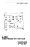
Chime
CO Input
Unlock
Door
Power
Intercom
Phones
Ring
3/5 rng
1
2
3
#
*NoorCO
Strike
Active
12VAC
Intercom
Active
Strike
Time
Model
P-0920
CHANNEL
V ISION
TM
LLER
TELEPHONE ENTRY CONTRO
Telephones
CO Input
P-0920
Telephone Entry Controller
• Intelligent Entertainment • Infrastructure • Security Solutions
The P-0920 is a telephone entry controller that works with Channel
Vision’s IU and DP series door stations to create an elegant door
intercom system. When the door station button is pressed, the phones
will ring. Simply answer the phone and you will be able to speak to the
person at the door.
Features:
! Distinctive telephone ring
! LED status indicators
! RJ-45 connections for input and output
Phone line in from the service provider CO (Central Office).
Dry contact that closes when the doorbell button is pressed.
Connect a standard push-button. When the button is pressed
the door strike relay will be activated.
Note: TE110DS is sold separately.
Connect a compatible door intercom station.
Orange Terminal - Connect 12VAC power supply
Output to telephones.
WARNING!
Power should only be applied to
the orange power terminal.
If power is applied to other inputs,
the resulting damage is not covered
under warranty.
CO Input
Chime
Unlock
Door
Intercom
Power
Phones
Ring
Strike
Active
or #
No CO
3/5 rng
1
2
3
*
12VAC
Intercom
Active
Strike
Time
Model
P-0920
PRO
CHANNEL
V ISION
TM
TELEPHONE ENTRY CONTROLLER
CO Input
2
Telephones
Ring LED
Flashes when phones ring.
Intercom Active LED
Lights when door
intercom station is in use.
Strike Active LED
Lights when the door
strike relay has been
activated.
Configuration switches
(see basic setup).
RJ-45 input for CO lines and output to Telephones.
These allow pass-through of 4 telephone lines.
Note: only line 1 is affected by the telephone entry controller.
Important: The RJ-45 input and output cannot be used if
there is a CO line connected to the wire terminal input.
Compatibility
The P-0920 must be used together with a compatible door intercom
station. Channel Vision offers a variety of compatible units such as the
popular IU-series and DP-series intercom stations. Example: model DP0212 is compatible.
Important Exceptions:
Channel Vision offers some IU-series and DP-series intercom stations
that are only compatible with Panasonic KSU phone systems. These
model numbers, which end with the letter “P”, will NOT WORK.
Example: model DP-0212P is NOT COMPATIBLE.
How it Works
The P-0920 is installed in-line between your telephone service provider
and your telephone distribution system. A compatible door intercom
station is installed and connected to the P-0920. When the door
intercom’s button is pressed, the phones in the house will ring. If the
phone is answered within 20 seconds you will be automatically connected
to door intercom station. If you wish to contact the door intercom station
after 20 seconds has passed, pick up the phone and dial ** (or ##
depending your configuration).
If you are using the optional TE110DS door strike relay module, it can be
activated by dialing the appropriate touch-tone code (see the user’s guide
section) or by pressing a button that is connected to the “Unlock Door”
terminals. You can use the “Unlock Door” terminals If you would like to
open an access gate from outside of the house without using a
telephone. Simply wire a standard push button to these terminals that will
provide a momentary short when the button is pressed.
Use the “Chime” terminals if you would like to use a traditional doorbell
chime in addition to ringing the telephones when the door intercom button
is pressed.
Wiring Options
For convenience, there are two different ways to connect the active
phone line input and telephone output.
Option 1: connect the active phone using a single pair of wires to the wire
terminals labeled “CO Input”. Then connect a single pair of wires to the
wire terminals labeled “Telephone” and connect the other end of those
wires to your telephone distribution wiring system.
Option 2: use the RJ-45 jacks to connect the “CO Input” and “Telephone”
output. This option simplifies wiring because CAT5 jumper cables can be
used to interconnect the P-0920 with other Channel Vision telephone
modules.
3
Basic Application
For proper operation, the system must be connected as shown. If
telephones are connected directly to the telephone service provider, those
telephones will not be able to utilize the entry system.
This system uses a 12 Volt AC power supply. Make sure you use the
power supply provided with the unit (or an equivalent replacement). If a
DC power supply is used, the system may appear to work normally, but it
will not be able to ring the phones.
The configuration switches affect many of the P-0920’s features. Use the
guide below to configure the P-0920 for your application.
From Telephone
Service Provider
12VAC
500mA
CO Input
Chime
Unlock
Door
Intercom
Power
Connect to the
terminals marked
“TO SYS”
Phones
Ring
Strike
Active
Intercom
Active
or #
No CO
3/5 rng
1
2
3
*
12VAC
Strike
Time
Model
P-0920
PRO
CHANNEL
V ISION
TM
Door Plate
(IU-xxxx or DP-xxxx)
TELEPHONE ENTRY CONTROLLER
Telephones
CO Input
Key * - #: Sets the activation key for the P-0920. On = #, Off = *
On
No CO-on: Enables “No CO” mode, allowing the unit to work if there is no
active telephone line.
*
or #
No CO
3/5 rng
1
2
3
Off
4
House
Telephones
Strike
Time
Rings 3-5: Sets the ring pattern. On = 5 rings, Off = 3 rings.
Strike Time: Sets the length of time the TE110DS will be activated. See the
chart below.
3
1 2
3
1 2
Off Off On
20 Seconds
Off Off Off
3 Seconds
On Off On
40 Seconds
On Off Off
5 Seconds
Off On On 120 Seconds
Off On Off
8 Seconds
On On On 240 Seconds
On On Off
15 Seconds
Using the TE110DS
Door Strike Relay
TE110DS is a normally open dry contact. It can be activated from your
telephone by pressing a sequence of keys on your touch tone phone.
When activated, the contact closes, allowing power to be delivered to the
electronic door opener (or strike). The contact will remain closed for the
duration set by the “Strike Time” configuration switches as shown in the
“Basic Application” diagram.
Simple push button (optional)
From Telephone
Service Provider
TE110DS
(Sold Separately)
12VAC
500mA
CO Input
Chime
Unlock
Door
Intercom
Power
Phones
Ring
-
or #
No CO
3/5 rng
1
2
3
*
12VAC
Intercom
Active
Model
P-0920
Negative
Strike
Active
Strike
Time
PRO
CHANNEL
V ISION
TM
Strike
Power
Supply
TELEPHONE ENTRY CONTROLLER
CO Input
-
Telephones
Negative
+
Positive
Door strike
Mechanism
(NOT SOLD BY CHANNEL VISION)
House
Telephones
Door Plate
(IU-xxxx or DP-xxxx)
5
Basic DSL Filtering for TE110 system
TELCO
Demarcation
Block
Phone Line
with Data
DSL
Modem
DSL
Filter
Voice Line Only
12VAC
500mA
CO Input
Chime
Unlock
Door
Intercom
Power
Phones
Ring
Strike
Active
or #
No CO
3/5 rng
1
2
3
*
12VAC
Intercom
Active
Strike
Time
Model
P-0920
PRO
CHANNEL
V ISION
Door Plate
(IU-xxxx or DP-xxxx)
TM
TELEPHONE ENTRY CONTROLLER
CO Input
6
Telephones
House
Telephones
Filtering DSL Using the P-0411
From TELCO
Demarcation
To Phones
o
From Telc
CO Lines
1
2
DSL
Modem
3
4
Ring
PRO
Model
P-0411
EL
CHANN
V ISION
TM
/ Surge
ADSL Filter
Suppressor
tem
Security sys mal
Nor
Bypass
To Phones
From Telco
DSL Modem
TIA568A
RJ-31x
TIA568A
DSL filter is only on line 1
(Blue/Blue White pair)
12VAC
500mA
CO Input
Chime
Unlock
Door
Intercom
Power
Phones
Ring
Strike
Active
Intercom
Active
or #
No CO
3/5 rng
1
2
3
*
12VAC
Strike
Time
Model
P-0920
PRO
CHANNEL
V ISION
TM
Door Plate
(IU-xxxx or DP-xxxx)
TELEPHONE ENTRY CONTROLLER
CO Input
Telephones
House
Telephones
7
Using a traditional Door Chime
If you would like the P-0920 to ring the phones and a traditional doorbell
chime, this can be easily done by following the diagram below. The wire
terminals labeled “Chime” are simply dry contacts that close whenever the
button on the door intercom is pressed. Wire any standard door chime to
these wire terminals as if the wire terminals were the actual doorbell
button. When the door intercom button is pressed these wire terminals will
short together and your doorbell chime will ring.
Doorbell
Chime
Doorbell
Transformer
Doorbell
power
supply or
AC power
From
Telephone
Service
Provider
DO NOT PLUG POWER SUPPLY INTO INTERCOM
12VAC
500mA
CO Input
Chime
Unlock
Door
Intercom
Power
Phones
Ring
Strike
Active
Intercom
Active
or #
No CO
3/5 rng
1
2
3
*
12VAC
Strike
Time
Model
P-0920
PRO
CHANNEL
V ISION
Door Plate
(IU-xxxx or DP-xxxx)
TM
TELEPHONE ENTRY CONTROLLER
CO Input
8
Telephones
House
Telephones
User’s Guide
Basic Configuration:
Note: see the basic application page for details on switch settings.
Set the switch labeled “Key # - *” to determine which key will activate the
system.
Set the switch labeled “No CO” for the desired mode.
Set the switch labeled “Rings 3-5” to the desired distinctive ring pattern.
You can choose between a 3-ring or 5-ring pattern.
Set the switches labeled “Strike Time” to allow an electronic door release
to be activated for a specific period of time.
Basic Operation:
Note: The following instructions assume that the “Key * - #” switch is set
for “*” operation.
When the doorbell button is pressed, you will hear the distinctive ring
pattern selected above:
within 20 seconds - simply pick up the telephone to be connected to the
door speaker.
after 20 seconds - pick up the telephone and press “**” to be connected to
the door speaker.
To end communication with the door speaker, you can hang up the phone
or press “**”.
If you are already on the phone when the doorbell button is pressed you
will hear a call waiting tone. Simply press “**” to put your call on hold
while you are connected to the door speaker. Press “ **” to return to
your call.
To close the door strike relay while you are already communicating with
the door speaker, press “*7”.
To close the door strike relay when you are not communicating with the
door speaker, press “***7”.
To close the door strike relay without using a phone, you can use an
optional push button wired to the “Unlock Door” terminals (see “Using
the TE110DS Door Strike Relay” for details).
9
Connection Tips and Troubleshooting
1) When the doorbell is pressed the phones do not ring, but you
can activate and speak to the door station by pressing ** (or ##
depending on setup).
a. Make sure that you have the correct power supply and that it is
supplying 12 VAC.
b. Measure the AC voltage on the “Phones” terminals at the time
when the unit should be ringing (just after the doorbell button is
pressed). There should be between 70 - 90 VAC across the
terminals during a ring cycle.
2) The phones in the house cannot communicate with the door
station.
a. Make sure the power supply is plugged in.
b. Make sure the phones are connected to the output labeled
“Phones” on the telephone entry controller. To test unit, connect
one phone directly to the “Phones” wire terminals.
3) A static or “screeching” noise is heard when speaking to the
door station.
a. If DSL is present in the system, install a DSL filter on the phone
line before the telephone entry controller.
4) The phone does not release the line when it is hung up after
speaking to the door station.
a. This occurs when the phones in use draw unusual amounts of
current and the telephone entry controller cannot sense the
change. To disconnect, press the disconnect key (this could be
either ## or ** depending on setup).
5) The TE110DS does not activate.
a. Make sure you’re pressing the correct key sequence.
If already speaking to the door station, just press *7 (or #7).
If not already speaking to the door station, press ***7 (or ###7).
b. Measure the voltage on the wire terminals labeled “INTERCOM”
When the system is idle, there should be 1 VDC on the terminals.
When speaking to the door station, there should be approximately
6 VDC on the terminals.
When the TE110DS is activated there should be at least 10 VDC
on the terminals.
10
Stripping and Connecting CAT5 Wire
CAT5 cable should be stripped with a proper stripping tool, such as Channel
Vision’s J-110 tool.
1. Place the CAT5 between the blade and the first notch of the J-110 tool.
Blade
CAT5
2. Rotate the tool only once. Multiple
turns could damage the inner wires.
3. Inspect the inner wires for damage.
If any wires are cut start over at step 1.
Check for damage
Rotate
1 turn only
Slight
pressure
TIA-568A RJ-45 Modular Plug
Side view:
Top view:
Green/White
Green
Orange/White
Blue
Blue/White
Orange
Brown/White
Brown
Specifications: (typical @25º C)
Power Supply:
12VAC, 500mA
Cable Requirements:
CAT5 or better
REN:
0.1
Ring Output:
>5 (capable of ringing >10 phones with a REN of 0.5)
Dimensions:
6.5” x 5.5” x 1.5”
Operating Temperature:
-10ºC to +50ºC
Specifications subject to change without notice.
11
1
Channel Vision Technology will repair or replace any defect in material
or workmanship which occurs during normal use of this product with
new or rebuilt parts, free of charge in the USA, for one year from the
date of original purchase. This is a no hassle warranty with no mail in
warranty card needed. This warranty does not cover damages in
shipment, failures caused by other products not supplied by Channel
Vision Technology, or failures due to accident, acts of God, misuse,
abuse, or alteration of the equipment. This warranty is extended only to
the original purchaser when purchased through an authorized reseller.
A purchase receipt, invoice, or other proof of original purchase date will
be required before warranty repairs are provided.
Mail in service can be obtained during the warranty period by calling
(714) 424-6500. A Return Authorization number must be obtained in
advance and can be marked on the outside of the shipping carton.
This warranty gives you specific legal rights and you may have other
rights (which vary from state to state). If a problem with this product
develops during or after the warranty period, please contact Channel
Vision Technology, your dealer or any factory-authorized service center.
Channel Vision products are not intended for use in medical, lifesaving,
life sustaining or critical environment applications. Channel Vision
customers using or selling Channel Vision products for use in such
applications do so at their own risk and agree to fully indemnify Channel
Vision for any damages resulting from such improper use or sale.
Tested To Comply
With FCC Standards
This device complies with part 15 of the FCC rules. Operation is subject to
the following two conditions: (1) This device may not cause harmful
interference, and (2) This device must accept any interference received,
including interference that may cause undesired operation.
• Intelligent Entertainment • Infrastructure • Security Solutions
234 Fischer Avenue, Costa Mesa, California 92626 USA
(714)424-6500 (800)840-0288 (714)424-6510 fax
email: [email protected]
www.channelvision.com
500-142 rev G