1
C HANNEL V ISION
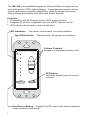
Pwr
Source
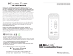
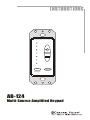
AB-124
Multi-Source Amplified Keypad
10
The AB-124 is an amplified keypad for Channel Vision’s single-source
and multi-source CAT5 audio systems. It provides convenient volume
control and source selection capabilities, while its elegant decorator
styling blends seamlessly with other wall switch devices.
Features:
! Compatible with all Channel Vision CAT5 audio systems
! Supports IR control: compatible with the A0501 remote control
! LEDs show volume level or source selection
LED Indicators ... Can show volume level or source selection.
Top LED Indicator ... Flashes when IR signals are received.
C HANNEL V ISION
Volume Controls...
Increase or decrease volume level.
IR Window...
Receives signals from IR remote
controls.
Pwr
Source
Pwr/Source Button ... Keypad On/Off control and source selection
control when in multi-mode.
2
Compatibility
The AB-124 adheres to the same protocols as Channel Vision’s other CAT5
audio hubs to ensure maximum compatibility. However, when using the AB124 in a multi-source system, we recommend using Channel Vision’s multisource CAT5 audio matrix (model P-1044). Multi-source CAT5 audio products
from other manufacturers may not (and typically will not) use the same control
codes for advanced features such as source selection.
How it Works
The AB-124 can be used in two different modes: 1) single source mode, 2)
multi-source mode. Mode selection is controlled by a jumper setting prior to
installation. When using the AB-124 with a single-source CAT5 audio hub, it
should be set for the single-source mode. In this mode, the unit provides basic
controls: volume up, volume down, and power on/off. When using it with a
multi-source CAT5 aduio matrix, it should be set for multi-source mode. In this
mode, any zone can independently select and listen to any source at any time.
Source selection can be done either from the AB-124 amplified keypad or by
using the A0501 remote control.
Basic Operation
Using the AB-124 Amplified keypad...
The Pwr (power) button located at the lower left of the keypad is used for
source selection and to turn the unit on or off. When in single-source mode,
press and release the Pwr button to toggle the keypad on or off. When in
multi-source mode, if the keypad is off, press and release Pwr to turn it on.
Press Pwr again to see the current source selection and press repeatedly to
scroll through the 4 sources. Press and hold the power button to turn the
keypad off. While the keypad is off, press and hold the power button again to
turn off the zone output of the P-1044.
As you change sources when in multi-mode, you’ll notice that the top 4 LEDs
illuminate corresponding to the source you have selected. When source one
is selected, the first LED is illuminated, when source two is selected, the
second LED is illuminated, and so on.
After a source is selected the LED will stay lit for 5
seconds, then it will return to showing the current
volume level.
Volume adjustments can be made using the
up/down buttons to the right hand side of the
keypad. The keypad can be controlled from the
A0501 remote control (see the section titled: Using
the A0501 remote control for more details).
These four LEDs illuminate to indicate
which source input is selected.
! The Pwr button is used for source selection.
!
C HANNEL V ISION
{
Pwr
Source
3
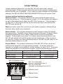
Jumper Settings
Jumper settings determine how the AB-124 will react under various
circumstances. These jumpers should be set to the desired configuration
before the AB-124 is installed. If you need to make changes to the jumper
settings, the AB-124 MUST BE DISCONNECTED from the system first.
Jumper setting functions explained:
Volume Preset - This jumper determines how loud the keypad will be
when it is turned on. If the jumper is on pins 1 & 2, the volume will always
be set at the default level when the AB-124 is turned on. If the jumper is
on pins 2 & 3, the volume will be at the same level as it was before the
AB-124 was turned off.
Status is active when the zone is on and audio is present. Status will go
dormant when audio is not present.
Status Active - This jumper determines what happens when the status
becomes active. Typically, when status becomes dormant, Channel Vision
amplified keypads go into a ‘sleep’ mode which mutes the amplified
keypad. If the jumper is on pins 1 & 2 when status becomes active, the
AB-124 will remain off until the power button is pressed. If the jumper is
on pins 2 & 3 when the status becomes active, the AB-124 will return to its
previous state (either on or off).
Source Mode - This jumper determines if the AB-124 will be used as a
multi-source keypad or a single-source keypad. If you are using the
keypad in a single source system, set the jumper on pins 1 & 2. If you are
using the keypad in a multi-source system, set the jumper on pins 2 & 3.
Jumper Function
Jumper on Pins 1 & 2 Jumper on Pins 2 & 3
Volume Level
Status Active
Default volume level
Off until Pwr is pressed
Previous volume level
Source Mode
Single-Source
Multi-Source
Previous state
AB-124 (Bottom View)
Pin 1 is to the right
(arrow is pointing at pin 1)
Pin 3 is to the left
(Jumper is covering Pins 2 & 3)
Volume Level
Status Active
Source Mode
4
Installation
AB-124 (Rear View)
Balance ... The two potentiometers on the AB-124
adjust the volume levels of each speaker channel. Use
these to adjust the speaker balance in this zone.
Gasket ... The AB-124 is shipped with
a gasket. This allows you to adjust the
height and fit of a decorator trim plate.
Leave the gasket as is for a flush fit.
Remove the gasket to have the AB-124
stand above the plate.
C HANNEL V ISION
Connectors ... To simplify installation,
the AB-124 has both 110 and RJ-45
inputs. Only one of the inputs should
be used at a time.
Pwr
Source
AB-124 (Side View)
Connect the AB-124 as shown.
Link In
Zone 1
Zone 3
Active
Active
Zone 2
Zone 4
Active
Active
Model
P-1044
Source 1 IR
Source 2 IR
Link Out
PRO
CHANNEL
V ISION
TM
Source 3 IR
Source 4 IR
Common IR
IR Data
Power
Source 1
Source 2
Source 3
Source 4
+24VDC
P-1044 CAT5 Audio Matrix
5
Single-Source System
When using the AB-124 with single-source CAT5 audio hubs, the source
mode jumper should be set for single-source. In this mode, the source
selection features are not available. Pressing the Pwr button will turn off
the keypad, but other keypads will continue to play.
AB-124
C HANNEL V ISION
C HANNEL V ISION
C HANNEL V ISION
Pwr
Source
Pwr
Source
Pwr
Source
C HANNEL V ISION
Model
P-1014
System
Input
Pwr
Source
Zone 1
Zone 2
3
IR
Status
+12VDC
Power
+24VDC
9
2
6
5A
1 x 4 CAT
le
odu
ution M
trib
udio Dis
System
ion
Expans
Output
Zone 4
Zone 3
1
5
Signal
Local
Po
we
r
7
0
4
8
Priority
L
Local
Input
R
Integrated IR repeating
allows source to be
controlled from any room.
P-1014
CD player
6
Emitters
(Optional) IR emitters
AB-T2454
power supply
(included)
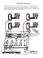
Multi-Source Application
When using the AB-124 in a multi-source system with the P-1044, the
source mode jumper should be set for multi-source. In this mode, the
source selection features are enabled allowing any zone to independently
select and listen to any source at any time.
AB-124
C HANNEL V ISION
C HANNEL V ISION
Pwr
Source
Pwr
Source
C HANNEL V ISION
C HANNEL V ISION
Pwr
Source
Po
we
r
7
0
4
8
1
5
9
2
6
3
Pwr
Source
Link In
Zone 1
Zone 3
Active
Active
Zone 2
Zone 4
Active
Active
Model
P-1044
Source 1 IR
Source 2 IR
Integrated IR repeating
allows sources to be
controlled from any
room.
Link Out
PRO
CHANNEL
V ISION
TM
Source 3 IR
Source 4 IR
Common IR
IR Data
Power
Source 1
Source 2
Source 3
Source 4
+24VDC
P-1044
Sat radio
CD player
(Optional) IR emitters
AB-T2454
power supply
(included)
7
Using the A0501 remote control
The A0501 is designed to allow you to control your P-1044 without having to
touch the buttons on the AB-124. Simply point the A0501 remote control at the
IR sensor located at the bottom of the AB-124 and press the desired button.
Zone Power - Turns on/off the zone output of the P-1044.
Power - Turns on/off the AB-124.
C HANNEL V ISION
POWER
MODEL
A0501
1
S
O
U
R
C
E
2
3
4
ZONE
POWER
C HANNEL V ISION
TM
LED indicators
on the AB-124
will light when
source buttons
are pressed on
the A0501.
Pwr
Source
MUTE
VOL
C HANNEL V ISION
TM
POWER
MODEL
A0501
VOL - Controls volume
for the keypad
1
S
O
U
R
C
E
2
3
4
ZONE
POWER
MUTE
VOL
Downloading IR commands...
If you don’t have access to the A0501 remote and you need to program a
learning remote, you can download the IR codes from the internet. IR codes
compatible with the Philips Pronto remote controls can be downloaded from
the following websites:
www.channelvision.com (codes in Hex format)
www.remotecentral.com (codes in Pronto format)
8
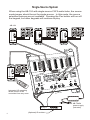
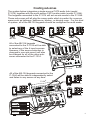
Creating sub-zones
The system below integrates a single-source CAT5 audio hub (model
P-1014) together with the multi-source CAT5 audio matrix (model P-1044).
The keypads connected to the P-1014 will act as sub-zones to the P-1044.
These sub-zones will all play the same audio which is perfect for common
areas such as hallways, bathrooms, kitchen, or dinning room. For this kind
of system, all of the AB-124 keypads should be configured for multi-mode.
C HANNEL V ISION
C HANNEL V ISION
C HANNEL V ISION
Hallway
Pwr
Source
Pwr
Source
C HANNEL V ISION
Dining Room
Pwr
Source
Bathroom
Kitchen
Pwr
Source
AB-124
All of the AB-124 keypads
connected to the P-1014 will be able
to select any of the 4 input sources.
However, if the source selection is
changed in one sub-zone it will also
be changed for all of the other subzones connected to the P-1014.
Model
P-1014
System
Input
System
Priority
L
T5 Audio
1 x 4 CA
Signal
on
Distributi
ion
Expans
Output
Zone 4
Zone 3
Zone 2
Zone 1
Module
IR
Status
+12VDC
Power
+24VDC
Emitters
Local
Local
Input
R
P-1014
All of the AB-124 keypads connected to the
P-1044 will be able to independently select
and listen to any source at any time.
C HANNEL V ISION
P-1044
Pwr
Source
Bedroom 2
ne 3
Active
ne 1
C HANNEL V ISION
Active
ne 4
C HANNEL V ISION
k Out
Active
ne 2
Active
Pwr
Source
Bedroom 1
Link In
PR O
EL
Model
P-1044
CHANN
V I S ION
TM
Pwr
Source
IR
Source 4
IR
Source 3
Common
IR
Bedroom 3
IR Data
IR
Source 2
IR
Source 1
Power
Source 4
+24VDC
Source 3
Source 2
Source 1
Sat radio
DVD player
CD player
AM/FM radio
9
Connection Tips and Troubleshooting
1) Be sure you have connected the CAT5 cable correctly. Follow the TIA568A standard at both ends. Mis-wiring can cause distorted sound or
prevent the system from working at all!
2) Be sure you have connected the speakers in phase. Follow the label
on the product. Out of phase speakers can rob the system of its bass,
especially when driving dual-voice-coil speakers.
3) Trouble with IR control?
a. Make sure you are using the correct remote control. The AB-124
will respond to IR signals from the A0501 and the AB-500 remotes
produced by Channel Vision. The A0501 can provide both volume
control and source selection commands, but the AB-500 is only
pre-programmed with the volume control commands. Other 3rd
party remote controls that are capable of learning the IR codes
from the A0501 can also be used.
b. The top LED on the AB-124 acts as an IR receiver feedback LED
that flashes whenever IR signals are received. Check to make
sure the LED flashes whenever you press buttons on your remote
control. If you don’t see the feedback LED, try replacing the
batteries in your remote control.
c. Make sure your IR emitters are placed directly over the sensor on
the device you are trying to control.
4) If no audio is heard, check to make sure that the audio source is
playing, then press the power button on the AB-124 to make sure it is
turned on.
a. Note, if the status jumper is on pins 1 & 2, the AB-124 will turn off if
there is no audio present for more than 2 minutes. For most
applications, it will be desirable to place the status jumper on pins 2
& 3 so that the AB-124 will revert back to its previous condition
(either on or off) when music is played after a long pause.
b. There may be something wrong with the CAT5 audio hub. Some
Channel Vision audio hubs provide LED indicators to show which
zones are connected and active. Review these LEDs and refer to
the instruction manual for your specific audio hub.
5) Observe wiring distance specifications. The maximum recommended
wire length between the audio hub output and AB-124 is 150 feet.
Although the AB-124 can work at greater distances, such extreme
distances are not recommended because erratic performance may
result due to the power loss caused by the CAT5 wire.
6) If you need additional help troubleshooting the AB-124 please contact
Channel Vision technical support (1-800-840-0288) or check our
website for more details: www.channelvision.com.
10
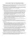
Stripping and Connecting CAT5 Wire
CAT5 cable should be stripped with a proper stripping tool, such as Channel
Vision’s J-110 tool.
1. Place the CAT5 between the blade and the first notch of the J-110 tool.
Blade
Cat5
2. Rotate the tool only once. Multiple
turns will cause you to cut into the
inner wires.
Rotate
1 turn only
3. Inspect the inner wires for damage.
If any wires are cut start over at step 1.
Slight
pressure
Check for damage
TIA-568A RJ-45 Modular Plug
Side view:
Green/White
Green
Orange/White
Blue
Blue/White
Orange
Brown/White
Brown
Top view:
Specifications: (typical @25º C)
Operating Voltage :
Cable requirements:
Speaker impedance:
IR repeating:
IR sensor range:
Operating Temperature:
24VDC
CAT5 or better
6-8 ohm
30-60kHz
40’@40kHz, 25’@56kHz
-10ºC to +50ºC
Specifications subject to change without notice.
11
1
Channel Vision Technology will repair or replace any defect in
material or workmanship which occurs during normal use of this
product with new or rebuilt parts, free of charge in the USA, for one
year from the date of original purchase. This is a no hassle warranty
with no mail in warranty card needed. This warranty does not cover
damages in shipment, failures caused by other products not supplied
by Channel Vision Technology, or failures due to accident, misuse,
abuse, or alteration of the equipment. This warranty is extended only
to the original purchaser, and a purchase receipt, invoice, or other
proof of original purchase date will be required before warranty
repairs are provided.
Mail in service can be obtained during the warranty period by calling
(800) 840-0288 toll free. A Return Authorization number must be
obtained in advance and can be marked on the outside of the shipping
carton.
This warranty gives you specific legal rights and you may have other
rights (which vary from state to state). If a problem with this product
develops during or after the warranty period, please contact Channel
Vision Technology, your dealer or any factory-authorized service
center.
Channel Vision products are not intended for use in medical,
lifesaving, life sustaining or critical environment applications.
Channel Vision customers using or selling Channel Vision products
for use in such applications do so at their own risk and agree to fully
indemnify Channel Vision for any damages resulting from such
improper use or sale.
500-128 revC