1
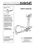
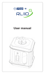
Rugby 55 User Manual Version 1.0 English Introduction Congratulations on the purchase of a new Rotating Laser product. Product The Rugby 55 is a laser tool for interior, general construction and other leveling applications. It is engineered and built with the latest innovations in the laser tool industry. It is designed to be easy to set up, simple to operate and highly dependable. This manual contains important safety directions as well as instructions for setting up the product and operating it. Refer to "9 Safety Directions" for further information. Read carefully through the User Manual before you switch on the product. Product Identification The model and the serial number of your product are indicated on the type plate. Enter the model and serial number in your manual and always refer to this information when you need to contact your agency or Leica Geosystems authorized service workshop. Type: _______________ Serial No.: _______________ Rugby 55 II Symbols The symbols used in this manual have the following meanings: Type Warning Danger Caution ) Trademarks Description Indicates an imminently hazardous situation which, if not avoided, will result in death or serious injury. Indicates a potentially hazardous situation or an unintended use which, if not avoided, could result in death or serious injury. Indicates a potentially hazardous situation or an unintended use which, if not avoided, may result in minor or moderate injury and/or appreciable material, financial and environmental damage. Important paragraphs which must be adhered to in practice as they enable the product to be used in a technically correct and efficient manner. All trademarks are the property of their respective owners. Rugby 55 III Table of Contents In this manual Chapter Page 1 Description of the System .......................................................1-1 2 Basic Operation .......................................................................2-1 3 Accessories ..............................................................................3-1 4 Applications .............................................................................4-1 5 Batteries ..................................................................................5-1 6 Accuracy Adjustment ...............................................................6-1 7 Troubleshooting.......................................................................7-1 8 Care and Transport ..................................................................8-1 9 Safety Directions .....................................................................9-1 10 Technical Data .......................................................................10-1 Index .................................................................................................i-1 Rugby 55 IV 1 Description of the System 1.1 Features Precision Designed to maintain its accuracy on the toughest of jobs, the Rugby 55 projects a rotating beam usable up to 150 meters (500 feet) with a receiver. Simplicity The Rugby 55 is designed to be versatile, easy to operate and having features that serve both the interior and general construction contractor well. A bright, visible beam, variable head speed, scanning motion, horizontal and vertical self-leveling, split beam and great battery life, combine to provide consistent value for the professional contractor. Ruggedness Engineered for construction environment, the Rugby 55 will provide reliable performance day after day. Description of the System Rugby 55 1-1 1.2 Rugby Components a b e c f d g a) b) c) d) e) f) g) Description of the System Window assembly and rotating head Membrane switch panel Battery door and locking knob Charge port with LED (rechargeable models) Carrying handle (on back) 5/8”-11 mounting holes (on back and bottom) Positioning guides Rugby 55 1-2 1.3 Rugby 55 Membrane Switch Panel a e b f c d g a) b) c) d) e) f) g) Description of the System Low Battery LED Left / Right Positioning Buttons Scanning Button Head Speed Button (rps) X/Y Axis Level Indication LED’s Power Button CW / CCW Arrow Buttons Rugby 55 1-3 1.4 Case Component Locator, Interior Case b f g c h a d i e a) b) c) d) e) f) g) h) i) Description of the System Wall mount bracket Spare battery holder Alkaline batteries Remote control Ceiling grid targets User manual Receiver Rugby 55 Accessories compartment Rugby 55 1-4 1.5 Case Component Locator, Standard Case a b f e c d a) b) c) d) e) f) Description of the System User manual Accessories and second receiver Spare batteries, D-cells Spare battery pack, NiMH Receiver Rugby Rugby 55 1-5 2 Basic Operation In this chapter Topic 2.1 2.2 2.3 2.4 2.5 2.6 Basic Operation Page Introduction ........................................................................2-2 The LED Indicators ..............................................................2-3 The Switch Buttons .............................................................2-4 Special Features ..................................................................2-6 Manual Mode with cross axis self-leveling ..........................2-9 The Elevation Alert (H.I.) Function ....................................2-12 Rugby 55 2-1 2.1 Introduction The Rugby 55 is easy to understand and simple to use. The descriptions of the LED’s and Switch Buttons that follow will explain their basic functions. The Rugby 55 is designed to serve you in a variety of applications. Developed specifically for the interior contractor. the Rugby 55 can also be used together with a laser receiver for many outdoor, general construction applications. This manual contains operating and set-up procedures for common applications. Its purpose is to describe the features of the Rugby 55 and how it operates. This manual is not intended to describe specific applications. Contact Leica Geosystems or your distributor for information specific to your jobsite requirements. Basic Operation Rugby 55 2-2 2.2 The LED Indicators The LED Indicators have three main functions • To indicate the level status of the axes. • To indicate the battery status. • To indicate an H.I. Alert condition. Additional functions will be described for specific conditions later in this manual. (a) Y X H.I. (b) X and Y Indicators (a) - Indicate the level status. • • • • Green - Indicates the axis is level. Green Flashing - Indicates the axis is leveling. Red - Indicates the axis is in Manual mode. Both Flashing Red - Indicates an H.I. Alert condition (if H.I. is enabled). Low Battery Indicator (b) When the LED is off, the battery is still good. When it is flashing slowly the battery is getting low. When the LED begins to flash rapidly it is time to change the batteries. Basic Operation Rugby 55 2-3 2.3 The Switch Buttons Off / On Power Button • Press to turn the Rugby On and Off Head Speed Button • Press to change the speed of the head rotation - 0 • 2 • 5 • 10 rps Scan Mode Button • Press to change the width of the scanning beam - 10° • 45° • 90° • 180° Automatic / Manual Mode Button • Press to change the Y-axis to manual mode • with X-axis self-leveling • Press again to change the X-axis to manual mode • with Y-axis self-leveling • Press again to change both axes to manual mode • with no self-leveling • Press again to change back to full automatic mode. Note the changes in the LED indicators in these manual modes. The red LED indicates that the axis is in manual mode. Basic Operation Rugby 55 2-4 Clockwise and Counter-Clockwise Buttons (CW & CCW) • Press to rotate the stationary and scanning beam in a CW or CCW motion Manual Mode, Slope and Layout Buttons • • Basic Operation Press to tilt the axis that is set to manual mode In the laydown position, press to align the rotating and 90° split beam Rugby 55 2-5 2.4 Special Features Beam Down • Press the Head Speed Button to stop the rotating head (zero rps). The position of the beam will automatically move to the “downward” position to allow the user to align the Rugby over a reference point on the floor. Changing to 0-rps, positions the beam in the plumb down position. Basic Operation Rugby 55 2-6 Scan-90 and Scan-Memory + • Press and hold either the CW or CCW button, then press the Scan or Head Speed Button to quickly move the scanning or stationary beam at 90° intervals. In scan mode, the scan width will automatically change to the smallest scan width when this function is activated. • For layout work, use the Beam Down feature (a) to position the beam over a reference point. Then, use the Scan-90 feature (b) to quickly move the small scan to a position to the left or right of the laser. For ceiling applications and marking elevations, the Scan-90 feature can quickly bring the scanning beam to you. Scan Memory means that you can switch to rotational or stationary mode and the scan will return to the previous position wheh scanning motion is again chosen. + • b • a Basic Operation Rugby 55 2-7 Sleep Mode + • Press both the Up and Down buttons simultaneously on the Remote to put the Rugby 55 into Sleep Mode. • • During Sleep Mode all functions are disabled. The Low battery indicator will flash once every ten seconds to indicate that the unit is in sleep mode. The Rugby will sleep for up to two hours, then will shut off automatically and must be turned on again at the laser. When in Sleep Mode, pressing any key will wake the unit and normal operation will resume. • • Basic Operation Rugby 55 2-8 2.5 Manual Mode with cross axis self-leveling The Rugby is designed to always start up in automatic mode * *) It may be desirable to save a manual setup. The automatic mode on start up can be disabled using a special procedure found in the Troubleshooting section. Press the Auto/Manual Button once to change the Y-axis to manual mode • Y X H.I. • • • The Y-axis will not self-level and slope can be entered in this axis using the arrow buttons on the Rugby or the remote control. The X-axis will continue to self-level. The Y-axis LED will be red. The X-axis LED will blink green until level. When the Y-axis is in manual mode, the Y-axis can be sloped as illustrated here. The X and Y axes are marked on the top of the Rugby. Basic Operation Rugby 55 2-9 Press the Auto/Manual Button again to change the X-axis to manual mode • X H.I. Y • • • The X-axis will not self-level and slope can be entered in this axis using the arrow buttons on the Rugby or the remote control. The X-axis LED will be red The Y-axis will continue to self-level The Y-axis LED will blink green until level. When the X-axis is in manual mode, the X-axis can be sloped as illustrated here. The X and Y axes are marked on the top of the Rugby. Basic Operation Rugby 55 2-10 Press the Auto/Manual Button again to change to full manual mode • Y X H.I. • • Both the X-axis and Y-axis will not self-level and slope can be entered in either or both axes using the arrow buttons on the Rugby (Y-axis) or the remote control (either axis). The X-axis LED will be red. The Y-axis LED will be red. When both the X and Y axes are in manual mode, both axes can be sloped as illustrated here. The X and Y axes are marked on the top of the Rugby. Basic Operation Rugby 55 2-11 2.6 The Elevation Alert (H.I.) Function • Y X H.I. • • • ) Basic Operation The Elevation Alert or Height of Instrument function is designed to prevent incorrect work caused by sudden movement or settling of the tripod that would cause the laser to level at a lower height. The Elevation Alert function becomes active and monitors the movement of the laser 30 second after the unit has completely leveled and the head starts rotating. The elevation alert monitors the laser and both the X and Y axis LED’s will begin flashing and the Rugby will beep rapidly if disturbed. To stop the alert turn Rugby off and on again. Check the height of the instrument before beginning to work again. The elevation alert feature of the Rugby 55 is normally OFF when shipped. It can be enabled to turn on automatically every time the Rugby is turned on by using a special procedure found in the Troubleshooting section. Rugby 55 2-12 3 Accessories In this chapter Topic 3.1 3.2 3.3 3.4 Accessories Page The The The The IR Remote Control ........................................................3-2 Wall Mount ...................................................................3-4 Ceiling Grid Target ........................................................3-5 Batter Board Clamp ......................................................3-6 Rugby 55 3-1 3.1 The IR Remote Control ) The IR Remote Control communicates with the Rugby via infrared signals, and is used to control the same functions as on the laser. (a) a) CW and CCW Buttons Press to rotate the stationary and scanning beam in a CW or CCW motion. (b) b) Left and Right Buttons Press to tilt the Y-axis when it is manual mode. In the laydown position, press to align the rotating and 90° split beam. (c) c) Up and Down Arrow Buttons Press to tilt the X-axis when it is manual mode. (d) d) Auto/Manual Button Press to change desired axis to manual mode. Accessories Rugby 55 3-2 (e) e) Head Speed Button Press to change the speed of the head rotation. (f) f) Scan Mode Button Press to change width of the scanning motion. (g) g) Sending LED The sending LED flashes to indicate that the remote is sending a signal to the Rugby. • Accessories The remote control is powered by a 9-volt type battery. The battery can only be accessed by removing the four screws and the back cover of the remote. Care should be taken when reassembling the cover to ensure the o-ring seal is properly in place. Rugby 55 3-3 3.2 The Wall Mount The Wall Mount Bracket Assembly b • • • c • a • ) ) Accessories Allows the user to mount the Rugby on a wall grid at the necessary height. The rotating beam then provides a reference height to hang the ceiling grid. Mount the Rugby to the wall mount and tighten the locking knob (a). Mount the Wall mount to the ceiling grid and tighten the locking mechanism (b). To adjust the height, loosen the adjustment knob (c) on the side of the bracket, then slide the bracket up or down until the desired height is achieved. Retighten the adjustment knob. A 5/8”-11 mounting hole is molded into the back of the bracket for using the Rugby in the laying down position mounted on a tripod. The Rugby 55 has also a 5/8”-11 mounting hole in the side of the housing to allow the laser to be attached directly to a tripod or batter board clamp in the laying down position. The interior carrying case of the Rugby 55 is designed to allow the wall mount to remain attached to the Rugby while in the carrying case. This reduces the setup time and need to adjust the height of the bracket each time the Rugby is used. Rugby 55 3-4 3.3 The Ceiling Grid Target The Ceiling Grid Target • • • • • a) Accessories Allows the user to visually detect the rotating or scanning beam throughout the jobsite. The ceiling grid target’s magnet attaches to the ceiling grid. The beam can be viewed as it reflects off the foil on the back of the target, or through the target at the sides of the foil. The ceiling grid can then be adjusted until the beam is hitting the center line of the target. A small bracket on the back of the target allows the target to be set up over a control point for layout alignment (a). Rugby 55 3-5 3.4 The Batter Board Clamp The Batter Board Clamp • • • • • Accessories The batter board clamp is a simple device that allows the Rugby to be attached directly to the batter board for squaring of forms. Attach the clamp to the 5/8”-11 mounting hole in the side of the Rugby. Attach the batter board clamp to the form and position the laser beam directly over your reference point. The rotating beam and top plumb beam form a 90° reference for setting the form. Using the remote or the buttons on the Rugby, align either of the beams to a second reference point. The second beam will be your 90° reference. Rugby 55 3-6 4 Applications In this chapter Topic 4.1 4.2 4.3 4.4 Applications Page Installing Ceiling Grid...........................................................4-2 Using the Rugby in the Laying Down Position ....................4-3 Using the Rugby with a Receiver.........................................4-4 More Applications ...............................................................4-5 Rugby 55 4-1 4.1 Installing Ceiling Grid • • • • • Applications Attach the Rugby to the wallmount bracket. The side with the control buttons should normally be facing outward. Tighten the bottom locking knob until the Rugby is secured to the bracket. After mounting the first strip of ceiling trim at the desired height, attach the wallmount bracket to the trim. Tighten the locking knob on the top of the bracket. Press the On/Off Power Button to turn on the Rugby. The Rugby will always turn on in automatic mode. Allow the Rugby to self-level. Adjust the Rugby so that the rotating beam is at the desired height below the ceiling grid. Loosen the adjustment knob on the side of the bracket and slid the Rugby up or down. When at the desired height, retighten the adjustment knob. Install the ceiling grid. With the Rugby attached to the first piece of trim and adjusted to the desired height, work can begin. Attach the magnetic target to the ceiling grid and adjust the height of the grid until the rotating or scanning beam is striking the center of the target. Rugby 55 4-2 4.2 Using the Rugby in the Laying Down Position • • • • • • Applications Place the Rugby in the laydown position Press the On/Off Power Button to turn on the Rugby. The Rugby will always turn on in automatic mode. Allow the Rugby to self-level. Press the Head Speed Button to stationary mode, 0-rps. The beam will move the the plumb down position for alignment over your reference marks. Start the head rotation or scanning motion to rough align the beam to a second control point. Using the buttons on the laser or the remote, fine adjust the beam until striking the second control point. Once aligned, the split beam and rotating beams can be used to locate 90° angles for layout. The rotating beam also creates a vertical plane for transferring points from the floor to the ceiling. Rugby 55 4-3 4.3 Using the Rugby with a Receiver • • • • • • Applications The rotating beam creates a level plane of laser light over the entire jobsite as a reference. Use the Rugby together with a receiver when outdoors or in bright light conditions to locate the position of the beam. Place the Rugby on a flat, level surface or tripod. Place the Rugby in a location where the rotating beam will be at a convenient height and will not be obstructed. Press the On/Off Power Button to turn on the Rugby. The Rugby will always turn on in automatic mode. Allow the Rugby to self-level. Press the Head Speed Button to the fastest setting, 10rps. Use the plane of laser light as a reference to take elevation readings. Attach the receiver to a grade rod or stick. Position the rod over a control point and adjust the height of the receiver until it is centered on the laser beam. The receiver’s bandwidth and audio volume can be adjusted using the buttons on the receiver. Rugby 55 4-4 4.4 More Applications Interior applications • Suspended ceilings • Walls and Partitions • Vertical alignment • Transferring points from floor to ceiling • Vertical plumb • Layout of floors • Squaring of angles • Setting cabinets • Chair rails and wainscoting • Alignment of wall and floor tiles • Trim carpentry • Setting sprinkler head heights • Sloped ceilings Exterior applications • Applications Setting elevation of forms and footings • Squaring of forms • Checking elevations and benchmarks • Landscaping • Drainage and septic systems • Fences and retaining walls • Decks and patios Rugby 55 4-5 5 Batteries In this chapter Topic 5.1 5.2 5.3 5.4 ) Batteries Page Operating Principles ............................................................5-2 Replacing the Alkaline Batteries .........................................5-3 Replacing the NiMH Batteries .............................................5-4 Charging the NiMH Batteries...............................................5-5 The Rugby 55 can be purchased with either alkaline batteries or a rechargeable NiMH battery pack. The following information is appropriate only to the model you have purchased. Rugby 55 5-1 5.1 Operating Principles ) Primary use/charging • • • • The battery must be charged prior to using it for the first time because it is delivered with an energy content as low as possible. For new batteries or batteries that have been stored for a long time (> three months), it is effectual to make 3 – 5 charge/discharge cycles. The permissible temperature range for charging is between 0°C to +40°C/+32°F to +104°F. For optimal charging we recommend charging the batteries at a low ambient temperature of +10°C to +20°C/+50°F to +68°F if possible. It is normal for the battery to become warm during charging. Using the chargers recommended by Leica Geosystems, it is not possible to charge the battery if the temperature is too high. Operation/Discharging • • Batteries The batteries can be operated from -20°C to +50°C/-4°F to +122°F. Low operating temperatures reduce the capacity that can be drawn; very high operating temperatures reduce the service life of the battery. Rugby 55 5-2 5.2 Replacing the Alkaline Batteries The Rugby has an LED to the left of the Power button that will flash when the batteries are low and will soon no longer power the laser. When the batteries need replaced do the following: • • • • + a Batteries + Loosen the silver knob (a) and remove the battery door (b). Remove the dead batteries. Install two fresh batteries. Ensure they are installed correctly by noting the battery symbols (c) on the top of the battery door. Reinstall the battery door and tighten the silver screw securely to ensure a good seal. c b Rugby 55 5-3 5.3 Replacing the NiMH Batteries The Rugby has an LED to the left of the Power button that will flash when the batteries are low and will soon no longer power the laser. When the batteries need replaced or charged do the following: • • • a Batteries The rechargeable pack can be recharged without being removed from the laser. To remove the rechargeable pack, loosen the silver knob (a) and remove the pack (b). Reinstall the battery pack and tighten the silver screw securely to ensure a good seal. b Rugby 55 5-4 5.4 Charging the NiMH Batteries The rechargeable NiMH battery pack on the Rugby can be charged without removing it from the To charge your Rugby battery pack please note the following: • • • • d Batteries Connect the charger plug into the charge jack (c) on the Rugby battery pack. Plug the AC connector into the appropriate AC power source. The small LED (d) next to the charge jack will turn on indicating that the Rugby is charging. The LED will blink when a full charge has been reached. The batteries will reach a full charge in approximately eight hours if completely drained. c Rugby 55 5-5 6 ) ) ) ) Accuracy Adjustment Accuracy Adjustment It is the responsibility of the user to follow operating instructions, and to periodically check the accuracy of the instrument and work as it progresses. The Rugby is adjusted to the defined accuracy specification at the factory. It is recommended to check your laser for accuracy upon receipt and periodically thereafter to ensure accuracy is maintained. If your laser requires adjustment, contact your nearest authorized service center or adjust the laser using the following procedure. Do not enter this mode or attempt adjustment unless you plan to change the accuracy. Accuracy adjustment should only be performed by a qualified individual that understands basic adjustment principles. This procedure is easier when performed with two people, on a relatively flat surface. Rugby 55 6-1 Checking Level Accuracy To check the level accuracy of your Rugby laser, place the unit on a flat, level surface or tripod approximately 100 ft (30 m) from a wall. 100ft (30m) 1) 100ft (30m) 2) • • Accuracy Adjustment Align the first axis so that it is square to the wall. Allow the unit to selflevel completely (approximately one minute after the unit begins to rotate), then mark the position of the beam (Position 1). Rotate the laser 180°, allow it to self-level and mark the opposite side of the first axis (Position 2). Rugby 55 6-2 100ft (30m) 3) 100ft (30m) 4) Align the second axis of the Rugby by rotating it 90° so that this axis is now square to the wall. Allow the unit to self-level completely , then mark the position of the beam (Position 3) • Rotate the laser 180°, allow it to self-level and mark the opposite side of the first axis (Position 4). The Rugby is within its accuracy specification if the four marks are within ± 3/32” (± 2.6 mm) from the center. • Accuracy Adjustment Rugby 55 6-3 Checking Vertical Accuracy To check the vertical accuracy of your Rugby laser, place the unit in the laydown position on a flat, level surface approximately 50-100 ft (15-30 m) from a wall. • Hang a plumb line on the wall. • Move the Rugby until the vertical, rotating beam is aligned to the plumb line. • If the rotating beam is not plumb, adjustment is necessary. Accuracy Adjustment Rugby 55 6-4 Adjusting Level Accuracy The checking and adjustment of the accuracy of the Rugby 55 requires a twostep process. • Checking and adjusting the horizontal plane - The X and Y axes. • Checking and adjusting the vertical plane - The Z axis. a c b a) X-axis b) Y-axis c) Z-axis Accuracy Adjustment Rugby 55 6-5 In adjustment mode... a • • x The X-axis LED is used to indicate changes to the X and Z axes (a). The Y-axis LED is used to indicate changes to the Y axis (b). To enter adjustment mode perform the following steps: • • b y • Accuracy Adjustment Turn the power off. With power off, press and hold both the LEFT and RIGHT arrow buttons, then press the ON button. The active axis is the X-axis (a). If done correctly, the following sequence of events will occur: 1. The X and Y-axis LED’s will flash alternately three times. 2. The X-axis LED will flash three times, then flash slowly until level. 3. The Y-axis LED will be off. 4. When leveled, the X-axis LED will turn ON (not blinking). Rugby 55 6-6 Adjusting the X-axis. X • • Pressing the LEFT or RIGHT arrow buttons increments the laser beam up and down. Each increment shall be indicated by a flash of the X-axis LED and a beep from the audio indicator. Continue to press the buttons and monitor the spot until the unit is within its specified range. Press the Auto/Manual button to switch to the Y-axis. 1. 2. 3. 4. The X and Y-axis LED’s shall flash alternately three times each. The Y-axis LED will flash three times, then flash slowly until level. The X-axis LED will be off. When leveled, the Y-axis LED will turn ON (not blinking). X Accuracy Adjustment Rugby 55 6-7 Adjusting the Y-axis. Y • Pressing the LEFT or RIGHT arrow buttons increments the laser beam up and down. Each increment shall be indicated by a flash of the Y-axis LED and a beep from the audio indicator. • Continue to press the buttons and monitor the spot until the unit is within its specified range. To Exit - Press and hold the Auto / Manual button for three seconds to exit adjustment mode and save the adjusted activity. The X-axis and Yaxis LED’s shall flash alternately three times each, then the unit shall turn off. Pressing the POWER button at any time while in adjustment mode shall exit the mode without saving any changes. Y Accuracy Adjustment Rugby 55 6-8 To enter adjustment mode for the Z-axis, perform the following steps: • • • Turn the power off and place the Rugby in the laydown position. With power off, press and hold both the LEFT and RIGHT arrow buttons, then press the ON button. The active axis is the Z-axis. If done correctly, the following sequence of events will occur: 1. The X and Y-axis LED’s will flash alternately three times. 2. The X-axis LED will flash three times, then flash slowly until level. 3. The Y-axis LED will be off. 4. When leveled, the X-axis LED will turn ON (not blinking). Z Accuracy Adjustment Rugby 55 6-9 Adjusting the Z-axis (vertical plane). X • • Pressing the LEFT or RIGHT arrow buttons increments the laser beam’s vertical position. Each increment shall be indicated by a flash of the X-axis LED and a beep from the audio indicator. Continue to press the buttons and monitor the spot until the unit is within its specified range. To Exit - Press and hold the Auto / Manual hidden button for three seconds to exit adjustment mode and save the adjusted activity. The Xaxis and Y-axis LED’s shall flash alternately three times each, then the unit shall turn off. Pressing the POWER button at any time while in adjustment mode shall exit the mode without saving any changes. Accuracy Adjustment Rugby 55 6-10 7 Troubleshooting Alert Symptom Possible Causes and Solutions Low Battery Icon Flashing slowly - Low Battery flashing red or on not Flashing quickly - Very Low Battery flashing. On, not flashing - Batteries will quit soon. • Replace alkaline batteries • Charge rechargeable batteries Elevation (H.I.) Alert Flashing quickly with audio beep - Rugby has been bumped or tripod has moved. • Turn off Rugby to stop alert. Allow unit to relevel and check the height of the unit. Servo Limit All three LED’s flashing slowly in a counter-clockwise motion - The Rugby is tipped too far to reach a level position. • Relevel the Rugby within its wide five degree selfleveling range. Y X H.I. Y X H.I. Troubleshooting Rugby 55 7-1 Alert Symptom Possible Causes and Solutions Temperature Alert All three LED’s on, not flashing - The Rugby is in an environment where it cannot operate without causing damage to the laser. This could most often be the result of direct sunlight. • Shade the unit. Y X H.I. The Rugby is working, The Rugby must be in automatic mode to self-level. but not self-leveling • In automatic mode both the X-axis and Y-axis LED’s will blink green while leveling. • In manual mode, one or both of the X-axis and Yaxis LED’s will be red. Troubleshooting Unit does not turn on This symptom may be caused by low or dead batteries. • Check, change or charge the batteries. • If not the batteries, the Rugby must be returned to an authorized service center for service. The Rugby’s distance is reduced Dirt may be reducing the output of the laser. • Clean the windows of the Rugby and the receiver to improve performance. • If not the windows, the Rugby must be returned to an authorized service center for service. Rugby 55 7-2 Alert Troubleshooting Symptom Possible Causes and Solutions The IR Remote is not working Check for proper operation of the remote • Check that the Rugby is turned on. • The remote may be out side the usable distance. • Aim directly at the laser for maximum distance. • The remote’s 9-volt battery may be low. The laser receiver is not functioning properly. (See also your receiver manual) Check for proper operation of the receiver. • The Rugby is not rotating. It is leveling or in elevation alert. • The receiver is out of usable range. • The receiver’s batteries are low. Elevation alert function is not working. The elevation alert function for the Rugby 55 is normally disabled on units from the factory. • With unit turned on and rotating, press and hold the LEFT and RIGHT arrow buttons, then press the auto/manual button to enable or disable this function. The unit will beep once to indicate the change. The Rugby does not turn on in automatic mode. The Rugby 55 is designed to always turn on in automatic mode unless specifically disabled by the user. Rugby 55 7-3 Alert Symptom Possible Causes and Solutions The Rugby turns on with the LAST MODE SAVED. • • • Troubleshooting With unit turned on and rotating, press the off/on button to turn the unit off. Press and hold both the auto/manual and off/on buttons for five seconds to enable or disable this function. The unit will beep once to indicate the change. With automatic mode at start up disabled, the Rugby will turn on with the last mode used when turned off. Rugby 55 7-4 8 Care and Transport In this chapter Topic 8.1 8.2 8.3 Care and Transport Page Transport ............................................................................8-2 Storage ...............................................................................8-3 Cleaning and Drying ............................................................8-4 Rugby 55 8-1 8.1 Transport Transport in the field When transporting the equipment in the field, always make sure that you • either carry the product in its original transport container, • or carry the tripod with its legs splayed across your shoulder, keeping the attached product upright. Never carry the product loose in a road vehicle, as it can be affected by shock and vibration. Always carry the product in its transport container and secure it. Transport in a road vehicle Shipping When transporting the product by rail, air or sea, always use the complete original Leica Geosystems packaging, transport container and cardboard box, or its equivalent, to protect against shock and vibration. Shipping, transport of batteries When transporting or shipping batteries, the person in charge of the product must ensure that the applicable national and international rules and regulations are observed. Before transportation or shipping, contact your local passenger or freight transport company. Field Adjustment After transport inspect the field adjustment parameters given in this user manual before using the product. Care and Transport Rugby 55 8-2 8.2 Storage Product Respect the temperature limits when storing the equipment, particularly in summer if the equipment is inside a vehicle. Refer to "Technical Data" for information about temperature limits. Field Adjustment After long periods of storage inspect the field adjustment parameters given in this user manual before using the product. NiMH Batteries • • • • • Care and Transport Refer to section "10 Technical Data" for information about storage temperature range. At the recommended storage temperature range, batteries containing a 10% to 50% charge can be stored for up to one year. After this storage period the batteries must be recharged. Remove batteries from the product and the charger before storing. After storage recharge batteries before using. Protect batteries from damp and wetness. Wet or damp batteries must be dried before storing or use. Rugby 55 8-3 8.3 Cleaning and Drying Product and Accessories • • • • Damp Products Cables and Plugs Care and Transport • Blow dust off optical parts. Never touch the glass with your fingers. Use only a clean, soft, lint-free cloth for cleaning. If necessary, moisten the cloth with water or pure alcohol. Do not use other liquids; these may attack the polymer components. • Dry the product, the transport container, the foam inserts and the accessories at a temperature not greater than 40°C / 108°F and clean them. Do not repack until everything is completely dry. • • Keep plugs clean and dry. Blow away any dirt lodged in the plugs of the connecting cables. Rugby 55 8-4 9 Safety Directions In this chapter Topic 9.1 9.2 9.3 9.4 9.5 9.6 9.7 9.8 9.9 Safety Directions Page General................................................................................9-2 Intended Use.......................................................................9-3 Limits of Use .......................................................................9-5 Responsibilities ...................................................................9-6 International Warranty........................................................9-7 Hazards of Use....................................................................9-8 Laser Classification ...........................................................9-14 Electromagnetic Compatibility (EMC) ................................9-23 FCC Statement, Applicable in U.S. .....................................9-25 Rugby 55 9-1 9.1 General Description The following directions should enable the person responsible for the product, and the person who actually uses the equipment, to anticipate and avoid operational hazards. The person responsible for the product must ensure that all users understand these directions and adhere to them. Safety Directions Rugby 55 9-2 9.2 Intended Use Permitted Use • • • • The product casts a horizontal laser plane for the purposes of alignment. The unit can be set up on it’s own base plate or on a tripod. The laser beam can be detected by means of a laser detector. The product, combined with machine control receivers, is also suitable for guiding construction machinery. Adverse Use • • • • • Use of the product without instruction. Use outside of the intended limits. Disabling safety systems. Removal of hazard notices. Opening the product using tools, for example screwdriver, unless this is specifically permitted for certain functions. Modification or conversion of the product. Use after misappropriation. Use of products with obviously recognizable damages or defects. Use with accessories from other manufacturers without the prior explicit approval of Leica Geosystems. Inadequate safeguards at the construction site, for example when using on or near roads. Deliberate dazzling of third parties. • • • • • • Safety Directions Rugby 55 9-3 • Warning Safety Directions Controlling of machines, moving objects or similar monitoring application without additional control and safety installations. Adverse use can lead to injury, malfunction and damage. It is the task of the person responsible for the equipment to inform the user about hazards and how to counteract them. The product is not to be operated until the user has been instructed on how to work with it. Rugby 55 9-4 9.3 Limits of Use Environment Suitable for use in an atmosphere appropriate for permanent human habitation: not suitable for use in aggressive or explosive environments. Danger Safety Directions Local safety authorities and safety experts must be contacted before working in hazardous areas, or in close proximity to electrical installations or similar situations by the person in charge of the product. Rugby 55 9-5 9.4 Responsibilities Manufacturer of the product Manufacturer of the product Leica Geosystems AG, CH-9435 Heerbrugg, hereinafter referred to as Leica Geosystems, is responsible for supplying the product, including the user manual and original accessories, in a completely safe condition. Manufacturers of non Leica Geosystems accessories The manufacturers of non Leica Geosystems accessories for the product are responsible for developing, implementing and communicating safety concepts for their products, and are also responsible for the effectiveness of those safety concepts in combination with the Leica Geosystems product. Person in charge of the product The person in charge of the product has the following duties • To understand the safety instructions on the product and the instructions in the user manual. • To be familiar with local regulations relating to safety and accident prevention. • To inform Leica Geosystems immediately if the product and the application becomes unsafe. Warning Safety Directions The person responsible for the product must ensure that it is used in accordance with the instructions. This person is also accountable for the training and the deployment of personnel who use the product and for the safety of the equipment in use. Rugby 55 9-6 9.5 International Warranty International Warranty The International Warranty can be downloaded from the Leica Geosystems AG home page at http://www.leica-geosystems.com/internationalwarranty or received from your Leica Geosystems dealer. New - Register your product at www.leica-geosystems.com/registration to extend the warranty. Safety Directions Rugby 55 9-7 9.6 Warning Hazards of Use The absence of instruction, or the inadequate imparting of instruction, can lead to incorrect or adverse use, and can give rise to accidents with farreaching human, material, financial and environmental consequences. Precautions: All users must follow the safety directions given by the manufacturer and the directions of the person responsible for the product. Caution Watch out for erroneous measurement results if the product has been dropped or has been misused, modified, stored for long periods or transported. Precautions: Periodically carry out test measurements and perform the field adjustments indicated in the user manual, particularly after the product has been subjected to abnormal use and before and after important measurements. Safety Directions Rugby 55 9-8 Danger Because of the risk of electrocution, it is very dangerous to use grade rods and staffs in the vicinity of electrical installations such as power cables or electrical railways. Precautions: Keep at a safe distance from electrical installations. If it is essential to work in this environment, first contact the safety authorities responsible for the electrical installations and follow their instructions. Warning By working in a thunderstorm you are at risk from lightning. Precautions: Do not carry out field work during thunderstorms. Safety Directions Rugby 55 9-9 Warning Inadequate securing of the working site can lead to dangerous situations, for example in traffic, on building sites, and at industrial installations. Precautions: Always ensure that the working site is adequately secured. Adhere to the regulations governing safety and accident prevention and road traffic. Caution If the accessories used with the product are not properly secured and the product is subjected to mechanical shock, for example blows or falling, the product may be damaged or people may sustain injury. Precautions: When setting-up the product, make sure that the accessories are correctly adapted, fitted, secured, and locked in position. Avoid subjecting the product to mechanical stress. Safety Directions Rugby 55 9-10 Caution During the transport, shipping or disposal of batteries it is possible for inappropriate mechanical influences to constitute a fire hazard. Precautions: Before shipping the product or disposing of it, discharge the batteries by running the product until they are flat. When transporting or shipping batteries, the person in charge of the product must ensure that the applicable national and international rules and regulations are observed. Before transportation or shipping contact your local passenger or freight transport company. Warning Using a battery charger not recommended by Leica Geosystems can destroy the batteries. This can cause fire or explosions. Precautions: Only use chargers recommended by Leica Geosystems to charge the batteries. Safety Directions Rugby 55 9-11 Warning High mechanical stress, high ambient temperatures or immersion into fluids can cause leackage, fire or explosions of the batteries. Precautions: Protect the batteries from mechanical influences and high ambient temperatures. Do not drop or immerse batteries into fluids. Warning Short circuited battery terminals can overheat and cause injury or fire, for example by storing or transporting in pockets if battery terminals come in contact with jewellery, keys, metallized paper or other metals. Precautions: Make sure that the battery terminals do not come into contact with metallic objects. Safety Directions Rugby 55 9-12 Warning If the product is improperly disposed of, the following can happen: • If polymer parts are burnt, poisonous gases are produced which may impair health. • If batteries are damaged or are heated strongly, they can explode and cause poisoning, burning, corrosion or environmental contamination. • By disposing of the product irresponsibly you may enable unauthorized persons to use it in contravention of the regulations, exposing themselves and third parties to the risk of severe injury and rendering the environment liable to contamination. Precautions: The product must not be disposed with household waste. Dispose of the product appropriately in accordance with the national regulations in force in your country. Always prevent access to the product by unauthorized personnel. Product specific treatment and waste management information can be downloaded from the Leica Geosystems home page at http://www.leica-geosystems.com/treatment or received from your Leica Geosystems dealer. Warning Safety Directions Only Leica Geosystems authorized service workshops are entitled to repair these products. Rugby 55 9-13 9.7 Laser Classification General This rotating laser, Rugby 55, produces a visible laser beam which emerges from the rotating head. There are two versions of the Rugby 55. These two models represent variations in laser output. All other functions and features are the same on both models. Review the information below for the unit you have purchased. The products are clearly identified by article number, serial number and safety label. Warning Laser Classification - Class IIIa: • • • Article number 754835 Serial number 550-00000 to 550-49999 Warning label “Class IIIa LASER PRODUCT The product is a Class IIIa Laser Product in accordance with: • FDA CFR21 CFR 1040.10 April 2002 (US Department of Health and Human Service, Code of Federal Regulations.) Class IIIa Laser Products: Direct intrabeam viewing is always hazardous. Avoid direct eye exposure. The accessible emission limit is within five times the accessible emission limits of Class 2/II in the wavelength range from 400 nm to 700 nm. Safety Directions Rugby 55 9-14 Warning Maximum average radiant power 0.5 mW +/- 5% Maximum peak radiant power: 4.75 mW +/- 5% Pulse duration 5.6, 2.2 and 1.1 ms Pulse repetition frequency: 2, 5 and 10 rps Beam divergence < 1.5 mrad Direct intrabeam viewing is always hazardous. Precautions: Do not stare into the beam or direct it towards other people unnecessarily. These measures are also valid for the reflected beam. Warning Looking directly into the reflected laser beam could be dangerous to the eyes when the laser beam is aimed at areas that reflect like a mirror or emit reflections unexpectedly (e.g. prisms, mirrors, metallic surfaces, windows). Precautions: Do not aim at areas that are essentially reflective, such as a mirror, or which could emit unwanted reflections. Do not look through or beside the optical sight at prisms or reflecting objects when the laser is switched on. Safety Directions Rugby 55 9-15 Warning The use of Laser Class IIIa equipment can be dangerous. Precautions: To counteract hazards, it is essential for every user to respect the safety precautions and control measures. Class IIIa laser products used on construction sites and outdoors (surveying, alignment, leveling): a) Only qualified and trained persons should be assigned to install, adjust and operate the laser equipment. b) Proof of qualification of the laser equipment operator shall be available and in possession of the operator at all times. c) Areas in which these lasers are used should be posted with an appropriate laser warning sign. d) Precautions should be taken to ensure that persons do not look directly, with or without an optical instrument, into the beam. e) When not in use the laser product should be stored in a location where unauthorized personnel cannot gain access. f) Precautions should be taken to ensure that the laser beam is not intentionally directed at mirror like (specular) surfaces (e.g. mirrors, metal surfaces, windows). But, more importantly, at flat or concave mirror-like surfaces. Safety Directions Rugby 55 9-16 Labeling, Laser Classification IIIa b) a) Type: R55-A Art.No.: 754835 Power: 3.0V / 1.5A Leica Geosystems AG CH-9435 Heerbrugg Manufactured: S.No.: Made in Singapore This laser product complies with 21CFR 1040 as applicable. This device complies with part 15 of the FCC Rules. Operation is subject to the following two conditions: (1) This device may not cause harmful interference, and (2) this device must accept any interference received, including interference that may cause undesired operation. a) Laser beam b) Plumb beam Safety Directions Rugby 55 9-17 Laser Classification - Class 3R: • • • Article number 753671 Serial number 550-50000 to 550-99999 Warning label “Class 3R LASER PRODUCT” The product with a stationary rotating head is a Class 3R Laser Product in accordance with: *) • EC 60825-1 (2001-08): “Safety of Laser Products”. • EN 60825-1:1994 + A11:1996 + A2:2001: “Safety of Laser Products”. *) Class 2 product if rotating head is rotating or scanning. Class 3R Laser Products: Direct intrabeam viewing is always hazardous. Avoid direct eye exposure. The accessible emission limit is within five times the accessible emission limits of Class 2 in the wavelength range from 400 nm to 700 nm. Safety Directions Maximum average radiant power 0.5 mW +/- 5% Maximum peak radiant power: 4.75 mW +/- 5% Pulse duration 5.6, 2.2 and 1.1 ms Pulse repetition frequency: 2, 5 and 10 rps Beam divergence < 1.5 mrad Rugby 55 9-18 Warning Direct intrabeam viewing is always hazardous. Precautions: Do not stare into the beam or direct it towards other people unnecessarily. These measures are also valid for the reflected beam. Warning Looking directly into the reflected laser beam could be dangerous to the eyes when the laser beam is aimed at areas that reflect like a mirror or emit reflections unexpectedly (e.g. prisms, mirrors, metallic surfaces, windows). Precautions: Do not aim at areas that are essentially reflective, such as a mirror, or which could emit unwanted reflections. Do not look through or beside the optical sight at prisms or reflecting objects when the laser is switched on. Warning The use of Laser Class 3R equipment can be dangerous. Precautions: To counteract hazards, it is essential for every user to respect the safety precautions and control measures specified in the standard IEC 60825-1 (2001-08) resp. EN 60825-1:1994 + A11:1996 + A2:2001, within the hazard distance*); pay particular attention to Section Three “Users Guide”. Following is an interpretation of the main points in the relevant section of the standard quoted. Safety Directions Rugby 55 9-19 Class 3R Laser Products used on construction sites and outdoors (surveying, alignment, leveling): a) Only qualified and trained persons should be assigned to install, adjust and operate the laser equipment. b) Areas in which these lasers are used should be posted with an appropriate laser warning sign. c) Precautions should be taken to ensure that persons do not look directly, with or without an optical instrument, into the beam. d) The laser beam should be terminated at the end of its useful path and should in all cases be terminated if the hazardous beam path extends beyond the limit (hazard distance *)) of the area in which the presence and activities of personnel are monitored for reasons of protection from laser radiation. e) The laser beam path should be located well above or below eye level wherever practicable. f) When not in use the laser product should be stored in a location where unauthorized personnel cannot gain access. g) Precautions should be taken to ensure that the laser beam is not intentionally directed at mirror like (specular) surfaces (e.g. mirrors, metal surfaces, windows). But, more importantly, at flat or concave mirror-like surfaces. *) The hazard distance is the distance from the laser at which the beam irradiance or radiant exposure equals the maximum permissible value to which personnel may be exposed without being exposed to a health risk. Safety Directions Rugby 55 9-20 For products with an integrated distancer of laser class 3R this hazard distance is 103 m / 337 feet. At this distance, the laser beam rates as Class 1, that means direct intrabeam viewing is not hazardous. Safety Directions Rugby 55 9-21 Labeling, Laser Class 3R Laser Aperture Laser Radiation Avoid direct eye exposure Class 3R Laser Product according to IEC 60825-1:1993 + A1:1997 + A2:2001 P0 ≤ 0.5 mW λ = 620 - 690 nm b) a) Type: R55-R Art.No.: 753671 Power: 3.0V / 1.5A Leica Geosystems AG CH-9435 Heerbrugg Manufactured: S.No.: Made in Singapore Complies with 21 CFR 1040.10 and 1040.11 except for deviations pursuant to Laser Notice No.50, dated July 26, 2001. This device complies with part 15 of the FCC Rules. Operation is subject to the following two conditions: (1) This device may not cause harmful interference, and (2) this device must accept any interference received, including interference that may cause undesired operation. a) Laser beam b) Plumb beam Safety Directions Rugby 55 9-22 9.8 Electromagnetic Compatibility (EMC) Description The term Electromagnetic Compatability is taken to mean the capability of theproduct to function smoothly in an environment where electromagnetic radiation and electrostatic discharges are present, and without causing electromagnetic disturbances to other equipment. Warning Caution Electromagnetic radiation can cause disturbances in other equipment. Although the product meets the strict regulations and standards which are in force in this respect, Leica Geosystems cannot completely exclude the possibility that other equipment may be disturbed. There is a risk that disturbances may be caused in other equipment if the product is used in conjunction with accessories from other manufacturers, for example field computers, personal computers, two-way radios, non-standard cables or external batteries. Precautions: Use only the equipment and accessories recommended by Leica Geosystems. When combined with the product, they meet the strict requirements stipulated by the guidelines and standards. When using computers and two-way radios, pay attention to the information about electromagnetic compatibility provided by the manufacturer. Safety Directions Rugby 55 9-23 Caution Disturbances caused by electromagnetic radiation can result in erroneous measurements. Although the product meets the strict regulations and standards whichin this respect, Leica Geosystems cannot completely exclude the possibility product may be disturbed by very intense electromagnetic radiation, near radio transmitters, two-way radios or diesel generators. Precautions: Check the plausibility of results obtained under these conditions. Warning If the product is operated with connecting cables attached at one of their two ends, for example, external supply cables, interface cables, the permitted level of electromagnetic radiation may be exceeded and the correct functioning of other products may be impaired. Precautions: While the product is in use, connecting cables, for example product to external battery, product to computer, must be connected at both ends. Safety Directions Rugby 55 9-24 9.9 Warning FCC Statement, Applicable in U.S. This equipment has been tested and found to comply with the limits for a Class B digital device, pursuant to part 15 of the FCC rules. These limits are designed to provide reasonable protection against harmful interference in a residential installation. This equipment generates, uses and can radiate frequency energy and, if not installed and used in accordance with the instructions, may cause harmful interference to radio communication. However, there is no guarantee that interference will not occur in a particular installation. If this equipment does cause harmful interference to radio or television reception, which can be determined by turning the equipment off and on, the user is encouraged to try to correct the interference by one or more of the following measures: • • • • Safety Directions Reorient or relocate the receiving antenna. Increase the separation between the equipment and the receiver. Connect the equipment into an outlet on a circuit different from that to which the receiver is connected. Consult the dealer or an experienced radio/TV technician for help. Rugby 55 9-25 Warning Changes or modifications not expressly approved by Leica Geosystems for compliance could void the user's authority to operate the equipment. a) Laser class IIIa: Labeling Rugby 55 a Laser class 3R: Type: R55-A Type: R55-R Art.No.: 754835 Power: 3.0V / 1.5A Leica Geosystems AG CH-9435 Heerbrugg Manufactured: S.No.: Made in Singapore Art.No.: 753671 Power: 3.0V / 1.5A Leica Geosystems AG CH-9435 Heerbrugg Manufactured: S.No.: Made in Singapore This laser product complies with 21CFR 1040 as applicable. Complies with 21 CFR 1040.10 and 1040.11 except for deviations pursuant to Laser Notice No.50, dated July 26, 2001. This device complies with part 15 of the FCC Rules. Operation is subject to the following two conditions: (1) This device may not cause harmful interference, and (2) this device must accept any interference received, including interference that may cause undesired operation. This device complies with part 15 of the FCC Rules. Operation is subject to the following two conditions: (1) This device may not cause harmful interference, and (2) this device must accept any interference received, including interference that may cause undesired operation. b) b Safety Directions Rugby 55 9-26 10 Rugby 55 Technical Data Technical Data Operating Range (rotating beam) 300 m (1000 ft) Diameter, with receiver Operating Range (plumb beam) up to 60 m (200 ft) Self-leveling Accuracy* ±2.6 mm at 30 m (±3/32” at 100 ft) Self-leveling Range ± 5° Rotation Speeds 0, 2, 5, 10 rps Laser Diode Type 635 nm (visible) Dimensions (HWD) 158 x 163 x 166 mm (6.2 x 6.4 x 6.5”) Weight with Batteries 1.85 Kg (4.0 lbs) Batteries Two D-cells / NiMH Pack Battery life - alkaline / NiMH** 50 hours / 30 hours Operating temperature -20 to +50°C (-4 to +122°F) Storage temperature (without batteries) -40 to +70°C (-40 to +158°F) Protection against dust and water IP55 Rugby 55 10-1 IR Remote Control NiMH Battery Pack NiMH Charger/Adapter IR Remote range up to 40 m (130 ft) IR Remote battery operation (9-volt alkaline) up to two years Operating temperature -20 to +50°C (-4 to +122°F) Storage temperature (without batteries) -40 to +70°C (-40 to +158°F) Protection against dust and water IP54 Input voltage 7.5 VDC Input current 1.0 A Charge time 8 hours Input voltage 100-240 VAC, 55-60 Hz Output voltage 7.5 VDC Output current 1.0 A Polarity Shaft - neg, Tip - pos * ** Technical Data Accuracy is defined at 25°C Battery life is dependent upon environmental conditions Rugby 55 10-2 Rugby 55 i-1 Index A Accessories Batter board clamp .................................3-6 Ceiling grid target ...................................3-5 Remote control .......................................3-2 Wall mount bracket .................................3-4 Accuracy Adjusting level accuracy ..........................6-5 Adjusting vertical accuracy ......................6-9 Checking level accuracy ...........................6-2 Checking vertical accuracy .......................6-4 Notes and responsibilities .......................6-1 Applications Ceiling grid installation ............................4-2 Using the Rugby in the laydown position 4-3 Using the Rugby with a receiver ..............4-4 B Basic operation ...............................................2-2 Batter board clamp (accessory) .......................3-6 Battery Charging the NiMH Batteries ...................5-5 Overview ................................................ 5-2 Removing ............................................... 3-6 Replacing the Alkaline Batteries .............. 5-3 Replacing the NiMH Batteries ................. 5-4 Beam Down (function) ................................... 2-6 C Care and Transport ......................................... 8-1 Case Configuration .................................. 1-4, 1-5 Ceiling grid (application) ................................. 4-2 Ceiling grid target (accessory) ........................ 3-5 Cleaning and Drying ....................................... 8-4 D Description of the System .............................. 1-1 E Elevation alert (description) ......................... 2-12 Elevation alert (enable/disable) ...................... 7-3 F Features ......................................................... 1-1 H Hazards of Use ...............................................9-8 L Labeling (safety) ...........................................9-17 Laydown operation (application) .....................4-3 LED indicators .................................................2-3 M Manual mode (enable/disable at start up) .......7-4 Manual Mode (function) ..................................2-9 Membrane switch buttons ..............................2-4 Scan-90 (function) ......................................... 2-7 Sleep Mode (function) .................................... 2-8 Switch buttons ............................................... 2-4 T Technical Data .............................................. 10-1 Transport ....................................................... 8-2 Troubleshooting ............................................. 7-1 W Wallmount bracket (accessory) ....................... 3-4 Warranty ........................................................ 9-7 R Receivers (use with) .......................................4-4 Remote control (accessory) ............................3-2 S Safety Electromagnetic Compatibility (EMC) .....9-23 FCC Statement ......................................9-25 Intended Use ..........................................9-3 Labeling ................................................9-17 Laser Classification ...............................9-14 Limits of Use ...........................................9-5 Responsibilities .......................................9-6 Rugby 55 i-2 Ask your local Leica Geosystems dealer for more information about our TQM program. Years Warranty When registered within 8 weeks after purchase at: www.leica-geosystems.com/ registration Leica Geosystems AG Heinrich-Wild-Strasse CH-9435 Heerbrugg Switzerland Phone +41 71 727 31 31 www.leica-geosystems.com 756717-1.0.3en Original text Leica Geosystems AG, Heerbrugg, Switzerland, has been certified as being equipped with a quality system which meets the International Standards of Quality Management and Quality Systems (ISO standard 9001) and Environmental Management Systems (ISO standard 14001). Printed in Switzerland © 2008 Leica Geosystems AG, Heerbrugg, Switzerland Total Quality Management - Our commitment to total customer satisfaction.