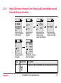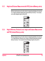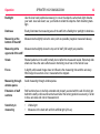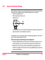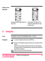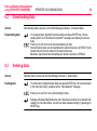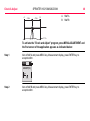
1
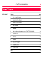
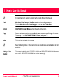
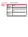
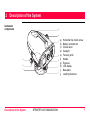
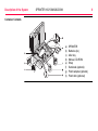
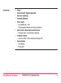
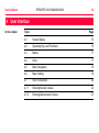
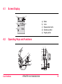
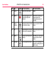
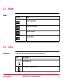
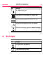
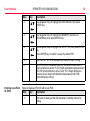
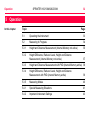
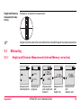
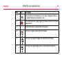
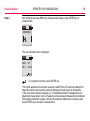
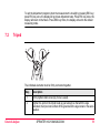
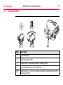
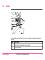
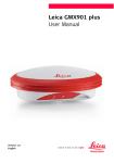
LEICA SPRINTER User Manual Version 1.2 English SPRINTER 100/100M/200/200M 2 Introduction Purchase Congratulations on the purchase of a new Leica Geosystems Digital Level. Product SPRINTER 100/100M/200/200M is the new high quality electronic digital level produced by Leica Geosystems. It is designed to make levelling easier and quicker in any construction site. It employs techniques that electronically read the special bar-coded staff and the gathered data is displayed on the screen almost instantly. Its innovative technology makes the daily surveying jobs easier. This manual contains important safety directions as well as instructions for setting up the product and operating it. Refer to "11 Safety Directions" for further information. Read carefully through the User Manual before you switch on the product. Product identification The model and the serial number of your product are indicated on the type plate. Enter the model and serial number in your manual and always refer to this information when you need to contact your agency or Leica Geosystems authorized service workshop. Type: _______________ Serial No.: _______________ Software-Version: _______________ Symbols The symbols used in this manual have the following meanings: Type Description Warning Caution Indicates an imminently hazardous situation which, if not avoided, will result in death or serious injury. Danger ) Trademarks Indicates a potentially hazardous situation or an unintended use which, if not avoided, could result in death or serious injury. Indicates a potentially hazardous situation or an unintended use which, if not avoided, may result in minor or moderate injury and/or appreciable material, financial and environmental damage. Important paragraphs which must be adhered to in practice as they enable the product to be used in a technically correct and efficient manner. All trademarks are the property of their respective owners. SPRINTER 100/100M/200/200M 3 SPRINTER 100/100M/200/200M 4 Table of Contents In this manual Chapter 1 How to Use this Manual Page 5 2 Description of the System 7 3 Measurement Preparation 10 4 User Interface 14 5 Operation 32 6 Data and Memory Management (only SPRINTER 100M/200M) 44 7 Check & Adjust 47 8 Messages 54 9 Settings 59 10 Care and Transport 61 11 Safety Directions 63 12 Technical Data 75 Index 80 1 How to Use this Manual ) It is recommended to set-up the product while reading through this manual. Path Main Menu: Data Manager\ View Data stands for this working sequence: From the Main Menu select Data Manager…. and then select View Data. Screen CONFIGURE General Menu describes the name of the screen. Page Screens can have more than one page. Units page describes a specific page of a screen. For example: ’...in CONFIGURE Units & Formats, Units page...’. Index The index is at the back of the manual. ) Keys, fields and options on the screens which are considered as self-explanatory are not explained. Validity of this manual This manual is valid for both SPRINTER 100/200 and SPRINTER 100M/200M. Sections only valid for SPRINTER 100M/200M are marked accordingly. How to Use this Manual SPRINTER 100/100M/200/200M 5 How to Use this Manual Available documentation SPRINTER 100/100M/200/200M 6 Name of documentation Description SPRINTER 100/100M/200/200M User Manual All instructions required in order to operate the instrument at its basic level are contained in this User Manual. Provides an overview of the system together with technical data and safety directions. SPRINTER 100/100M/200/200M Quick-guide 2 pages of short description on operating the instrument. 2 Description of the System Instrument components d e f g a h b i c j Sprinter_01 Description of the System SPRINTER 100/100M/200/200M a) b) c) d) e) f) g) h) i) j) Horizontal fine motion screw Battery compartment Circular level Gunsight Focusing knob Handle Eyepiece LCD display Base plate Levelling footscrew 7 Description of the System SPRINTER 100/100M/200/200M 8 Container Contents a) b) c) d) e) f) g) h) SPRINTER Batteries (4x) Allen key Manual, CD-ROM Strap Sunshade (optional) Plumb adapter (optional) Plumb bob (optional) Accessories • • • • • • • • Tripod Aluminum Staff (Region dependant) Rain cover (Optional) Sunshade (Optional) Power supply • 4 AA alkaline dry - cells • 4 Rechargeable batteries and charger (Optional) Data Transfer / Recording to external device • Computer cable - serial interface (Optional) Computer software • Leica Geo Office Tools for data downloading to PC Documentation • User Manual • Quick-guide Description of the System SPRINTER 100/100M/200/200M 9 SPRINTER 100/100M/200/200M Measurement Preparation 3 Measurement Preparation In this chapter 3.1 10 Topic Page 3.1 Battery 10 3.2 Set-up instrument 11 Battery Change battery stepby-step a a Sprinter_02 Sprinter_03 Step Description 1. Simultaneously depress the locking clips (a) on the battery cover and remove it. 2. Insert the 4 AA dry cells the right way round according to the positive and negative signs as indicated on the cover. Always replace with a complete battery set! • Do not use old and new batteries together. • Do not use batteries from different manufacturers or batteries of different types. • For type of battery, refer to Technical Data. ) ) 3. 3.2 Levelling Place the compartment back and push until a click is heard. Set-up instrument Step Description 1. Set up the tripod. Extend the legs to a suitable length and ensure that the tripod head is approximately level. Tread the tripod shoes firmly into the ground to ensure stability. 2. Mount the instrument on the tripod by screwing the tripod screw onto the base of the instrument. Measurement Preparation SPRINTER 100/100M/200/200M 11 Measurement Preparation Step 3. SPRINTER 100/100M/200/200M 12 Description Use the three levelling foot screws to center the circular bubble in order to level the instrument. Turn the telescope of the instrument perpendicular to foot screws A and B. Turn foot screws A and B simultaneously in opposite direction until the bubble is in the center of the imaginary "T". Finally turn the foot screw C until the bubble is shifted to the center of the circular vial. B A C Eyepiece Adjustment Sprinter_05 Step 4. Description Point the telescope to a uniform light surface such as a wall or a piece of paper. Turn the eyepiece until the cross hairs are sharp or distinct. Target Image Focusing Step 5. Description Use the gunsight to aim the objective lens at the staff. Turn the horizontal fine motion screw until the staff is nearly centered in the field of view and then turn the focusing knob to focus on the staff. Looking through the telescope, shift your eyes slightly up and down and if the staff and the reticle does not show any deviation or displacement against one another, then the instrument is ready for usage. Otherwise, both steps 3 and 4 should be repeated. Use only SPRINTER staff produced by Leica Geosystems ) Power ON ESC Sprinter_07 ) The instrument is ready to measure. Measurement Preparation SPRINTER 100/100M/200/200M 13 SPRINTER 100/100M/200/200M User Interface 4 14 User Interface In this chapter Topic Page 4.1 Screen Display 15 4.2 Operating Keys and Functions 15 4.3 Modes 17 4.4 Icons 17 4.5 Menu Navigation 18 4.6 Menu Setting 19 4.7 Set of Characters 22 4.7.1 Entering Numeric Values 22 4.7.2 Entering Alphanumeric Values 27 4.1 Screen Display a b MEAS e d 4.2 : 1.235m : 5.68m a) b) c) d) e) c Mode Icons Measurement units Distance symbol Height symbol Operating Keys and Functions f c ESC b a Sprinter_08 User Interface Sprinter_09 SPRINTER 100/100M/200/200M d e 15 SPRINTER 100/100M/200/200M User Interface Pos. Key Symbol 1st level functions 16 2nd level functions a) On/Off Power On or Off switch NONE b) MEAS Measuring trigger key for measuring height and distance 2nd function (Continuous measurement) with prolonged key press of 2 seconds c) Height / Distance Alternating between Height and Distance display Cursor up (when in Menu mode) d) dH Height Difference measure- Cursor down (when in Menu ment and RL computation mode) e) MENU Activation and Selection of settings ENTER key for confirmation purpose (when in Menu mode) f) Backlight LCD backlight illumination ESC key for termination of program or setting (when in Menu mode) 4.3 Modes Modes Symbol MEAS MENU ADJ TRK 4.4 Mode Measurement Mode MENU selection Mode Adjustment Mode Tracking Mode Icons Description Icons show the current status information of the instrument. Icon Description LCD backlight on Staff upright measuring mode User Interface SPRINTER 100/100M/200/200M 17 SPRINTER 100/100M/200/200M User Interface Icon Description Inverted Staff measuring mode Different levels of LCD contrast display (10% change per step) Battery icon at various capacities (0%, 25%, 50%, 75%, 100%) External power utilized (applicable to SPRINTER 100M/200M) Data stored to internal memory (applicable to SPRINTER 100M/200M) 4.5 Menu Navigation Icon Description To access the MENU, press MENU key. Press to scroll the cursor up or down. 18 Icon Description Press to select highlighted MENU item and submenu is displayed. Press to select highlighted submenu item, a "Setting…" message prompted; and display return to last measurement application. To exit from submenu, press key once will go to menu; press key again and display will return to last measuring application. Example 4.6 Selecting BEEP to ON: MENU MENU MENU 1. Input PtID 2. Input RL 3. Data Manager 4. Recording 5. Adjustment 6. Inverse Staff 7. Contrast 8. Units 9. Auto Off 10. Rounding 11. Beep 12. Baudrate MENU BEEP On Off Menu Setting No. 1. User Interface Sub Menus Input PtID Selections Descriptions To input user point ID (Applicable to SPRINTER 100M/200M) SPRINTER 100/100M/200/200M 19 SPRINTER 100/100M/200/200M User Interface No. Sub Menus Selections Descriptions 2. Input Reduced Level (RL) Input for Benchmark value / Reference Reduced Level 3. Data Manager View, Delete, Download Viewing of individual recorded data / deleting of specific measured target data Deleting of all measuring data Transferring of data via PC software (applicable to SPRINTER 100M/200M) 4. Recording Memory, OFF, External Data can be recorded in the internal memory of the instrument or externally to the external device such as data collectors.(applicable to SPRINTER 100M/200M). If the recording is set OFF, then the captured data will not be stored. 5. Adjustment None Adjustment program 6. Inverse Staff ON = Inverted mode OFF = Upright mode Setting of measurement to Inverted Staff. By default or on power on, the mode is always set to OFF. 7. Contrast 10 levels of Optimum contrast setting for LCD display. selections Contrast is set to 50% ex factory. 8. Unit M, INT ft, US ft, Ft in 1/8in Display Unit setting in meters, international feet, US feet, and ft in 1/8in 20 No. User Interface Sub Menus Selections Descriptions 9. AutoOFF ON 15 min / Power saving function. If set to ON 15 min, the OFF instrument will switch off about 15 minutes after the last key press. In the case of OFF, the instrument will be permanently switched on 10. Rounding Precise/ Standard Setting of minimum display reading: In metric: Standard = 0.001m for height and 0.01m for distance. Precise = 0.0001 m for height and 0.001m for distance In Ft: Standard (Int. and US ft) = 0.01 ft and distance = 0.1 ft Precise = 0.001 ft for height and 0.01 ft for distance. In Ft in 1/8 inch: Precise & Standard = ft-inch-1/8 inch for height and distance 11. Beep ON/OFF Acoustic signal trigger key ON or OFF 12. RS232 (applicable to SPRINTER 100M/200M) Baudrate 1200, 2400, 4800, 9600, 19200, 38400 Parity None, Odd, Even Stop Bit 1, 2 Data Bit 7, 8 SPRINTER 100/100M/200/200M 21 SPRINTER 100/100M/200/200M User Interface 4.7 22 Set of Characters Reduced level (RL) Reduced level (RL) numeric input consists of 0 ~ 9, space, decimal, Ft in 1/8 inch separator, the "+" and "-" signs. Point ID (PtID) Point ID (PtID) alphanumeric input consists of a ~ z, 0 ~ 9 and space. 4.7.1 Description Entering Numeric Values Numeric fields can only contain numeric values, positive / negative signs, Ft in 1/8 inch separator and decimal points. Numeric fields are e.g.: reference level. Initializing the numeric REFERENCE reduced level (RL) input: MENU MENU MENU 1. Input PtID 2. Input RL 3. Data Manager 4. Recording Enter Ref. RL (m) Enter Ref. RL (m) RL: RL: 100.038 Step 1. Key Description Press Menu key to start menu for selection. RL : 100.038m Meas. Reference To change RL goto menu Step Entering a new Reduced Level (RL) value User Interface Key Description 2. Use navigation keys to highlight the INPUT RL, then press ENTER key. 3. Input field for Reference reduced level is displayed and ready for input / editing. 4. Press ENTER key to confirm / accept the REFERENCE Reduced level. 5. Reduced level function is initialized and measurement is taken according to section "5.3.2 Height Difference, Reduced Level, Height and Distance Measurement (internal Memory not active)". Replace displayed value with a new value: Step Key Description 1. The cursor is always at the first character in standby manner for editing. 2. Use scrolling keys to highlight the desired character in the entry field. 3. Acknowledge the character entry by pressing the ENTER key. 4. The next entry field (to the right) is highlighted for further editing. 5. Repeat step 2 and 3 until a complete value has been entered. SPRINTER 100/100M/200/200M 23 SPRINTER 100/100M/200/200M User Interface Step Edit displayed value Key 24 Description 6. To accept the new value, simply press the ENTER key with "space" character in the entry field at the end of the value string. 7. A "Change RL. Are You Sure?" message is prompted, press ENTER key to confirm change. 8. Press key to restore old value. Edit a few digits of displayed value: Step Key Description 1. The cursor is always at the first character in standby manner for editing, showing the last entered reduced level. 2. If there is no change for any particular character in the existing entry field, press ENTER key to accept the old entry. 3. Highlight the desired character to be changed in entry field with the scrolling keys. 4. Acknowledge the character entry by pressing the ENTER key. 5. The next entry field (to the right) is highlighted for further editing. 6. Repeat step 2 to 4 until a complete value has been entered. Step To discard entry and invalid data entry Key Description 7. To accept the new value, simply press the ENTER key with "space" character in the entry field at the end of the value string. 8. A "Change RL. Are You Sure?" message is prompted, press ENTER key to confirm change. 9. Press key to restore old value. Step Key/Screen Description 1. Press key to discard entry and restore old value. 2. When an "INVALID" data is being input, an "Invalid Entry" message is prompted. E105 Invalid Entry ! 3. Accepting character in the existing value User Interface Press key to continue. If there is no change for any particular character in the existing entry field, press ENTER key to accept the old entry. SPRINTER 100/100M/200/200M 25 SPRINTER 100/100M/200/200M User Interface Clearing all the existing entry field 26 Highlighting the first entry field with "SPACE" and press ENTER key to clear the entire last reduced level input value. Default Reference Reduced Level • • If no Reference reduced level is input; the default value equals to zero, i.e. 0.000. The display value is to 4 and 3 decimals in meter and feet (Int and US ft) respectively for Precise setting; 3 and 2 decimals in meter and feet (Int and US ft) respectively for Standard setting. For ft in 1/8 inch, the display value will be shown in Precise setting. Change reduced level value • Once Reference staff measurement is measured as in section "5.3.2 Height Difference, Reduced Level, Height and Distance Measurement (internal Memory not active)", then the last input REFERENCE reduced level cannot be changed. At this stage, if any attempt to change the last input REFERENCE reduced level in menu INPUT RL, a "RL Change Not Allowed!" message will be prompted. To change the input REFERENCE reduced level, follow these steps: • Discontinue the present reduced level measurement by pressing HEIGHT/DISTANCE key to exit to default measurement. • Go to menu select INPUT RL and carry on with the steps in section 4.7.1 to edit a new REFERENCE reduced level value. • Start reduced level measurement with NEW REFERENCE reduced level as in section "5.3.2 Height Difference, Reduced Level, Height and Distance Measurement (internal Memory not active)". • 4.7.2 Entering Alphanumeric Values Description Alphanumeric fields can contain numeric as well as alphanumeric values e.g.: PtID. Initializing the alphanumeric Point ID (PtID) input with following steps: MENU MENU 1. Input PtID 2. Input RL 3. Data Manager 4. Recording RECORDING Memory Off Ext. MENU 1. Input PtID 2. Input RL 3. Data Manager 4. Recording MENU Enter Point No. PtlD: MENU Enter Point No. PtlD: BM1 Step 1. User Interface PtlD : BM1 RL: 0.000 Meas. Reference To change RL & ID goto menu Key Description Press Menu key to start menu for selection. SPRINTER 100/100M/200/200M 27 SPRINTER 100/100M/200/200M User Interface Step Entering a new Point ID (PtID) Key 28 Description 2. Use navigation keys to highlight the RECORDING, then press ENTER key. 3. Use navigation keys to highlight the MEMORY (submenu of RECORDING), then press ENTER key. 4. Use navigation keys to highlight the INPUT PtID, then press ENTER key. Press ENTER key to confirm / accept the edited PtID. 5. Input field for Point ID is displayed and ready for input / editing. 6. Point ID function is initialized (Memory ON) and measurement is taken according to section "5.3.3 Height and Distance Measurement with PtID (internal Memory active)" and "5.3.4 Height Difference, Reduced Level, Height and Distance Measurement with PtID (internal Memory active)". Replace displayed Point ID with a new PtID: Step 1. Key Description The cursor is always at the first character in standby manner for editing. Step Edit displayed Point ID (PtID) User Interface Key Description 2. Use scrolling keys to highlight the desired character in the entry field. 3. Acknowledge the character entry by pressing the ENTER key. 4. The next entry field (to the right) is highlighted for further editing. 5. Repeat step 2 and 3 until a complete value has been entered. 6. To accept the new Point ID, simply press the ENTER key with "SPACE" character in the entry field at the end of the Point ID string. 7. Press key to restore old value. Edit a few characters of displayed (old) Point ID: Step Key Description 1. The cursor is always at the first character in standby manner for editing. 2. If there is no change for any particular character in the existing entry field, press ENTER key to accept the old entry. 3. Highlight the desired character to be change in entry field with the scrolling keys. SPRINTER 100/100M/200/200M 29 SPRINTER 100/100M/200/200M User Interface Step Key 30 Description 4. Acknowledge the character entry by pressing the ENTER key. 5. The next entry field (to the right) is highlighted for further editing. 6. Repeat step 2 to 4 until a complete revised Point ID has been entered. 7. To accept the new Point ID, simply press the ENTER key with "SPACE" character in the entry field at the end of the Point ID string. 8. Press key to restore old value. To discard entry Press key to discard entry and restore old value. Accepting character in the existing PtID If there is no change for any particular character in the existing entry field, press ENTER key to accept the old entry. Point ID increment Point ID will be automatically incremented by 1 from the last Point ID if POINT ID input field is not updated manually. Point ID not incremented When Point ID is not able to be incremented, a "Point No. Not Incremented!" message will be prompted; e.g. 8 alpha characters input. Clearing all the existing entry field User Interface Highlighting the first entry field with "SPACE" and press ENTER key to clear the entire last Point ID input value. SPRINTER 100/100M/200/200M 31 SPRINTER 100/100M/200/200M Operation 5 32 Operation In this chapter Topic Page 5.1 Operating the Instrument 33 5.2 Measuring in Progress 34 5.3.1 Height and Distance Measurement (internal Memory not active) 35 5.3.2 Height Difference, Reduced Level, Height and Distance Measurement (internal Memory not active) 37 5.3.3 Height and Distance Measurement with PtID (internal Memory active) 39 5.3.4 Height Difference, Reduced Level, Height and Distance Measurement with PtID (internal Memory active) 39 5.3.5 Measuring Modes 40 5.4.1 Special Measuring Situations 41 5.4.2 Important Instrument Settings 43 5.1 Operating the Instrument Switching ON/OFF b a a) b) Sprinter_24 • ON/OFF switch Measure button Switching ON: Press briefly. Version # : Serial # : SPRINTER 100M Logo displayed upon switching on Operation Press any key to view and release version display SPRINTER 100/100M/200/200M 33 SPRINTER 100/100M/200/200M Operation 5.2 34 Measuring in Progress Measurement Height and distance measurement. MEAS : >>>> : >>>> MEAS PtlD : 3 : >>>> : >>>> MEAS PtlD : 3 RL: dH: : >>>> >>>> : >>>> General Notices • • • Height and distance measurement with PtID. Memory should be ON to starts PtID display ) Height, distance, reduced level and height difference measurement with PtID. Memory should be ON to starts PtID display ) First check and adjust the line-of-sight errors, then the circular level on the instrument and then the staff. • Before starting work in the field • After long storage periods • After long transportation Keep the optics clean. Dirt or condensation on the optics can limit measurements. Before starting work, let the instrument adjust to the ambient temperature (approx. 2 minutes per °C of temperature difference). Height and Distance measurement (electronic) ) 5.3 Example of an electronic measurement: Always aim at the center of bar code staff and focus the staff image for accurate measurement. Measuring 5.3.1 Height and Distance Measurement (internal Memory not active) MEAS : _____ : >>>> : 1.235m : _____ : >>>> : 5.68m Measurement Standby Mode Operation Measuring in progress Measurement with height and distance SPRINTER 100/100M/200/200M : 1.235m Measurement with height only : 5.68m Measurement with distance only 35 SPRINTER 100/100M/200/200M Operation Step Key 36 Description 1. Press to switch on the instrument, Leica logo is displayed follow by the default measurement standby mode. 2. Aim at staff and focus. Lightly trigger the measurement key to activate measurement. 3. Height and distance measurement is displayed. 4. Press key to toggle to the height only display. 5. Press key once again to toggle to the distance only display. 6. Press key once again display return to the height and distance. 5.3.2 Height Difference, Reduced Level, Height and Distance Measurement (internal Memory not active) MEAS RL : 100.038m Meas. Reference : >>>> : 1.235m To change RL goto menu : >>>> : 5.68m Prompt message with input RL Measuring in progress Measurement to reference with height and distance Meas. Target ! Prompt message measure to target MEAS RL: dH: : >>>> : >>>> RL: dH: : : Measurement in progress Completion of measurement to target Step 1. Operation Key/Screen 99.138m - 0.900 m 2.135 m 31.11 m Description Press key to start height difference and reduced level function. SPRINTER 100/100M/200/200M 37 SPRINTER 100/100M/200/200M Operation Step Key/Screen 38 Description 2. A message "Meas. Reference" with input reduced level is displayed. 3. Press measuring key to initiate measurement with respect to the Reference staff / Benchmark. 4. Reference height and distance measurement is displayed; follow by a message "Meas. Target!" prompted. 5. Again, press measure key to start measurement with reference to target point. 6. The following results are displayed accordingly;- target reduced level (RL), target height difference (dH) with respect to the reference staff, height and distance of target point. 7. If no measurement is made to the Reference staff, a message "No Reference Point!" is prompted. No Reference Point ! 8. Measurement to the Reference staff / Benchmark is required before the measurements to targets is allowed by the system. 5.3.3 Height and Distance Measurement with PtID (internal Memory active) With the internal memory set to active mode; the measuring procedures is the same as "5.3.1 Height and Distance Measurement (internal Memory not active)". The measurement results displayed together with point ID. PtlD : : : 5.3.4 1 1.235 m 5.68 m Height Difference, Reduced Level, Height and Distance Measurement with PtID (internal Memory active) With the internal memory set to active mode; the measuring procedures is the same as "5.3.2 Height Difference, Reduced Level, Height and Distance Measurement (internal Memory not active)". The measurement results displayed together with point ID. PtlD : RL: dH: : : Operation 2 99.138m - 0.900m 2.135m 31.11 m SPRINTER 100/100M/200/200M 39 SPRINTER 100/100M/200/200M Operation ) 5.3.5 40 With the Recording Ext set to active mode; the measuring procedure is the same as 5.3.3 and 5.3.4 without displaying the diskette icon. Measuring Modes Description Single measurement mode Tracking measurement mode There are 2 different measuring modes to select: Single measurement and Tracking measurement.To Abort the measurement during single measuring mode by triggering the measuring key. Step Key/Screen Description 1. To activate Single measurement, aim and focus at the bar code staff. 2. Then lightly trigger the measuring key once to start the single measurement. 3. An icon is displayed at the top left of the screen, to indicate the present measuring mode. Step Key/Screen Description 1. To start Tracking measurement, aim and focus at the bar code staff. 2. Then press and hold the measuring key for 1-2 seconds to start the tracking measuring mode, a "Start Tracking!" message is displayed and measurement starts. Step Key/Screen Description 3. An icon is displayed at the top left of the screen to indicate the present measuring mode. 4. Measurement after measurement is measured and displayed but not recorded Recording is inactivated in tracking measuring mode. ) 5.4 5. To stop the tracking measuring mode, simply press the measuring key or dH or MENU key. A "Stop Tracking!" message is displayed and measurement stops. 6. Results of last measurement will be displayed. Technical Hints for Measurements 5.4.1 Vibrations Operation Special Measuring Situations Vibrations at the instrument, e.g. due to wind can be damped by touching the upper third of the tripod steadying the tripod. SPRINTER 100/100M/200/200M 41 SPRINTER 100/100M/200/200M Operation 42 Backlight Use the lens hood (optional accessory) to cover the objective when back light disturbs your work. As a last resort, use your hands to shield the objective from disturbing backlight. Darkness Evenly illuminate the measuring area of the staff with a flashlight or spotlight in darkness. Measuring at the bottom of the staff Measurements slightly below the zero point are possible (negative measured values). Measuring at the upper end of the staff Measurements slightly above the top end of staff (full length) are possible. Shade Shaded patterns on the staff normally do not affect the measured results. Extremely dark shade can have the same effects as an interfering cover has on the field-of-view. Focus A slightly unfocussed image does not influence the measuring time and the accuracy. When large focus errors occur, measurement is stopped. Measuring through window panes Avoid measuring through window panes. Extension of staff sections Staff sections have to be fully extended and properly secured with the aid of locking pin behind the staff (a click sound can be heard when the locking position is secured), in order to have accurate and correct measurement. Sensitivity in measuring • • Visible light Measures in the dark with uniform artificial light (20 Lux) 5.4.2 Important Instrument Settings Before starting any measurement, use the following list to check how the measurement is to proceed. Set or change the relevant instrument parameters when required • Current line-of-sight error ok? • Which measurement mode to use? Collimation error α Sprinter_22 The Collimation error (α) is the vertical angle between the actual line-of-sight and the ideal horizontal line. It is determined by a level test. The collimation error in the instrument system is automatically applied as a correction to every electronic height reading of the staff. There are two ways of determining the line-of-sight error: 1. Using the integrated field level test procedure or the laboratory test before the collimator test (Sprinter only). See 2-peg level test (respective with collimator test). 2. Determine the values through your own measurements with procedures recommended in this booklet and enter them into the system ([MENU]/ Adjust / System by pressing the ENTER key). Operation SPRINTER 100/100M/200/200M 43 Data and Memory Management (only SPRINTER 100M/200M) 6 SPRINTER 100/100M/200/200M 44 Data and Memory Management (only SPRINTER 100M/200M) In this chapter Description Topic Page 6.1 Viewing Data 45 6.2 Downloading Data 46 6.3 Deleting Data 46 • • • • • • • The data is stored in internal memory or to an external device such as PDA, Data Collector or PC through the RS232 interface. Data is stored in two memory types: 1. Measurement memory: Measurements to various target points. 2. Measured fixed point memory: Measurements to the Reference points. Starting a job, all the available internal memory is reserved for measurements and measured fixed points. When the internal memory is low, a "Low Memory!" message is flashed at every 5 measurements. Until the internal memory is full, a "Memory Full!" message is displayed. An internal memory can store a maximum of 500 measurements data. If a measurement is not successful, e.g. invalid measurement, staff too far, etc, no measurement data is recorded. In menu Data Manager; Viewing Data, Downloading Data and Deleting Data routine can be performed. Example of saved Data formats MENU MENU 34/38 33/38 PtlD : : : A1 RfID : RL: dH: 1.249m 2.02m Saved data with PtID, height, distance and data counter. 6.1 PtlD : : A2 A1 100.330m 0.000m 1.249m Saved data with PtID, reference PtID, reduced level, height difference, height and data counter. Viewing Data Access Viewing data Viewing data is accessed via the Data Manager submenu - View Data. To view data, highlight View Data and press ENTER key. Each press of the navigation keys allows the viewing of one measurement data at a time. A Data Point Counter (fraction number) located at first row of stored measurement data to indicate the current data sequence (numerator) and the total number (denominator) of data stored. Press key to exit from menu after viewing of data. Data and Memory Management (only SPRINTER 100M/200M) SPRINTER 100/100M/200/200M 45 Data and Memory Management (only SPRINTER 100M/200M) 6.2 46 Downloading Data Access Downloading data is access via the Data Manager submenu - Download Data. Downloading data 6.3 SPRINTER 100/100M/200/200M To download data, highlight Download Data and press ENTER key; "Downloading Data!" and "Download Completed!" messages are displayed consecutively. Press key to exit from menu after downloading of data. Internal memory data can be downloaded to external devices via RS232. Downloaded data can then be edited in the external devices. Baudrate, stop bit and data bit settings are found in submenu of RS232. Deleting Data Access Deleting data Deleting data is access via the Data Manager submenu - Delete Data. To delete data, highlight Delete Data and press ENTER key, all the stored data in the internal memory is deleted with a "Data Deleted!" message. Press key to exit from menu after deleting of data. Deleting individual data (Reference point data does not allow to be deleted individually) in View Data mode, current view data is deleted simply by pressing the ENTER key. 7 Check & Adjust In this chapter Description 7.1 Topic Page 7.1 Procedures 47 7.2 Tripod 51 7.3 Circular Level 52 7.4 Reticle 53 Both optical and electronic collimation error can occur in the SPRINTER 100/100M/200/200M. Electronic staff readings are automatically corrected with the collimation error stored in the SPRINTER 100/100M/200/200M while the optical collimation errors need to be eliminated by adjusting the reticle. The instrument offers A x Bx field procedure for the electronic measurements (A and B are the staffs positions and x is the instrument position). Procedures Set up the SPRINTER 100/100M/200/200M in the center of the two staffs A and B. The distance between the two staffs is approximately 30m. Check & Adjust SPRINTER 100/100M/200/200M 47 SPRINTER 100/100M/200/200M Check & Adjust A ~15m ~15m B 48 A B Staff A Staff B To activate the "Check and Adjust" program, press MENU-ADJUSTMENT and the first screen of the application appears as indicated below: Step 1 Aim at Staff A and press MEAS key. Measurement display, press ENTER key to accept/confirm. MENU ADJ ADJUST (1/4) MEAS Step 2 Aim at Staff B and press MEAS key. Measurement display, press ENTER key to accept/confirm. MENU ADJ ADJUST (2/4) MEAS Now shift the SPRINTER towards staff A and set it up at about 3 m to staff A. A Step 3 ~3m ~27m B Aim at Staff B and press MEAS key. Measurement display, press ENTER key to accept/confirm. MENU ADJ ADJUST (3/4) MEAS Check & Adjust SPRINTER 100/100M/200/200M 49 SPRINTER 100/100M/200/200M Check & Adjust Step 4 50 Aim at Staff A and press MEAS key. Measurement display, press ENTER key to accept/confirm. MENU ADJ ADJUST (4/4) MEAS The new collimation error is displayed. MENU ADJ Error = 5.0” dH: = 0.7 mm Accept To accept the correction, press ENTER key. If the reticle adjustment is required, reverse the staff B for the E scale bar reading then adjust the reticle using the tool provided by following through the given instructions. In the event where warning message e.g. "Invalid Measurement" is displayed for any adjustment measurement, carry on measuring until a successful measurement is obtained (Presumably instrument is setup correctly and external conditions are conducive) and press ENTER key to accept the measurement. To quit the Adjustment program (when the measurement is invalid) by pressing ESC key; press ESC key once, the display will go to last Adjustment step. Press ESC key twice, the display will return to the Menu. Press ESC key thrice, the display will exit to the default measuring mode. 7.2 Tripod a S i t b 17 The individual elements must be firmly connected together. Step Check & Adjust Description 1. Firmly tighten Allen screw (b) (if one is used). 2. Tighten the joint on the tripod head (a) just enough so that with the legs extended, the tripod can be lifted off the ground and the legs remain in the same position. SPRINTER 100/100M/200/200M 51 SPRINTER 100/100M/200/200M Check & Adjust 7.3 52 Circular Level c a b Sprinter_18 Step Sprinter_19 Description 1. Level instrument. 2. Turn instrument by 180°. 3. Center bubble if it extends beyond the centering circle. 4. Correct half of the error with the Allen key. ) Repeat steps 1 to 4 until the circular level bubble is centered at any random telescope pointing. 7.4 Reticle Sprinter_20 If the collimation error exceeds 3 mm over 60 m distance, the collimation needs to be adjusted. Step Check & Adjust Description 1. Turn Allen key until design value is reached. 2. Check collimation. SPRINTER 100/100M/200/200M 53 SPRINTER 100/100M/200/200M Messages 8 Messages In this chapter 8.1 54 Topic Page 8.1 List of the "Error" Messages 54 8.2 List of the "Operation" Messages 57 List of the "Error" Messages No. Error message Counter measure / causes E99 System Error, Contact Services ! Hardware faults or file errors or adjustment errors or setting errors rendering instrument not working properly. E100 Low Battery ! Change to new or freshly charged batteries. E101 Point No. Not Incremented ! Change the PtID. Max. PtID is 99999999 and do not end any 8 characters string with an alphabet character. E102 Too Bright ! Darken staff or reduce lighting on staff or shade the objective telescope. Messages No. Error message Counter measure / causes E103 Too Dark ! Light up staff uniformly. E104 No Staff ! Check targeting. E105 Invalid Entry ! Check the entry / input. E106 Out Of Level ! Level the instrument. E107 Memory Full ! Set internal memory to OFF and continue measurement without recording OR download stored data to an external device and continue measurement with internal memory ON after deleting all the internal memorized data. E108 Data File Error ! Data file error. E109 Low Memory ! Prepare to download data to external device, in order to continue further measurement with recording after deleting all the internal memorized data. E110 Target Too Close ! Move staff or instrument further apart. E111 Target Too far ! Move staff or instrument closer together. E112 Too Cold ! Stop working, external temperature is outside the instrument operating temperature. E113 Too Hot ! Stop working, external temperature is outside the instrument operating temperature. SPRINTER 100/100M/200/200M 55 SPRINTER 100/100M/200/200M Messages 56 No. Error message Counter measure / causes E114 Invalid Measurement ! Make another measurement. If further measurement proved to be futile, check staff position and Inverse Staff setting, check the lighting condition at the staff and stray light, check focusing and targeting, check if sufficient length of barcode in the field of view. E115 Temperature Sensor Error ! Cover the objective telescope with a hand and switch ON the instrument. Hardware communication failed. E116 Adjustment Error ! Carry out the adjustment with guided steps, make sure instrument is level and staff is truly vertical in normal position. Collimation is out of correction range. E117 RL Change Not Allowed ! Exit to default measurement mode by pressing HEIGHT/DISTANCE key, and change the Reference reduced level in the INPUT RL menu mode. E119 Staff Blocked Not enough barcode length for measurement. E120 Image sensor Error! Contact services. E121 Adjustment Inverse Staff Not Allowed! Check the staff orientation. 8.2 List of the "Operation" Messages Messages Message Counter measure / remark Start Tracking ! Tracking mode starts. Stop Tracking ! Tracking mode stops. Tracking Hold ! Press measuring key for 1-2 seconds to restart tracking mode. Tracking will hold after 10 unsuccessful measurements. Downloading Data ! Downloading of data from the internal memory to an external device is in progress. Download Completed ! System is successfully downloaded the internal memory data to an external device. No Data In Memory ! No data is stored in the internal memory. Delete. Are You Sure? Questionnaire to prompt user to confirm the deletion of a data (in View Data mode) or all the data (in Delete Data mode) in the internal memory. Data Deleted ! System confirmation that a data or all the data in the internal memory is deleted. SPRINTER 100/100M/200/200M 57 SPRINTER 100/100M/200/200M Messages 58 Message Counter measure / remark Can't Delete ! Reference reduced level measurement is not allowed to be deleted by single data deletion method. No Reference Point ! Aim, focus and measure to a Reference point. In Height Difference and Reduced Level measurement, a Reference point measurement is required. Change RL. Are You Sure? Question to prompt user if changing of Reference reduced level to confirm. Wait ! File System Clean Up ! Cleaning up of temporary files/system files. Shut Down ! System is switching OFF. Sand Clock Icon Please wait! System task in progress. Meas Target Aim to target staff and press measuring button. Setting… System parameter setting in progress. 9 Settings In this chapter 9.1 Topic Page 9.1 System 59 9.2 Data Output 60 9.3 Communication 60 System ) Contains the system settings. PtID & Increment Enter PtID • manually or • automatic PtID increment if PtID is not updated manually. Collimation error Displays the new collimation error immediately after the field adjustment. Upon accepting this new collimation error, the system will correct the electronic height measurement with this collimation error magnitude. Settings SPRINTER 100/100M/200/200M 59 SPRINTER 100/100M/200/200M Settings 9.2 Data Output ) Important settings for measuring and display. GSI-format 9.3 60 Data via interface and data export in GSI-format. • GSI-8 8-data characters output format (83..00+12345678). These data words can hold alpha as well as numeric data. • GSI-16 16-data characters output format (83..00+1234567890123456 ). These data words can hold alpha as well as numeric data. Communication Communications parameters of the RS232 interface for data transfer from instrument to computer / external device. Leica standard settings • • • • • 19200 baud, 8 data bits (8 data bits are automatically set when for parity "None" is set.) No parity (No parity [when data bits = 8]) CR/LF (New line and line feed) 1 stop bit 10 Care and Transport In this chapter 10.1 Topic Page 10.1 Transport 61 10.2 Storage 62 10.3 Cleaning and Drying 62 Transport Transport in the field When transporting the equipment in the field, always make sure that you • either carry the product in its original transport container, • or carry the tripod with its legs splayed across your shoulder, keeping the attached product upright. Transport in a road vehicle Never carry the product loose in a road vehicle, as it can be affected by shock and vibration. Always carry the product in its transport container and secure it. Shipping When transporting the product by rail, air or sea, always use the complete original Leica Geosystems packaging, transport container and cardboard box, or its equivalent, to protect against shock and vibration. Care and Transport SPRINTER 100/100M/200/200M 61 SPRINTER 100/100M/200/200M Care and Transport Shipping, transport of batteries 10.2 62 When transporting or shipping batteries, the person in charge of the product must ensure that the applicable national and international rules and regulations are observed. Before transportation or shipping, contact your local passenger or freight transport company. Storage Product Respect the temperature limits when storing the equipment, particularly in summer if the equipment is inside a vehicle. Refer to "12 Technical Data" for information about temperature limits. Field adjustment After long periods of storage inspect the field adjustment parameters given in this user manual before using the product. 10.3 Cleaning and Drying Objectives and eyepiece • • • Blow dust off lenses. Never touch the glass with your fingers. Use only a clean, soft, lint-free cloth for cleaning. If necessary, moisten the cloth with water or pure alcohol. Do not use other liquids; these may attack the polymer components. Damp products Dry the product, the transport container, the foam inserts and the accessories at a temperature not greater than 40°C/108°F and clean them. Do not repack until everything is completely dry. Cables and plugs Keep plugs clean and dry. Blow away any dirt lodged in the plugs of the connecting cables. 11 Safety Directions In this chapter 11.1 Topic Page 11.1 General 63 11.2 Intended Use 64 11.3 Limits of Use 65 11.4 Responsibilities 65 11.5 International Warranty, Software Licence Agreement 66 11.6 Hazards of Use 67 11.7 Electromagnetic Compatibility EMC 72 11.8 FCC Statement, Applicable in U.S. 73 General Description Safety Directions The following directions should enable the person responsible for the product, and the person who actually uses the equipment, to anticipate and avoid operational hazards. The person responsible for the product must ensure that all users understand these directions and adhere to them. SPRINTER 100/100M/200/200M 63 SPRINTER 100/100M/200/200M Safety Directions 11.2 64 Intended Use Permitted use • • Electronic and optical height and distance measurements to a staff. Recording of measurement data. Adverse use • • • • • • Use of the product without instruction. Aiming directly to the sun. Use outside of the intended limits. Disabling safety systems. Removal of hazard notices. Opening the product using tools, for example screwdriver, unless this is specifically permitted for certain functions. Modification or conversion of the product. Use after misappropriation. Use of products with obviously recognizable damages or defects. Use with accessories from other manufacturers without the prior explicit approval of Leica Geosystems. Inadequate safeguards at the surveying site, for example when measuring on roads. • • • • • Warning Adverse use can lead to injury, malfunction and damage. It is the task of the person responsible for the equipment to inform the user about hazards and how to counteract them. The product is not to be operated until the user has been instructed on how to work with it. 11.3 Limits of Use Environment Suitable for use in an atmosphere appropriate for permanent human habitation: not suitable for use in aggressive or explosive environments. Danger Local safety authorities and safety experts must be contacted before working in hazardous explosive areas, or in close proximity to electrical installations or similar situations by the person in charge of the product. 11.4 Responsibilities Manufacturer of the product Leica Geosystems AG, CH-9435 Heerbrugg, hereinafter referred to as Leica Geosystems, is responsible for supplying the product, including the user manual and original accessories, in a completely safe condition. Manufacturers of non Leica Geosystems accessories The manufacturers of non Leica Geosystems accessories for the product are responsible for developing, implementing and communicating safety concepts for their products, and are also responsible for the effectiveness of those safety concepts in combination with the Leica Geosystems product. Person in charge of the product The person in charge of the product has the following duties: • To understand the safety instructions on the product and the instructions in the user manual. • To be familiar with local regulations relating to safety and accident prevention. Safety Directions SPRINTER 100/100M/200/200M 65 SPRINTER 100/100M/200/200M Safety Directions • Warning 11.5 66 To inform Leica Geosystems immediately if the product and the application becomes unsafe. The person responsible for the product must ensure that it is used in accordance with the instructions. This person is also accountable for the training and the deployment of personnel who use the product and for the safety of the equipment in use. International Warranty, Software Licence Agreement International Warranty The International Warranty can be downloaded from the Leica Geosystems AG home page at http://www.leica-geosystems.com/internationalwarranty or received from your Leica Geosystems dealer. Software Licence Agreement This product contains software that is preinstalled on the product, or that is supplied to you on a data carrier medium, or that can be downloaded by you online pursuant to prior authorization from Leica Geosystems. Such software is protected by copyright and other laws and its use is defined and regulated by the Leica Geosystems Software Licence Agreement, which covers aspects such as, but not limited to, Scope of the Licence, Warranty, Intellectual Property Rights, Limitation of Liability, Exclusion of other Assurances, Governing Law and Place of Jurisdiction. Please make sure, that at any time you fully comply with the terms and conditions of the Leica Geosystems Software Licence Agreement. Such agreement is provided together with all products and can also be found at the Leica Geosystems AG home page at http://www.leica-geosystems.com/swlicense or your Leica Geosystems dealer. You must not install or use the software unless you have read and accepted the terms and conditions of the Leica Geosystems Software Licence Agreement. Installation or use of the software or any part thereof, is deemed to be an acceptance of all the terms and conditions of such licence agreement. If you do not agree to all or some of the terms of such licence agreement, you may not download, install or use the software and you must return the unused software together with its accompanying documentation and the purchase receipt to the dealer from whom you purchased the product within ten (10) days of purchase to obtain a full refund of the purchase price. 11.6 Hazards of Use Warning The absence of instruction, or the inadequate imparting of instruction, can lead to incorrect or adverse use, and can give rise to accidents with far-reaching human, material, financial and environmental consequences. Precautions: All users must follow the safety directions given by the manufacturer and the directions of the person responsible for the product. Caution Watch out for erroneous measurement results if the product has been dropped or has been misused, modified, stored for long periods or transported. Precautions: Periodically carry out test measurements and perform the field adjustments indicated in the user manual, particularly after the product has been subjected to abnormal use and before and after important measurements. Safety Directions SPRINTER 100/100M/200/200M 67 SPRINTER 100/100M/200/200M Safety Directions Danger 68 Because of the risk of electrocution, it is very dangerous to use poles and extensions in the vicinity of electrical installations such as power cables or electrical railways. Precautions: Keep at a safe distance from electrical installations. If it is essential to work in this environment, first contact the safety authorities responsible for the electrical installations and follow their instructions. Caution Strong magnetic fields in the immediate vicinity (e.g. transformers, melting furnaces…) may influence the compensator and lead to measuring errors. Precautions: When measuring near strong magnetic fields, check results for plausibility. Warning By surveying during a thunderstorm you are at risk from lightning. Precautions: Do not carry out field surveys during thunderstorms. Caution Be careful when pointing the product towards the sun, because the telescope functions as a magnifying glass and can injure your eyes and/or cause damage inside the product. Precautions: Do not point the product directly at the sun. Warning Inadequate securing of the surveying site can lead to dangerous situations, for example in traffic, on building sites, and at industrial installations. Precautions: Always ensure that the survey site is adequately secured. Adhere to the regulations governing safety and accident prevention and road traffic. Warning If computers intended for use indoors are used in the field there is a danger of electric shock. Precautions: Adhere to the instructions given by the computer manufacturer with regard to field use in conjunction with Leica Geosystems products. Caution If the accessories used with the product are not properly secured and the product is subjected to mechanical shock, for example blows or falling, the product may be damaged or people may sustain injury. Precautions: When setting-up the product, make sure that the accessories, for example tripod, tribrach, connecting cables, are correctly adapted, fitted, secured, and locked in position. Avoid subjecting the product to mechanical stress. Caution When using a vertical staff supported by one brace there is always the danger of falling (e.g. by wind gusts) and therefore danger of damage to equipment and danger of personal injuries. Precautions: Never leave a vertical staff supported by a brace unsupervised (person at the staff). Safety Directions SPRINTER 100/100M/200/200M 69 SPRINTER 100/100M/200/200M Safety Directions Danger 70 Using rechargeable batteries with an unsuitable charger may cause fire and explosions. Precautions: Only use rechargeable batteries and its appropriate charger recommended by Leica Geosystems. Warning Short circuited battery terminals can overheat and cause injury or fire, for example by storing or transporting in pockets if battery terminals come in contact with jewellery, keys, metallized paper of other materials. Precautions: Make sure that the battery terminals do not come into contact with metallic objects. Warning Mixed use of rechargeable batteries with dry cell batteries at the same time, or the use of different types and/or brands of batteries (both rechargeable and dry cell types) at the same time, can cause the batteries to leak, explode or begin to burn. Precautions: Do not mix rechargeable batteries together with dry cells at the same time. Use only batteries of the same type and brand at the same time. Caution During the transport, shipping or disposal of batteries it is possible for inappropriate mechanical influences to constitute a fire hazard. Precautions: Before shipping the product remove the batteries from their compartment. Before disposing the batteries, discharge the batteries by running the product until they are flat. When transporting or shipping batteries, the person in charge of the product must ensure that the applicable national and international rules and regulations are observed. Before transportation or shipping contact your local passenger or freight transport company. Caution If the product is intended not to use for a long time, and the batteries are in, their discharge could damage the equipment! Precautions: Remove batteries before putting instrument away. Warning High mechanical stress, high ambient temperatures or immersion into fluids can cause leackage, fire or explosions of the batteries. Precautions: Protect the batteries from mechanical influences and high ambient temperatures. Do not drop or immerse batteries into fluids. Warning If the product is improperly disposed of, the following can happen: • If polymer parts are burnt, poisonous gases are produced which may impair health. • If batteries are damaged or are heated strongly, they can explode and cause poisoning, burning, corrosion or environmental contamination. • By disposing of the product irresponsibly you may enable unauthorized persons to use it in contravention of the regulations, exposing themselves and third parties to the risk of severe injury and rendering the environment liable to contamination. • Improper disposal of silicone oil may cause environmental contamination. Precautions: The product must not be disposed with household waste. Dispose of the product appropriately in accordance with the national regulations in force in your country. Always prevent access to the product by unauthorized personnel. Safety Directions SPRINTER 100/100M/200/200M 71 SPRINTER 100/100M/200/200M Safety Directions 72 Product specific treatment and waste management information can be downloaded from the Leica Geosystems home page at http://www.leica-geosystems.com/treatment or received from your Leica Geosystems dealer. 11.7 Electromagnetic Compatibility EMC Description The term Electromagnetic Compatibility is taken to mean the capability of the product to function smoothly in an environment where electromagnetic radiation and electrostatic discharges are present, and without causing electromagnetic disturbances to other equipment. Warning Electromagnetic radiation can cause disturbances in other equipment. Caution There is a risk that disturbances may be caused in other equipment if the product is used in conjunction with accessories from other manufacturers, for example field computers, personal computers, two-way radios, non-standard cables or external batteries. Although the product meets the strict regulations and standards which are in force in this respect, Leica Geosystems cannot completely exclude the possibility that other equipment may be disturbed. Precautions: Use only the equipment and accessories recommended by Leica Geosystems. When combined with the product, they meet the strict requirements stipulated by the guidelines and standards. When using computers and two-way radios, pay attention to the information about electromagnetic compatibility provided by the manufacturer. Caution Disturbances caused by electromagnetic radiation can result in erroneous measurements. Although the product meets the strict regulations and standards which are in force in this respect, Leica Geosystems cannot completely exclude the possibility that the product may be disturbed by very intense electromagnetic radiation, for example, near radio transmitters, two-way radios or diesel generators. Precautions: Check the plausibility of results obtained under these conditions. Warning If the product is operated with connecting cables attached at only one of their two ends, for example external supply cables, interface cables, the permitted level of electromagnetic radiation may be exceeded and the correct functioning of other products may be impaired. Precautions: While the product is in use, connecting cables, for example product to external battery, product to computer, must be connected at both ends. 11.8 FCC Statement, Applicable in U.S. Warning Safety Directions This equipment has been tested and found to comply with the limits for a Class B digital device, pursuant to part 15 of the FCC rules. These limits are designed to provide reasonable protection against harmful interference in a residential installation. This equipment generates, uses and can radiate frequency energy and, if not installed and used in accordance with the instructions, may cause harmful interference to radio communications. However, there is no guarantee that interference will not occur in a particular installation. SPRINTER 100/100M/200/200M 73 SPRINTER 100/100M/200/200M Safety Directions 74 If this equipment does cause harmful interference to radio or television reception, which can be determined by turning the equipment off and on, the user is encouraged to try to correct the interference by one or more of the following measures: Warning Labelling SPRINTER • • • Reorient or relocate the receiving antenna. Increase the separation between the equipment and the receiver. Connect the equipment into an outlet on a circuit different from that to which the receiver is connected. • Consult the dealer or an experienced radio/TV technician for help. Changes or modifications not expressly approved by Leica Geosystems for compliance could void the user's authority to operate the equipment. ........ . . . . . . . . .............. ................. ................. ................. ................. .............. ................... This device complies with part 15 of the FCC Rules. Operation is subject to the following two conditions: (1) This device may not cause harmful interference, and (2) this device must accept any interference received, including interference that may cause undesired operation. Sprinter_21 12 Technical Data In this chapter 12.1 Topic Page 12.1 Accuracy 75 12.2 Measuring 76 12.3 General Technical Data 76 Accuracy Height measurements Technical Data Standard deviation per km double run (ISO 17123-2): Electronic measurement with SPRINTER aluminum barcode staff: 1.5mm (SPRINTER 200/200M), 2.0mm (SPRINTER 100/100M) Optical measurment with standard aluminum E-scale/Numeral staff: 2.5mm Standard Deviation for single staff reading: 0.6 mm (electronic) and 1.2 mm (optical) at 30 m SPRINTER 100/100M/200/200M 75 SPRINTER 100/100M/200/200M Technical Data Distance Accuracy (Standard Deviation) 12.2 76 10 mm for D<= 10 m Distance in m x 0.001 for D>10 m Measuring Range Distance measuring range for electronic measurements Standard aluminum barcode staff: 2 m to 80 m Optical - Shortest focusing distance Shortest focusing distance: 50 cm Measuring time single measure (Electronic) Typically 3 sec and less in normal daylight condition; needs longer measuring time in uniform dim light condition. 12.3 General Technical Data Circular Bubble Circular Bubble Sensitivity: 10'/2 mm Compensator Magnet damped pendulum compensator with electronic range monitoring. Tilt Warning Range (Electronically): ± 10' Compensator range (Mechanically): ± 10' Setting accuracy: 0.8" max. (Standard Deviation) Magnetic field sensitivity: < 10" (Line-of-sight difference in horizontal constant magnetic field at a field strength of up 5 Gauss) RS232 Port Only for SPRINTER 100M/200M. For data output, external battery connection, external communication data collectors, etc in GSI 8/16-format. Internal Memory Storage Capacity: Data Transfer Program (SPRINTER 100M/200M to PC): Power Supply SPRINTER 100/200: SPRINTER 100M/200M: internal battery internal battery and external via RS232 port Battery Power Battery internal Powered via RS232 port AA dry cells 4 x 1.5 V Nominal voltage 12 V , voltage range 4 - xx V , GEV71 car battery cable to a 12 V car battery max. 300 mA Current Rating Technical Data up to 500 points LGO Tools SPRINTER 100/100M/200/200M 77 SPRINTER 100/100M/200/200M Technical Data 78 LCD Type: Dimensions: Monochrome display with backlight capability 128 x 104 pixels Telescope Magnification (Optical): Free objective diameter: Clear Objective Aperture: Multiplication constant: Addition constant: 24 x 36 mm 2° 100 0 Hz Circle Circle Engraving: Plastic horizontal circle of 360° (400 gon). Graduation and numerals scale resolution at 1°(upper scale) and at 50 gon intervals (lower scale) Side Drive Movement & Play in side drive: Continuous horizontal dual drive System System capability/ MMI System: • • Measuring method/ application: Keyboards: Manual recognition of inverted or normal staff Staff reading for Height / Distance / dH / Reduced Level. Height, Distance, Height difference, Reduced level, 2 peg test, Reference level and PtID editing 5 rubber keys Temperature Range Operating Temperature: Storage Temperature: Environmental Specifications Protection against water, dust and sand Humidity: Dimensions Instrument Container Weight Technical Data -10°C to +50°C -40°C to +70°C IP55 (IEC 60529) Up to 95% humidity no condensation. The effects of condensation are to be effectively counteracted by periodically drying out the product. Length (incl. front of lens tube to fully extended eyepiece) Width (from the external face of focusing drive to the external side of circular bubble holder) Height (incl. hand grip, base fully extended) Length Width Height 219 mm 196 mm 178 mm 400 mm 220 mm 325 mm 2.55 kg (including 4 AA batteries) SPRINTER 100/100M/200/200M 79 Index SPRINTER 100/100M/200/200M 80 Index A Accessories ........................................................... 9 Accuracy .............................................................. 75 Adjustment .......................................................... 20 Alphanumeric Values .......................................... 27 AutoOFF .............................................................. 21 B Backlight .............................................................. 42 Battery ................................................................. 10 Battery Power ...................................................... 77 Beep .................................................................... 21 C Circular Bubble .................................................... 76 Circular Level ...................................................... 52 Cleaning and Drying Cables and plugs ........................................... 62 Damp products ............................................... 62 Objectives ...................................................... 62 Collimation error .................................................. 59 Communications parameters .............................. 60 Compensator ...................................................... 76 Contrast .............................................................. 20 D Darkness ............................................................. 42 Data Manager ..................................................... 20 Data Transfer ...................................................... 77 Deleting data ....................................................... 46 Dimensions ......................................................... 79 Documentation ...................................................... 6 Downloading data ............................................... 46 E Environmental Specifications .............................. 79 Error Messages ................................................... 54 Eyepiece Adjustment .......................................... 12 F L Focus ................................................................... 42 Labelling .............................................................. 74 LCD ..................................................................... 78 Leica standard settings ....................................... 60 Levelling .............................................................. 11 G GSI-16 ................................................................. 60 GSI-8 ................................................................... 60 GSI-format ........................................................... 60 H Height and Distance measurement ..................... 35 Hz Circle .............................................................. 78 I Icons .................................................................... 17 Input PtID ............................................................ 19 Input Reduced Level ........................................... 20 Instrument components ......................................... 7 Interface User ................................................................ 14 Internal Memory Storage ..................................... 77 Inverse Staff ........................................................ 20 Index M Manual How to use this ................................................ 5 Measurement ...................................................... 34 Measuring Measuring time single measure ..................... 76 Optical - Shortest focusing distance .............. 76 Range ............................................................ 76 Modes ................................................................. 17 N Numeric Values ................................................... 22 O Operation Messages ........................................... 57 SPRINTER 100/100M/200/200M 81 Index SPRINTER 100/100M/200/200M P Page ...................................................................... 5 Path ....................................................................... 5 Point ID .......................................................... 22, 27 Power ON ............................................................ 13 Power Supply ...................................................... 77 PtID ............................................................... 22, 59 R Recording ............................................................ 20 Reduced level ...................................................... 22 Reticle ................................................................. 53 RL ........................................................................ 20 Rounding ............................................................. 21 RS232 ................................................................. 21 RS232 Port .......................................................... 77 S Screen ................................................................... 5 Sensitivity ............................................................ 42 Shade .................................................................. 42 Shipping .............................................................. 61 82 Side Drive ........................................................... 78 Single measurement mode ................................. 40 Specifications, environmental ............................. 75 Storage Field adjustment ............................................ 62 Product .......................................................... 62 Switching ON/OFF .............................................. 33 Symbols ................................................................ 3 T Target Image Focusing ....................................... 13 Technical Data System ........................................................... 78 Technical data ..................................................... 75 Telescope ........................................................... 78 Temperature Range ............................................ 79 Temperature range Receiver Drying ....................................................... 62 Tracking measurement mode ............................. 40 Transport ............................................................. 61 Tripod .................................................................. 51 U Unit ...................................................................... 20 User interface ...................................................... 14 V Vibrations ............................................................ 41 Viewing data ........................................................ 45 W Weight ................................................................. 79 Index SPRINTER 100/100M/200/200M 83 Leica Geosystems AG, Heerbrugg, Switzerland, has been certified as being equipped with a quality system which meets the International Standards of Quality Management and Quality Systems (ISO standard 9001) and Environmental Management Systems (ISO standard 14001). 739380-1.2.0en Printed in Switzerland - Copyright Leica Geosystems AG, Heerbrugg, Switzerland 2007 Original text Total Quality Management Our commitment to total customer satisfaction. Ask your local Leica Geosystems agent for more information about our TQM program. Leica Geosystems AG CH-9435 Heerbrugg (Switzerland) Phone +41 71 727 31 31 Fax +41 71 727 46 73 www.leica-geosystems.com