1
Roteo 35
User Manual
Version 1.1
A
1
4
2
3
B
10
6
11
10
7
8
5
1
12
4
11
5
6
7
2
3
9
8
13
4
6
5
3
7
8
2
1
9
3 2
9
D
C
E
F
1
2
3
9
5
RRC3
8
6
6
1
7
4
1
2
3
4
5
50
4
5
6
7
G
H
I
J
K
N
L
30 meters (100 feet)
(1)
30 meters (100 feet)
(2)
X-Axis
M
30 meters (100 feet)
(3)
30 meters (100 feet)
(4)
Y-Axis
D
EN
F
I
E
P
NL
DK
S
N
FIN
J
CN
ROK
PL
H
RUS
CZ
User Manual
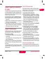
Symbols
The symbols used in this manual have the following
meanings:
English
DANGER
Indicates an imminently hazardous situation
which, if not avoided, will result in death or serious injury.
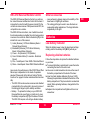
Introduction
Purchase
Congratulations on the purchase of a new Rotating
Laser from Leica Geosystems.
Product
This manual contains important safety
directions as well as instructions for
setting up the product and operating it.
Refer to "Safety Directions" for further
information.
Read carefully through the User Manual before you
switch on the product.
Product identification
The model and the serial number of your product are
indicated on the type plate.
Enter the model and serial number in your manual and
always refer to this information when you need to contact
your agency or Leica Geosystems authorized service
workshop.
Type: ____________
)
WARNING
Indicates a potentially hazardous situation or an
unintended use which, if not avoided, could result in
death or serious injury.
CAUTION
Indicates a potentially hazardous situation or an
unintended use which, if not avoided, may result in minor
or moderate injury and / or appreciable material, financial and environmental damage.
Important paragraphs which must be adhered to in
practice as they enable the product to be used in
a technically correct and efficient manner.
Trademarks
All trademarks are the property of their respective
owners.
)
Serial no.: ____________
Note: There are drawings on the first and last
page of the user manual. Unfold these pages
while reading through the User Manual. The
letters and numbers in {} always refer to these
drawings.
Introduction
1
Roteo 35 - 1.1.0en
Check your work .................................................... 13
Troubleshooting ...................................................... 14
Care and Transport.................................................. 16
Transport................................................................ 16
Storage .................................................................. 16
Cleaning and Drying .............................................. 17
Safety Directions ..................................................... 17
General .................................................................. 17
Intended Use.......................................................... 17
Limits of Use .......................................................... 18
Responsibilities ...................................................... 18
Hazards of Use ...................................................... 18
Laser Classification................................................ 21
Electromagnetic Compatibility (EMC) .................... 23
FCC Statement, Applicable in U.S......................... 23
Technical Data ......................................................... 26
International Limited Warranty............................... 27
Contents
Introduction................................................................ 1
Features................................................................... 2
Laser Overview {A} .................................................. 3
Keypad Overview {B}............................................... 3
Carrying Case Overview {C}.................................... 3
Basic Operation ......................................................... 3
How to use your Roteo 35 ....................................... 3
Button Functions...................................................... 4
Automatic / Manual modes ...................................... 5
H.I. Alert mode......................................................... 5
Rotation mode ......................................................... 5
Scanning mode........................................................ 5
Motorized Mount {D} ................................................ 6
Set-up and applications ............................................ 6
Set-up for ceiling work ............................................. 6
Set-up for layout or floor work.................................. 7
Set-up for squaring or establishing 90° angles ........ 8
Set-up for manual slopes......................................... 8
Accessories ............................................................... 9
RC-350 Remote Control .......................................... 9
RRC-350 Receiver/Remote Control ...................... 10
Other accessories.................................................. 10
Batteries ................................................................... 10
Low battery Indicator ............................................. 10
Replacing alkaline batteries................................... 10
Using rechargeable NiMH batteries....................... 11
Later recharging..................................................... 11
Check and Adjust .................................................... 11
Notes and Responsibilities .................................... 11
Checking level accuracy ........................................ 11
Checking vertical accuracy .................................... 12
Adjusting level accuracy – The X-axis ................... 12
Adjusting level accuracy – The Y-axis ................... 12
Adjusting vertical accuracy –
The Z-axis.............................................................. 13
Roteo 35 - 1.1.0en
D
EN
F
I
E
P
NL
DK
S
N
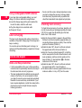
Features
The Roteo 35 laser from Leica Geosystems offers the
interior contractor many great features to make your
work easier and more accurate. A bright red beam;
motorized wall mount; small, ergonomic remote control;
optional receiver-remote control unit combine to provide
consistent value for the professional contractor.
FIN
J
CN
ROK
PL
H
RUS
CZ
2
Introduction
D
EN
F
I
E
P
NL
DK
S
N
FIN
J
CN
ROK
PL
H
RUS
CZ
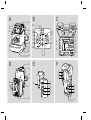
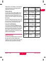
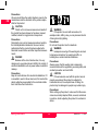
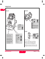
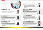
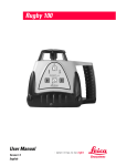
12) LED – H.I. Alert
13) LED – Low Battery
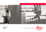
Laser Overview {A}
See the inside front cover for a diagram of the laser {A}
and keypad {B} corresponding to these callouts. See
separate descriptions of the motorized wallmount,
remote control and detector.
1) Rotating head
2) Aluminum head protection with axes indications
3) Plumb or square beam laser beam aperture
4) Rotating laser beam aperture
5) Index marks for alignment and 90°
6) Motorized wall or floor mount
7) Batteries
8) Jack for battery charger
9) 5/8"-11 Tripod mount for horizontal setup
10) 5/8"-11 Tripod mount for vertical setup
11) Sensors for remote control signal
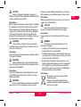
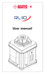
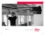
Carrying Case Overview {C}
Not all items indicated are included in the standard
package. The following identifies the locations that these
items can be placed in the carrying case.
1) Spare compartment
2) RC350 Remote Control
3) Roteo 35
4) User Manual
5) Spare Battery Holder
6) RRC350 Receiver-Remote Control (optional)
7) Ceiling Target
8) Spare D-cell Batteries
Basic Operation
Keypad Overview {B}
How to use your Roteo 35
The keypad for the Roteo laser has nine buttons and five
LED indicators.
1) Automatic / Manual Mode
2) Scan / Rotation Mode
3) On / Off
4) H.I. (Elevation) Alert
5) Motorized Mount On / Off
6) CCW Scan-Stationary Beam / Manual Slope
7) CW Scan-Stationary Beam / Manual Slope
8) Minus – Head Speed / Scan Width / Motorized Mount
9) Plus – Head Speed / Scan Width / Motorized Mount
10) LED’s – X/Y Axis Level Indicators (2) – Green (selfleveling), Red (manual)
11) LED – Motorized Mount Enabled
Basic Operation
The motorized wall mount and the metal head protection
can both be removed from the laser, if you wish to work
without these attachments.
Horizontal Setup
The laser can be mounted on a 5/8"-11 tripod or placed
directly on a solid, stable surface. It can be suspended
from a ceiling grid using the wall mount (see later
section).
Vertical Setup
The laser can be mounted on a 5/8"-11 tripod or placed
directly on its back (opposite the handle) on a solid,
3
Roteo 35 - 1.1.0en
stable surface. For more stability, it is recommended to
use the motorized mount. Use the support plate for
stability when in vertical mode.
Mode
Turning on the laser
Turn on the laser with the On/Off key {B-3}. It does a
self-test and the beam blinks while the laser is selfleveling. After it is leveled, the head rotates. You can
choose H.I. Alert mode or change to manual mode (see
later sections).
The laser has a wide self-leveling range; however, if the
laser is set up out of the leveling range, the laser beam
will continue to blink and the rotation will not start.
X-axis and Y-axis LED indicators
The X and Y-axis LED indicators {B-10} slowly blink
green while the axes are leveling and turn on solid when
each axis has reached a level position. They will rapidly
blink red when in manual mode and the axis can be
adjusted. They will be red and on solid when in manual,
but the axis cannot be adjusted.
Button Functions
The CCW/CW and Plus/Minus buttons on the laser and
the remote control units have multiple functions
depending on the mode of operation. Please refer to the
chart below to better understand their functionality.
CCW / CW Buttons Plus / Minus
Buttons
Automatic
Moves stationary
mode - rotating beam – CCW/CW
Changes head
speed
Automatic
mode - scanning
Moves scanning
beam – CCW/CW
Changes scan
width
Laydown mode Moves vertical
- rotating
plane – Left/Right
Changes head
speed
Laydown mode Moves scanning
- scanning
beam – CCW/CW
Changes scan
width
Manual mode rotating
Moves manual
slope – Inclines
plane
Changes head
speed
Manual mode scanning
Moves scanning
beam – CCW/CW
Changes scan
width
Motor mount
mode
No function
Moves the laser
- Up/Down
D
EN
F
I
E
P
NL
DK
S
N
FIN
J
CN
ROK
PL
H
RUS
CZ
Roteo 35 - 1.1.0en
4
Basic Operation
D
EN
F
I
E
P
NL
DK
S
N
FIN
J
CN
ROK
PL
H
RUS
CZ
Automatic / Manual modes
Rotation mode
The Roteo 35 is in automatic, self-leveling mode when
turned on. Once the instrument has self-leveled, the
laser head will start rotating (300 rpm).
In manual mode, the laser does not self-level; this
means that the beam will rotate even if the laser is not
leveled. It can therefore be used on inclined planes such
as stairs, roofs, or when manual grade setting is
required. See later section on setting slope in manual or
semi-automatic modes.
The head rotates at four speeds: 0, 150, 300, 450, 600
rpm. The default setting is 300 rpm. The laser beam is
more visible at slower rotation speeds.
X To increase the rotation speed press the Plus key {B9}. Press the Minus key {B-8} to decrease speed.
Press and hold the Minus key to stop rotation.
X When the beam is stopped, the point can be moved to
the right or left using the Counter-clockwise / Clockwise (CCW/CW) rotation keys {B-6 and B-7}. You can
also move the head manually to position the beam
point. To start rotation again, press the Plus key {B-9}.
H.I. Alert mode
The H.I. feature stops the laser automatically and
sounds an alarm if the laser is disturbed, preventing
inaccurate readings. It functions only when selected.
X To activate this safeguard feature, press the H.I. key
{B-4} after turning on the laser. The H.I. LED {B-12}
will blink rapidly while the laser is self-leveling.
X Thirty seconds after the head starts to rotate, the LED
will blink slowly, indicating the H.I. Alert function is
activated.
X If the laser is disturbed while in H.I. Alert mode, the
head will stop rotating, the beam will turn off, the LED
indicator will be on continuously, and an alarm will
sound.
X Press the H.I. key to turn off the H.I. Alert function.
Check to see if the beam elevation has changed from
its original benchmark position.
X The laser is no longer in H.I. Alert mode. Press the H.I.
key to re-activate the H.I. Alert function.
Basic Operation
Scanning mode
For interior applications, scanning mode allows you to
see the beam easier at a distance.
X To scan press the Scan / Rotation key {B-2}. The
beam will blink until the laser has self-leveled.
X To increase the scan length press the Plus key {B-9}.
Press the Minus key {B-8} to decrease the scan
length.
X The scanning beam can be moved to the right or left
using the Counter-clockwise / Clockwise (CCW/CW)
rotation keys {B-6 and B-7}.
5
Roteo 35 - 1.1.0en
Wait until self-leveled
While the laser is moving on the mount it does not selflevel and the beam continues to rotate.
X After moving the laser, wait a few seconds in case the
laser needs to self-level. Check that it is still on the
point or level desired and make adjustments if
needed.
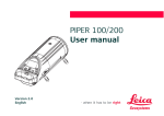
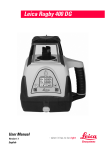
Motorized Mount {D}
See the inside, front cover for illustrations of the Motorized Wall Mount.
1) Attachment clamps for laser and mount
2) Clamp for ceiling grid
3) Adjustable plate
4) 5/8"-11 tripod mount (vertical setup)
5) Moves laser manually on mount
6) Holes for attaching mount to wall
7) Adjustable support for wall or ground stability
8) Screw to adjust support
9) Index notches for alignment
The motorized wall mount can be used to move the laser
up or down on a ceiling grid. It can also be used when
installing walls and partitions to move the laser back and
forth for vertical alignment.
Automatic exit from mode
If you have not activated the wall mount for five minutes,
the laser will automatically exit from the motorized mount
mode and return to the previous mode. The Motorized
mount LED will turn off.
Troubleshooting
X If the laser does not move on the mount, check that
the knobs {D-1} are tight enough to make the power
contact for the motor. The mount can also be
detached to check that the contacts are clean where
the laser and mount.
Activating the motorized wall mount
Allow the laser to self-level. Note the position or the
beam.
X Press the Motorized mount key {B-5} to activate the
mount. The motorized mount LED {B-11} will turn on
to indicate that the mount is now active (on the
Remote, press Scan/Rotation key {E-3, F-4} for 1.5
seconds).
X To raise the laser press the Plus key {B-9}. Press the
Minus key {B-8} to lower the laser.
Set-up and applications
Set-up for ceiling work
The Roteo 35 is perfect for the leveling of suspended
ceilings when used together with the motorized wall
mount and magnetic ceiling grid target.
To attach the laser and wall mount to the first piece
of perimeter ceiling grid:
X Flip down the support plate {D-8}
X Release the clamp {D-2} on top of the adjustable plate
{D-3}.
X Lock the clamp against the ceiling grid.
Maximum movement
When the beam is at 0 on the adjustable plate, the laser
can be raised a maximum of 50 mm (2") and lowered a
maximum of 60 mm (2.25").
Roteo 35 - 1.1.0en
6
Set-up and applications
D
EN
F
I
E
P
NL
DK
S
N
FIN
J
CN
ROK
PL
H
RUS
CZ
D
EN
F
I
E
P
NL
DK
S
N
FIN
J
CN
ROK
X If the foot on the support plate is not touching the wall,
Set-up for layout or floor work
use the screw {D-9} to adjust.
The Roteo 35 can easily be used in the laydown or
vertical mode for laying out walls locations, transferring
points from the floor to the ceiling and plumb applications.
To move the laser up or down:
X Turn on the laser and wait for it to self-level. The head
must be rotating before you can enter motorized
mount mode.
X Press the motorized mount key {B-5} to activate the
mount. The motorized mount LED {B-11} will turn on
to indicate that the mount is now active.
X To raise the motorized mount press the Plus key {B9}. Press the Minus key {B-8} to lower motorized
mount. Holding the key will result in fast movement;
short clicks will move the laser more precisely.
To use the laser in the vertical mode:
X Flip down the support plate {D-8} and place the laser
in vertical mode on the floor.
X If the support plate is not level, use the screw {D-9} to
adjust.
X Set up the laser over a control point by first pointing
the stationary beam downward, and then manually, or
by using the motorized mount, move the laser over the
reference mark.
X Adjust the rotating or scanning beam to a second
control point to establish the desired vertical plane.
For fine adjustments, use the CCW/CW {B-6 and B7} buttons to move the beam left and right.
X Once the laser is adjusted to the two reference marks,
points can easily be transferred from the floor to the
ceiling for the construction of walls.
X This type of set up is an excellent application of the
use of the remote control unit. Use the remote while
monitoring the beam until it is in line with the second
control point. See illustration {H} in the back, inside
cover of this manual.
Getting to work:
X Raise the laser on the motorized mount until the
rotating beam is at the same level as the perimeter
ceiling grid. Use the line created by the laser as a
reference to attach the perimeter grid to the wall.
X Lower the laser on the motorized mount until the
rotating beam is striking the on-grade position on the
magnetic, ceiling grid target.
X Adjust the height of the ceiling grid using the laser
beam on the target as your reference. See illustration
{G} in the back, inside cover of this manual.
PL
H
RUS
CZ
Set-up and applications
7
Roteo 35 - 1.1.0en
Set-up for full manual mode
Set-up for squaring or establishing
90° angles
In full manual mode, the unit will not self-level and the
head will continue to rotate. The plane of laser light can
be tilted in either one or both planes.
The Roteo 35 has a plumb beam that projects from the
top of the rotating head. This beam is projected at a 90°
angle to the main beam. This feature allows the laser to
be used for laying out floor plans.
To use the laser in full manual mode:
X After turning the laser on and allowing it to self-level,
press the Auto/Manual key {B-1}. The X-axis LED {B10} above the key will blink red rapidly, indicating that
you are in manual mode and you can set slope in the
X-axis. (The Y-axis LED will also be on and red.)
X Turn the laser so that the X on the top of the laser
faces the direction of the slope.
X Press either CCW/CW (manual slope) keys {B-6 or B7} to adjust the slope of the X-axis.
X To adjust the slope of the Y-axis, press the Auto/
Manual key {B-1} again. The Y-axis LED {B-10}
above the key will blink red rapidly, indicating that you
are in manual mode and you can set slope in the Yaxis. (The X-axis LED will also be on and red.)
X Turn the laser so that the Y on the top of the laser
faces the direction of the slope.
X Press either CCW/CW (manual slope) keys {B-6 or B7} to adjust the slope of the Y-axis.
X Press the Auto/Manual key {B-1} for 1.5 seconds to
exit manual mode and return to automatic mode. See
illustration {J} in the back, inside cover of this manual.
To use the laser to square or establish 90° angles:
X Follow exactly the same set up procedure above for
layout work.
X Align the laser to two reference points using either the
main beam or the top plumb beam.
X Once aligned, the two beams create an accurate 90°
angle for wall layout and construction. See illustration
{I} in the back, inside cover of this manual.
Set-up for manual slopes
The Roteo 35 can be used to manually create slopes for
special applications, stairways, sloped ceilings, etc.
Two modes are available:
• Full manual mode – Both the X and Y-axes will be in
manual mode
• Semi-automatic mode – The X-axis self-levels, The Yaxis is in manual mode.
For slopes up to 10%, set up the laser in horizontal mode
and use the remote to set the slope following the instructions below.
For slopes greater than 10%, set up the laser in vertical
mode and use the inclined plane feature explained in the
following section.
Roteo 35 - 1.1.0en
Set-up for semi-automatic mode
In semi-automatic mode, the unit will self-level in the Xaxis. The plane of laser light can be tilted manually in the
Y-axis.
8
Set-up and applications
D
EN
F
I
E
P
NL
DK
S
N
FIN
J
CN
ROK
PL
H
RUS
CZ
D
EN
F
I
E
P
NL
DK
S
N
FIN
J
CN
ROK
PL
H
RUS
To use the laser in semi-automatic mode:
X After turning the laser on and allow the laser to selflevel, press and hold the Auto/Manual key {B-1} for
three seconds. The X-axis LED {B-10} above the key
will blink green slowly while leveling. The Y-axis LED
will blink quickly indicating that the Y-axis is in manual
mode and you can set slope in the Y-axis.
X Turn the laser so that the Y on the top of the laser
faces the direction of the slope.
X Press either CCW/CW (manual slope) keys {B-6 or B7} to adjust the slope of the Y-axis.
X Press the Auto/Manual key {B-1} again to exit semiautomatic mode and return to automatic mode.
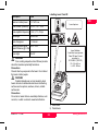
Accessories
RC-350 Remote Control
The RC-350 Remote Control has five buttons which
perform the same function as the buttons on the laser.
Refer to illustration {E} on the inside front cover of this
manual.
1) CCW Scan-Stationary Beam / Manual Slope
2) CW Scan-Stationary Beam / Manual Slope
3) Scan / Rotation Mode (1.5 seconds - Motorized
Mount)
4) Plus – Head Speed / Scan Width / Motorized Mount
5) Minus – Head Speed / Scan Width / Motorized Mount
Set-up for inclined planes
The Roteo 35 can also be tilted, for manual slope, at
various angles on the wall mount. A tripod with rotating
mounting plate will speed set-up.
The performance of CCW/CW and Plus/Minus keys is
dependent on the mode of operation selected. Please
refer to the table in "Button Functions" on page 4 to
better understand their functionality.
• The red LED at the top of the remote will flash each
time a button is pressed, indicating that the remote is
transmitting to the laser.
• Battery – To open the battery compartment {E-6} and
change the battery, push the battery cover in the
direction of the arrow. The RC-350 requires one AA
alkaline battery.
To use the laser for inclined planes:
X Set the laser in vertical mode, preferably on a tripod.
If setting on the ground, flip down the support plate for
stability.
X After the laser has self-leveled, set in manual or semiautomatic mode.
X Loosen the knobs on either side {D-1} to partially
separate the mount from the laser.
X Move the laser to the approximate inclined position
and tighten slightly.
X Move to the final position and tighten further. See illustration {K} in the back, inside cover of this manual.
CZ
Accessories
9
Roteo 35 - 1.1.0en
D
RRC-350 Receiver/Remote Control
Other accessories
The RRC-350 Receiver/Remote Control is a combination Laser Receiver and Remote Control for the laser. It
is important to note that with the power turned ON, the
unit acts as a laser receiver. With power turned OFF, the
unit performs as a remote.
The RRC-350 has six buttons; two of which have dual
functions depending on whether the unit is being used as
a receiver or as a remote. Refer to illustration {F} on the
inside front cover of this manual.
1) Audio (Receiver), CW Scan-Stationary Beam /
Manual Slope (Remote)
2) Bandwidth (Receiver), CCW Scan-Stationary
Beam / Manual Slope (Remote)
3) Power – On (Receiver) / Off (Remote)
4) Scan / Rotation Mode (1.5 seconds - Motorized
Mount)
5) Plus – Head Speed / Scan Width / Motorized Mount
6) Minus – Head Speed / Scan Width / Motorized Mount
• Laser enhancing glasses improve the visibility of the
laser beam in bright light conditions.
• The ceiling grid target is used to view the beam on
suspended ceiling applications. The target attaches
magnetically to the grid.
As a remote, the performance of the CCW/CW and Plus/
Minus keys is dependent on the mode of operation
selected. Please refer to the table in Section "Button
Functions" on page 4 to better understand their functionality.
• The RRC-350 can be used as a receiver and attached
magnetically to the ceiling grid to be used in place of
the ceiling grid target in poor visibility conditions.
• Battery – To replace the battery on your RRC-350
Receiver/Remote use a finger or small coin to open
the battery compartment {F-7} at the base of the unit.
The RRC-350 requires a 9-volt type alkaline battery.
Roteo 35 - 1.1.0en
10
EN
F
I
E
Batteries
P
Low battery Indicator
NL
When the battery power is low, the laser head will stop
rotating and the low battery LED {B-13} will stay on.
DK
S
Replacing alkaline batteries
Follow the steps below to replace the alkaline batteries
in your laser.
X To access the battery compartment, loosen the knobs
connecting the laser to the wall mount.
X Use a coin or small screwdriver to remove the cover of
the battery compartment at the back of the laser.
X Insert two fresh alkaline batteries (D size or LR20),
following the polarization indicated at the bottom of the
battery compartment. The plus contact is rounded and
raised. When replacing batteries, change both at the
same time.
X Replace the compartment and tighten with a coin or
screwdriver.
N
FIN
J
CN
ROK
PL
H
RUS
CZ
Batteries
D
Using rechargeable NiMH batteries
EN
If your laser has a rechargeable battery, you must
charge it for 8 hours before first using the laser.
X Insert the charger plug into the jack located at the
back of the laser, under the wall mount.
X Plug the charger into an electrical outlet.
X Charge for 8 hours.
F
I
E
P
NL
DK
S
N
FIN
J
CN
ROK
PL
H
RUS
CZ
• Do not enter this mode or attempt adjustment unless
you plan to change the accuracy. Accuracy adjustment should only be performed by a qualified individual that understands basic adjustment principles.
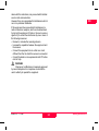
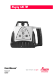
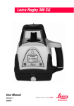
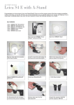
Checking level accuracy
To check the level accuracy of your laser, place the unit
on a flat, level surface or tripod approximately 30 meters
(100 ft.) from a wall. See illustration {L} in the back,
inside cover of this manual.
X Align the X-axis so that it is square to the wall. Allow
the laser to self-level completely (approximately one
minute after the laser begins to rotate). Then mark the
position of the beam (Position 1).
X Rotate the laser 180°, allow it to self level and mark
the opposite side of the first axis (Position 2).
X Align the Y-axis by rotating the laser 90° so that this
axis is now square to the wall. Allow the laser to selflevel completely, and then mark the position of the
beam (Position 3). See illustration {M} in the back,
inside cover of this manual.
X Rotate the laser 180°, allow it to self level and mark
the opposite side of the Y-axis (Position 4).
X The laser is within its accuracy specification if the four
marks are within ± 3 mm (± 1/8") from the center.
Later recharging
The laser can be charged while working if electricity is
available on the jobsite. Simply plug in the charger and
keep on working.
You can also remove the battery pack to charge it, or
replace it with the alkaline battery compartment to keep
on working.
Check and Adjust
Notes and Responsibilities
• It is the responsibility of the user to follow operating
instructions and to periodically check the accuracy of
the instrument and work as it progresses.
• The laser is adjusted to the defined accuracy specifications at the factory. It is recommended to check
your laser for accuracy upon receipt and periodically
thereafter to ensure accuracy is maintained. If your
laser requires adjustment, contact the nearest authorized service center or adjust the laser using the
following procedure.
Check and Adjust
11
Roteo 35 - 1.1.0en
Checking vertical accuracy
To check the vertical accuracy of your laser, place the
unit in the laydown position on a flat, level surface
approximately 15-30 meters (50-100 ft.) from a wall. See
illustration {N} in the back, inside cover of this manual.
X Hang a plumb line on the wall.
X Move the laser until the vertical, rotating beam is
aligned to the plumb line.
X If the rotating beam is not plumb, adjustment is necessary.
Adjusting level accuracy – The X-axis
After checking the accuracy of your laser, perform the
following steps to adjust the accuracy of the X-axis.
X Turn off the laser.
X Press and hold the Auto/Manual key {B-1}, then press
the On/Off key {B-3}.
X After the X and Y LED’s blink three times simultaneously, release the Auto/Manual key.
• The X-axis LED will flash rapidly (red) while
leveling.
• The X-axis LED will flash slowly (red) when ready
for adjustment.
• The head will not be rotating.
• To use a receiver, press the Scan/Rotation key {B2} to start rotation mode.
X Press a CCW/CW key {B-6 or B-7} to adjust the beam
up or down. Five presses of the key will move the
beam approximately 1.5 mm at 30 meters (1/16" at
100 feet). Use of the remote for this adjustment will
make the job easier by not disturbing the laser.
Roteo 35 - 1.1.0en
12
After completing the changes to the X-axis, do one
of the following steps:
X Press the Plus key {B-9} after completing adjustment
to switch to the Y-axis.
X Press the Minus key {B-8} to exit adjustment mode,
save changes and turn off the laser.
X Press the On/Off key {B-3} at any time to turn off the
laser without saving any changes.
D
EN
F
I
E
Adjusting level accuracy – The Y-axis
P
After checking the accuracy of your laser, perform
the following steps to adjust the accuracy of the Yaxis.
X If already in adjustment mode for the X-axis, press the
Plus key {B-9} to switch to the adjustment of the Yaxis.
X If not in adjustment mode, follow the steps above for
entering adjustment mode, then press the Plus key to
switch to the adjustment of the Y-axis.
• The Y-axis LED will flash rapidly (red) while
leveling.
• The Y-axis LED will flash slowly (red) when ready
for adjustment.
• The head will not be rotating.
• To use a receiver, press the Scan/Rotation key {B2} to start rotation mode.
X Press a CCW/CW key {B-6 or B-7} to adjust the beam
up or down. Five presses of the key will move the
beam approximately 1.5 mm at 30 meters (1/16" at
100 feet). Use of the remote for this adjustment will
make the job easier by not disturbing the laser.
NL
Check and Adjust
DK
S
N
FIN
J
CN
ROK
PL
H
RUS
CZ
D
EN
F
I
E
P
NL
DK
S
N
FIN
J
CN
ROK
PL
H
RUS
CZ
After completing the changes to the Y-axis, do one
of the following steps:
X Press the Minus key {B-8} to exit adjustment mode,
save changes and turn off the laser.
X Press the On/Off key {B-3} at any time to turn off the
laser without saving any changes.
After completing the changes to the Z-axis, do one
of the following steps:
X Press the Minus key {B-8} to exit adjustment mode,
save changes and turn off the laser.
X Press the On/Off key {B-3} at any time to turn off the
laser without saving any changes.
Adjusting vertical accuracy –
The Z-axis
Check your work
After any accuracy adjustments always double check
your work, by making a final check of the laser.
After checking the vertical accuracy of your laser,
perform the following steps to adjust the Z-axis.
X Turn off the laser.
X Place the laser in the laydown position approximately
6 meters (20 feet) from a plumb line on a wall.
X Press and hold the Auto/Manual key {B-1}, then press
the On/Off key {B-3}.
X After the X and Y LED’s blink three times simultaneously, release the Auto/Manual key.
• The Z-axis (Y-axis) LED will flash rapidly (red) while
leveling.
• The Z-axis (Y-axis) LED will flash slowly (red) when
ready for adjustment.
• The head will not be rotating.
• To use a receiver, press the Scan/Rotation key {B2} to start rotation mode.
X Press a CCW/CW key {B-6 or B-7} to adjust the beam
to the plumb line. Twenty-five presses of the key will
move the beam approximately 1.5 mm at 6 meters (1/
16" at 20 feet). Use of the remote for this adjustment
will make the job easier by not disturbing the laser.
Check and Adjust
13
Roteo 35 - 1.1.0en
D
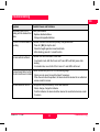
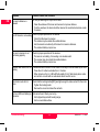
Troubleshooting
EN
Possible Causes and Solutions
F
Check your batteries
Low battery LED is on or
flashing and the head will not • Replace alkaline batteries.
rotate.
• Charge rechargeable batteries.
I
Symptom
E
P
H.I. Alert is on and an alarm is The laser has been disturbed and possibly changed elevation.
sounding.
• Press H.I. {B-5} to stop the alert.
• Check the height against a known benchmark.
• After checking, press H.I. to reset function.
The laser will not self-level
NL
DK
The laser must be in automatic to self-level.
• In automatic mode, both the X-axis and Y-axis LED’s will blink green while
leveling.
• In manual mode, one or both of the X-axis or Y-axis LED’s will be red.
The laser beam blinks, but the The unit is most likely out of its 10% self-leveling range.
unit will not self-level or rotate. • Check your set up and re-level the tripod if necessary.
• If this does not solve the problem, the laser should be returned to an authorized
service center for service.
The laser does not turn on
The symptom may be caused by low or dead batteries.
• Check, change, charge the batteries.
• If not the batteries, the laser should be returned to an authorized service center
for service.
S
N
FIN
J
CN
ROK
PL
H
RUS
CZ
Roteo 35 - 1.1.0en
14
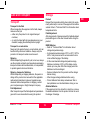
Troubleshooting
D
EN
F
Symptom
Possible Causes and Solutions
The laser’s distance is
reduced
Dirt may be reducing the output of the laser.
• Clean the windows of the laser and receiver to improve distance.
• If not the windows, the laser should be returned to an authorized service center
for service.
I
E
P
NL
DK
S
The IR Remote is not working Check for proper operation of the remote.
• Check that the laser is turned on.
• The remote may be outside the usable distance.
• Aim the remote more directly at the laser for maximum distance.
• The remote’s battery may be low.
The laser’s receiver is not
functioning properly.
N
FIN
J
CN
ROK
Elevation alert function is not The elevation alert function for the Roteo is normally off until activated by the user.
working
• Press the H.I. button to activate the H.I. function.
• When turned on, the H.I. LED will flash rapidly (5 Hz), flash slowly when active,
and will turn on solid with an audio alarm when an alert occurs.
Motorized mount will not
move.
PL
H
RUS
Check for proper operation of the receiver.
• The laser is not rotating. It is leveling or in elevation alert.
• The receiver may be outside the usable distance.
• The remote’s battery may be low.
Check that the locking knobs {D-1} are tight enough to make contact for the motor.
• Tighten the locking knobs.
• Remove the mount and clean the contacts.
Top four LED's are flashing in Unit cannot level. Check your set up.
sequence.
• Unit is tipped beyond self-leveling range.
• Unit is on unstable surface.
CZ
Troubleshooting
15
Roteo 35 - 1.1.0en
Transport
Transport in the field
When transporting the equipment in the field, always
make sure that you
• either carry the product in its original transport
container,
• or carry the tripod with its legs splayed across your
shoulder, keeping the attached product upright.
Product
Respect the temperature limits when storing the equipment, particularly in summer if the equipment is inside a
vehicle. Refer to "Technical Data" for information about
temperature limits.
EN
Field Adjustment
After long periods of storage inspect the field adjustment
parameters given in this user manual before using the
product.
E
NiMH Batteries
• Refer to "Technical Data" for information about
storage temperature range.
• A storage temperature range of 0°C to +20°C / 32°F to
68°F in a dry environment is recommended to minimize self-discharging of the battery.
• At the recommended storage temperature range,
batteries containing a 10% to 50% charge can be
stored up to one year. After this storage period the
batteries must be recharged.
• Remove batteries from the product and the charger
before storing.
• After storage recharge batteries before using.
• Protect batteries from damp and wetness. Wet or
damp batteries must be dried before storing or use.
Transport in a road vehicle
Never carry the product loose in a road vehicle, as it can
be affected by shock and vibration. Always carry the
product in its transport container and secure it.
Shipping
When transporting the product by rail, air or sea, always
use the complete original Leica Geosystems packaging,
transport container and cardboard box, or its equivalent,
to protect against shock and vibration.
Shipping, transport of batteries
When transporting or shipping batteries, the person in
charge of the product must ensure that the applicable
national and international rules and regulations are
observed. Before transportation or shipping, contact
your local passenger or freight transport company.
Alkaline Batteries
If the equipment is to be stored for a long time, remove
the alkaline batteries from the product in order to avoid
the danger of leakage.
Field Adjustment
After transport inspect the field adjustment parameters
given in this user manual before using the product.
Roteo 35 - 1.1.0en
D
Storage
Care and Transport
16
Care and Transport
F
I
P
NL
DK
S
N
FIN
J
CN
ROK
PL
H
RUS
CZ
D
EN
F
I
E
P
NL
DK
S
N
FIN
J
CN
ROK
PL
H
RUS
CZ
The person responsible for the product must ensure that
all users understand these directions and adhere to
them.
Cleaning and Drying
Product and Accessories
• Blow dust off optical parts.
• Never touch the glass with your fingers.
• Use only a clean, soft, lint-free cloth for cleaning. If
necessary, moisten the cloth with water or pure
alcohol.
• Do not use other liquids; these may attack the polymer
components.
Intended Use
Permitted Use
• The instrument casts a horizontal laser plane for the
purposes of alignment.
• The unit can be set up on it’s own base plate, wallmount or on a tripod.
• The laser beam can be detected by means of a laser
detector.
• This product is intended for indoor use and applications.
Damp Products
• Dry the product, the transport container, the foam
inserts and the accessories at a temperature not
greater than 40°C / 104°F and clean them.
• Do not repack until everything is completely dry.
Adverse Use
• Use of the product without instruction.
• Use outside of the intended limits.
• Disabling safety systems.
• Removal of hazard notices.
• Opening the product using tools, for example screwdriver, unless this is specifically permitted for certain
functions.
• Modification or conversion of the product.
• Use after misappropriation.
• Use of products with obviously recognizable damages
or defects.
• Use with accessories from other manufacturers
without the prior explicit approval of Leica Geosystems.
• Inadequate safeguards at the work site, for example
when using on or near roads.
Cables and Plugs
• Keep plugs clean and dry.
• Blow away any dirt lodged in the plugs of the
connecting cables.
Safety Directions
General
Description
The following directions should enable the person
responsible for the product, and the person who actually
uses the equipment, to anticipate and avoid operational
hazards.
Safety Directions
17
Roteo 35 - 1.1.0en
Manufacturers of non Leica Geosystems accessories
The manufacturers of non Leica Geosystems accessories for the product are responsible for developing,
implementing and communicating safety concepts for
their products, and are also responsible for the effectiveness of those safety concepts in combination with the
Leica Geosystems product.
• Deliberate dazzling of third parties.
• Controlling of machines, moving objects or similar
monitoring application without additional control and
safety installations.
WARNING
Adverse use can lead to injury, malfunction and
damage. It is the task of the person responsible for the
equipment to inform the user about hazards and how to
counteract them. The product is not to be operated until
the user has been instructed on how to work with it.
Limits of Use
Environment
Suitable for use in an atmosphere appropriate for permanent human habitation: not suitable for use in aggressive
or explosive environments.
DANGER
Local safety authorities and safety experts must
be contacted before working in hazardous areas, or in
close proximity to electrical installations or similar situations by the person in charge of the product.
WARNING
The person responsible for the product must
ensure that it is used in accordance with the instructions.
This person is also accountable for the training and the
deployment of personnel who use the product and for
the safety of the equipment in use.
Responsibilities
Hazards of Use
Manufacturer of the product
Leica Geosystems AG, CH-9435 Heerbrugg, hereinafter
referred to as Leica Geosystems, is responsible for
supplying the product, including the user manual and
original accessories, in a completely safe condition.
Roteo 35 - 1.1.0en
Person in charge of the product
The person in charge of the product has the following
duties
• To understand the safety instructions on the product
and the instructions in the user manual.
• To be familiar with local regulations relating to safety
and accident prevention.
• To inform Leica Geosystems immediately if the
product and the application becomes unsafe.
EN
F
I
E
P
NL
DK
S
N
FIN
J
CN
ROK
PL
WARNING
The absence of instruction, or the inadequate
imparting of instruction, can lead to incorrect or adverse
use, and can give rise to accidents with far-reaching
human, material, financial and environmental consequences.
18
D
Safety Directions
H
RUS
CZ
D
EN
F
I
E
P
NL
DK
S
N
FIN
J
CN
ROK
Precautions:
All users must follow the safety directions given by the
manufacturer and the directions of the person responsible for the product.
CAUTION
Watch out for erroneous measurement results if
the product has been dropped or has been misused,
modified, stored for long periods or transported.
WARNING
If the product is used with accessories, for
example masts, staffs, poles, you may increase the risk
of being struck by lightning.
Precautions:
Periodically carry out test measurements and perform
the field adjustments indicated in the user manual,
particularly after the product has been subjected to
abnormal use and before and after important measurements.
Precautions:
Do not use the product in a thunderstorm.
WARNING
Inadequate securing of the working site can lead
to dangerous situations, for example in traffic, on
building sites, and at industrial installations.
DANGER
Because of the risk of electrocution, it is very
dangerous to use grade rods and staffs in the vicinity of
electrical installations such as power cables or electrical
railways.
Precautions:
Always ensure that the working site is adequately
secured. Adhere to the regulations governing safety and
accident prevention and road traffic.
Precautions:
Keep at a safe distance from electrical installations. If it
is essential to work in this environment, first contact the
safety authorities responsible for the electrical installations and follow their instructions.
CAUTION
If the accessories used with the product are not
properly secured and the product is subjected to
mechanical shock, for example blows or falling, the
product may be damaged or people may sustain injury.
PL
Precautions:
When setting-up the product, make sure that the accessories are correctly adapted, fitted, secured, and locked
in position. Avoid subjecting the product to mechanical
stress.
H
RUS
CZ
Safety Directions
19
Roteo 35 - 1.1.0en
CAUTION
During the transport, shipping or disposal of
batteries it is possible for inappropriate mechanical influences to constitute a fire hazard.
Precautions:
Before shipping the product or disposing of it, discharge
the batteries by running the product until they are flat.
When transporting or shipping batteries, the person in
charge of the product must ensure that the applicable
national and international rules and regulations are
observed. Before transportation or shipping contact your
local passenger or freight transport company.
D
Precautions:
Make sure that the battery terminals do not come into
contact with metallic objects.
EN
CAUTION
During the operation of the product there is a
hazard of squeezing extremities by moving parts.
Precautions:
Keep extremities in a safe distance from the moving
parts.
WARNING
If the product is improperly disposed of, the
following can happen:
• If polymer parts are burnt, poisonous gases are
produced which may impair health.
• If batteries are damaged or are heated strongly, they
can explode and cause poisoning, burning, corrosion
or environmental contamination.
• By disposing of the product irresponsibly you may
enable unauthorized persons to use it in contravention
of the regulations, exposing themselves and third
parties to the risk of severe injury and rendering the
environment liable to contamination.
WARNING
Using a battery charger not recommended by
Leica Geosystems can destroy the batteries. This can
cause fire or explosions.
Precautions:
Only use chargers recommended by Leica Geosystems
to charge the batteries.
WARNING
High mechanical stress, high ambient temperatures or immersion into fluids can cause leackage, fire or
explosions of the batteries.
Precautions:
Protect the batteries from mechanical influences and
high ambient temperatures. Do not drop or immerse
batteries into fluids.
Precautions
The product must not be disposed with
household waste.
Dispose of the product appropriately in
accordance with the national regulations in
force in your country.
WARNING
Short circuited battery terminals can overheat and
cause injury or fire, for example by storing or trans-
Roteo 35 - 1.1.0en
porting in pockets if battery terminals come in contact
with jewellery, keys, metallized paper or other metals.
20
Safety Directions
F
I
E
P
NL
DK
S
N
FIN
J
CN
ROK
PL
H
RUS
CZ
D
EN
F
I
E
P
NL
DK
S
N
FIN
J
CN
ROK
PL
H
RUS
CZ
Products classified as laser class 2 or class 3R may
cause dazzle, flash blindness and afterimages, particularly under low ambient light conditions.
Always prevent access to the product by unauthorized
personnel.
Product specific treatment and waste management
information can be downloaded from the Leica Geosystems home page at http://www.leica-geosystems.com/
treatment or received from your Leica Geosystems
dealer.
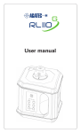
Roteo 35
The rotating laser produces a visible red laser beam
which emerges from the rotating head.
WARNING
Only Leica Geosystems authorized service workshops are entitled to repair these products.
The laser product with a stationary rotating head is classified as laser class 3R in accordance with *):
• IEC 60825-1 (2007-03): “Safety of laser products”.
*) Class 2 product if head is rotating.
Laser Classification
General
The following directions (in accordance with the state of
the art - international standard IEC 60825-1 (2007-03)
and IEC TR 60825-14 (2004-02)) provide instruction and
training information to the person responsible for the
product and the person who actually uses the equipment, to anticipate and avoid operational hazards.
The person responsible for the product must ensure that
all users understand these directions and adhere to
them.
Products classified as laser class 1, class 2 and class 3R
do not require
• laser safety officer involvement,
• protective clothes and eyewear,
• special warning signs in the laser working area
if used and operated as defined in this user manual due
to the low eye hazard level.
Safety Directions
Class 3R laser products:
Direct intrabeam viewing may be hazardous (low level
eye hazard), in particular for deliberate ocular exposure.
The risk of injury for laser class 3R products is limited
because of:
a) unintentional exposure would rarely reflect worst
case conditions of (e.g.) beam alignment with the
pupil, worst case accomodation.
b) inherent safety margin in the maximum permissible
exposure to laser radiation (MPE)
c) natural aversion behaviour for exposure to bright light
for the case of visible radiation.
21
Roteo 35 - 1.1.0en
Description
Value
Maximum radiant power
< 2.7 mW c.w.
Pulse duration (effective)
4.5, 2.2, 1.5, 1.1 ms
Labelling, Laser Class 3R
D
EN
Laser Aperture
F
Pulse repetition frequency 0, 2.5, 5, 7.5, 10 rps
I
Wavelength
620-690 nm
E
Beam divergence
< 1.5 mrad
P
NOHD (Nominal Ocular
35 m / 115 ft
Hazard Distance) @ 0.25s
Scan angle
NL
2 to 36°
WARNING
From a safety perspective class 3R laser products
should be treated as potentially hazardous.
2
Precautions:
Prevent direct eye exposure to the beam. Do not direct
the beam at other people.
Laser Radiation
Avoid direct eye exposure
Class 3R Laser Product
according to
IEC 60825-1 (2007-03)
P0 ≤ 2.4 mW c.w.
λ = 620 - 690 nm
S
N
FIN
J
CN
WARNING
Potential hazards are not only related to direct
beams but also to reflected beams aimed at reflecting
surfaces such as prisms, windows, mirrors, metallic
surfaces etc.
ROK
1
PL
H
Precautions:
Do not aim at areas that are essentially reflective, such
as mirror, or which could emit unwanted reflections.
RUS
CZ
1) Laser beam
2) Plumb beam
Roteo 35 - 1.1.0en
DK
22
Safety Directions
D
Electromagnetic Compatibility (EMC)
EN
Description
The term Electromagnetic Compatability is taken to
mean the capability of theproduct to function smoothly in
an environment where electromagnetic radiation and
electrostatic discharges are present, and without
causing electromagnetic disturbances to other equipment.
F
I
E
P
NL
DK
S
N
FIN
J
CN
ROK
PL
H
RUS
CZ
Although the product meets the strict regulations and
standards whichin this respect, Leica Geosystems
cannot completely exclude the possibility product may
be disturbed by very intense electromagnetic radiation,
near radio transmitters, two-way radios or diesel generators.
Precautions:
Check the plausibility of results obtained under these
conditions.
Precautions:
While the product is in use, connecting cables, for
example product to external battery, product to
computer, must be connected at both ends.
WARNING
Electromagnetic radiation can cause disturbances
in other equipment.
Although the product meets the strict regulations and
standards which are in force in this respect, Leica
Geosystems cannot completely exclude the possibility
that other equipment may be disturbed.
WARNING
If the product is operated with connecting cables
attached at one of their two ends, for example, external
supply cables, interface cables, the permitted level of
electromagnetic radiation may be exceeded and the
correct functioning of other products may be impaired.
CAUTION
There is a risk that disturbances may be caused in
other equipment if the product is used in conjunction with
accessories from other manufacturers, for example field
computers, personal computers, two-way radios, nonstandard cables or external batteries.
FCC Statement, Applicable in U.S.
WARNING
This equipment has been tested and found to
comply with the limits for a Class B digital device,
pursuant to part 15 of the FCC rules.
These limits are designed to provide reasonable protection against harmful interference in a residential installation.
This equipment generates, uses and can radiate
frequency energy and, if not installed and used in accor-
Precautions:
Use only the equipment and accessories recommended
by Leica Geosystems. When combined with the product,
they meet the strict requirements stipulated by the guidelines and standards. When using computers and twoway radios, pay attention to the information about electromagnetic compatibility provided by the manufacturer.
CAUTION
Disturbances caused by electromagnetic radiation can result in erroneous measurements.
Safety Directions
23
Roteo 35 - 1.1.0en
dance with the instructions, may cause harmful interference to radio communication.
However, there is no guarantee that interference will not
occur in a particular installation.
If this equipment does cause harmful interference to
radio or television reception, which can be determined
by turning the equipment off and on, the user is encouraged to try to correct the interference by one or more of
the following measures:
• Reorient or relocate the receiving antenna.
• Increase the separation between the equipment and
the receiver.
• Connect the equipment into an outlet on a circuit
different from that to which the receiver is connected.
• Consult the dealer or an experienced radio/TV technician for help.
D
EN
F
I
E
P
NL
DK
S
N
WARNING
Changes or modifications not expressly approved
by Leica Geosystems for compliance could void the
user's authority to operate the equipment.
FIN
J
CN
ROK
PL
H
RUS
CZ
Roteo 35 - 1.1.0en
24
Safety Directions
D
Labeling Roteo 35
EN
F
Roteo 35
RRC350
I
E
P
Type: RRC350
Art.No.: 762771
Power: 9.0V / 0.2A
Leica Geosystems AG
CH-9435 Heerbrugg
Manufactured:
S.No.:
Made in China
NL
DK
Type: MWM 350
S
Leica Geosystems AG
CH-9435 Heerbrugg
Manufactured:
S.No.:
Made in China
N
Art.No.:
762769
FIN
RC350
J
CN
ROK
PL
H
This device complies with part 15 of the FCC Rules.
Operation is subject to the following two conditions:
(1) This device may not cause harmful interference,
and (2) this device must accept any interference
received, including interference that may cause
undesired operation.
Type: RC350
Complies with 21CFR 1040.10 and 1040.11
except for deviations pursuant to
Laser Notice No.50, dated July 26, 2001.
This device complies with part 15 of the
FCC Rules. Operation is subject to the
following two conditions: (1) This device
may not cause harmful interference, and (2)
this device must accept any interference
received, including interference that may
cause undesired operation.
Art.No.: 762770
Type: Roteo 35
Power: 1.5V / 0.4A
Leica Geosystems AG
CH-9435 Heerbrugg
Manufactured:
Art.No.: 762768
Power: 3.0V / 1.5A
Leica Geosystems AG
CH-9435 Heerbrugg
Manufactured:
S.No.:
Made in China
FCC Part 15 Statement:
This device complies with part 15 of the FCC Rules.
Operation is subject to the following two conditions:
(1) This device may not cause harmful interference,
and (2) this device must accept any interference received,
including interference that may cause undesired operation.
RUS
CZ
Safety Directions
25
Roteo 35 - 1.1.0en
RC-350 IR Remote Control
Technical Data
Roteo 35
up to 30 m (100 ft)
Batteries
one AA alkaline battery***
Operating Range
(rotating beam)
300 m (1000 ft) Diameter, with
receiver
Self-leveling Accuracy*
±3 mm at 30 m
(±1/8" at 100 ft)
Self-leveling Range
± 4.5°
Rotation Speeds
0, 150, 300, 450, 600 rpm
Input voltage
7.5 VDC
Scanning Angle
variable from 2 to 36°
Input current
1.0 A
Laser Diode Type
635 nm (visible)
Charge time
8 hrs
Dimensions (HWD)
189 x 136 x 208 mm
(7.4 x 5.4 x 8.2")
Weight with Batteries
1.7 kg (3.7 lbs)
Batteries
Two alkaline D-cells*** /
NiMH Pack
Battery life - alkaline /
NiMH**
160 hours / 50 hours
RRC-350 IR Remote Receiver Control
Batteries
-20 to +70°C (-4 to +158°F)
Protection against
water
IP54
Roteo 35 - 1.1.0en
a 9-volt type alkaline battery***
NiMH Battery Pack
EN
F
I
E
P
NL
DK
S
NiMH Charger/Adapter
Input voltage
100-240 VAC, 55-60 Hz
Output voltage
7.5 VDC
Output current
1.0 A
Polarity
Shaft - neg, Tip - pos
N
FIN
J
* Accuracy is defined at 25°C
** Battery life is dependent upon environmental conditions
*** Leakage proof alkaline batteries strongly recommended
Operating temperature -10 to +50°C (14 to +122°F)
Storage temperature
(without batteries)
D
IR Remote range
CN
ROK
PL
H
RUS
CZ
26
Technical Data
D
EN
F
I
E
P
NL
DK
International Limited Warranty
This product is subject to the terms and conditions set
out in the International Limited Warranty which you can
download from the Leica Geosystems home page at
http://www.leica-geosystems.com/internationalwarranty
or collect from your Leica Geosystems distributor. The
foregoing warranty is exclusive and is in lieu of all other
warranties, terms or conditions, express or implied,
either in fact or by operation of law, statutory or otherwise, including warranties, terms or conditions of
merchantability, fitness for a particular purpose, satisfactory quality and non-infringement, all of which are
expressly disclaimed.
S
N
FIN
J
CN
ROK
PL
H
RUS
CZ
International Limited Warranty
27
Roteo 35 - 1.1.0en
Ask your local Leica dealer for more information about our TQM program.
Leica Geosystems AG
Heinrich-Wild-Strasse
CH-9435 Heerbrugg
Switzerland
Phone +41 71 727 31 31
www.leica-geosystems.com
Copyright Leica Geosystems AG, Heerbrugg,
Switzerland 2008
Leica Geosystems AG, Heerbrugg, Switzerland, has been
certified as being equipped with a quality system which
meets the International Standards of Quality Management
and Quality Systems (ISO standard 9001) and
Environmental Management Systems (ISO standard
14001).
763096-1.1.0
Total Quality Management: Our commitment to total customer satisfaction.