1
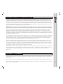
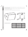
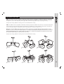
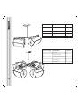
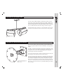
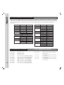
O W N E R ’ S
M A N U A L
CONTENTS
1.0: INTRODUCTION
2.0: UNPACKING
3.0: CONNECTORS/CABLING
4.0: POLARITY CHECKING
5.0: AMPLIFICATION & POWER HANDLING
6.0: CROSSOVERS
7.0: EQUALISATION
8.0: DIMENSIONS
9.0: PERFORMANCE DATA
10.0: TECHNICAL SPECIFICATIONS
11.0: RIGGING & SUSPENSION
11.1
11.2
11.3
11.4
11.5
General Safety Advice
Secur - ET V6Y Yoke bracket
Secur - ET VCB2 & VCB4
Secur - ET VCS Ceiling Saddle
Secur - ET V8B Wall Mounting Bracket
12.0: SYSTEM CONFIGURATION & OEM CONTROLLERS
13.0: V6 RECOMMENDED SERVICE PARTS & ACCESSORIES
14.0: WARRANTY
15.0: DECLARATION OF CONFORMITY
2
1.0: INTRODUCTION
Featuring a high power 150mm (6") Dual Concentric™ drive unit with Tannoy's unique point source technology, the Tannoy V6
provides a compact solution for high quality music and speech reproduction. Installation, in even the smallest of venues, is made
simpler due to the 90 degree conical dispersion of the Dual Concentric™ which allows either vertical or horizontal mounting
without affecting sound quality or compromising performance.
The V6 comprises one 150mm (6") Dual Concentric™ driver in which the low frequency (LF) and high frequency (HF) sources
are coincidentally aligned to a point source, resulting in a smooth uniform frequency response over a wide area. The sophisticated
CAD designed waveguide combines 90 degree conical dispersion and excellent acoustic impedance characteristics.
As a foreground system, installation is made simple with a range of Secur-ET mounting hardware, designed specifically for the
V series. As a versatile low profile stage monitor, the conical coverage pattern gives the performer greater freedom of movement
than allowed by conventional horn loaded designs.
The V6 has been designed for use with the Tannoy TX1 controller, which will equalise the system resulting in improved bass
performance as well as providing a 2-way crossover function, for use with separate sub-bass systems.
2.0: UNPACKING
Every Tannoy V6 product is carefully tested and inspected before being packaged and leaving the factory. After unpacking your
loudspeaker, please inspect for any exterior physical damage, and save the carton and any relevant packaging materials in
case the loudspeaker again requires packing and shipping. In the event that damage has been sustained in transit notify your
dealer immediately.
3.0: CONNECTORS/CABLING
The V6 is fitted with two 4mm binding posts and a 4-pole Neutrik Speakon' for connection to the amplifier. These are paralleled
within the enclosure.
The two binding post terminals are capable of accepting cables with a conductor of up to 6mm.
Red is Positive
Black is Negative
Speakon has the following advantages over EP and XLR type connectors: All terminations are solderless; this makes life easier
at the time of installation or when field servicing is required. Contacts will accept 6 sq. mm wire with an outside diameter of up
to 15mm and a current rating of 30 Amps. The pins of the 2 Speakon sockets identified input/output on the rear of the input
panel are paralleled within the enclosure. Tannoy have adopted the conventional wiring standard for the V6 product:
Pin 1+ is Positive
Pin 1- is Negative
For a worldwide list of Neutrik distributors see http://www.neutrik.com/
3
Cable choice consists mainly of selecting the correct cross sectional area in relation to the cable length and the load impedance.
A small cross sectional area would increase the cables series resistance, inducing power loss and response variations (damping
factor).
Connectors should be wired with a minimum of 2.5 sq. mm (12 gauge) cable. This will be perfectly satisfactory under normal
conditions. In the case of very long cable runs the wire size should exceed this, refer to the following table for guidance:
CABLE RUN (m)
C.S.A. OF EACH
CONDUCTOR (mm)
CABLE RESISTANCE
% POWER LOSS
INTO 8 LOAD
% POWER LOSS
INTO 4 LOAD
10
2.5
4.0
6.0
0.14
0.09
0.06
1.7
1.1
0.73
3.5
2.2
1.5
25
2.5
4.0
6.0
0.35
0.22
0.14
4.3
2.7
1.8
8.6
5.4
3.6
50
2.5
4.0
6.0
0.69
0.43
0.29
8.6
5.4
3.6
17.0
11.0
7.2
100
2.5
4.0
6.0
1.38
0.86
0.58
17.0
11.0
7.2
35.0
22.0
14.0
4.0: POLARITY CHECKING
It is most important to check the polarity of the wiring before the speaker system is flown. A simple method of doing this without
a pulse based polarity checker for LF units is as follows: Connect two wires to the +ve and -ve terminals of a PP3 battery. Apply
the wire which is connected to the +ve terminal of the battery to the speaker cable leg which you believe to be connected to
pin 1+ of the speaker connector and likewise the -ve leg of the battery to pin 1-.
If you have wired it correctly the LF drive unit will move forward, indicating the wiring is correct. All that remains now is to connect
the +ve speaker lead to the +ve terminal on the amplifier and the -ve lead to the -ve terminal on the amplifier. If however the
LF driver moves backwards, the input connections need to be inverted.
4
If problems are encountered, inspect the cable wiring in the first instance. It should also be noted that different amplifier
manufacturers utilise different pin configurations and polarity conventions, if you are using amplifiers from more than one
manufacturer, check the polarity at the amplifiers as well as the loudspeakers.
5.0: AMPLIFICATION & POWER HANDLING
As with all professional loudspeaker systems, the power handling is a function of voice coil thermal capacity. Care should be
taken to avoid running the amplifier into clip (clipping is the end result of overdriving any amplifier). Damage to the loudspeaker
will be sustained if the amplifier is driven into clip for any extended period of time. Headroom of at least 3dB should be allowed.
When evaluating an amplifier, it is important to take into account its behaviour under low impedance load conditions. A
loudspeaker system is highly reactive and with transient signals it can require more current than the nominal impedance would
indicate.
Generally a higher power amplifier running free of distortion will do less damage to the loudspeaker than a lower power amplifier
continually clipping. It is also worth remembering that a high powered amplifier running at less than 90% of output power
generally sounds a lot better than a lower power amplifier running at 100%. An amplifier with insufficient drive capability will
not allow the full performance or the loudspeaker to be realised. (See technical specifications section for recommended amplifier
power)
It is important when using different manufacturers amplifiers in a single installation that the have very closely matched gains,
the variation should be less than +/- 0.5dB. This precaution is important to the overall system balance when only a single active
crossover is being used with multiple cabinets; it is therefore recommended that the same amplifiers be used throughout.
6.0: CROSSOVERS
The V6 is supplied as standard for passive operation via the internal crossover network. If higher peak outputs and additional
low frequency output is required then the V6 can be used in conjunction with the Tannoy TX1 controller/crossover which provides
high pass filtering and a degree of parametric equalisation, as well as a fixed crossover point for use with sub-bass loudspeakers
(See the TX1 user manual for further information). The Tannoy TDX2 Digital controller will also perform the above functions with
additional control and features including limiting and delay (See the relevant literature on the TDX2 for further information).
7.0: EQUALISATION
The V6 loudspeaker is designed to need no equalisation or correction to overcome system limitations. As a result, it will only
need equalisation to compensate for difficult acoustic environments.
Over equalisation can reduce system headroom, and introduce phase distortion resulting in greater problems than cures. If
equalisation is required then it should be applied gently and smoothly. The V6 loudspeaker is a point source, phase coherent
designs and violent equalisation will be detrimental to the overall sound quality.
5
11.0: RIGGING & SUSPENSION
11.1: GENERAL SAFETY ADVICE
The Tannoy SecureET™ hardware covered in this guide has been designed to offer quick, simple, cost effective and secure
solutions for mounting specific Tannoy professional loudspeakers. This hardware has been designed and manufactured with a
high safety load factor for its specific role. To ensure the safest possible use of the hardware covered in this guide, it must be
assembled in strict accordance with the instructions specified. The information in these manuals relating to the assembly and
the safe use of these accessories must be understood and followed. The installation of Tannoy professional loudspeakers using
the dedicated hardware should only ever be carried out by fully qualified installers, in accordance with all the required safety
codes and standards that are applied at the place of installation.
WARNING: As the legal requirements for flying change from country to country, please consult you local safety standards office
before installing any product. We also recommend that you thoroughly check any laws and bylaws prior to commencing work.
Tannoy SecureET™ professional hardware has been designed for use with specific Tannoy V Series loudspeakers, and is not
designed or intended for use with any other Tannoy Professional products, or any other devices. Using Tannoy SecureET™
hardware for any purpose other than that indicated in this guide is considered to be improper use. Such use can be very dangerous
as overloading, modifying, assembling in anyway other than that clearly stated in the manual, or damaging Tannoy SeecureET™
hardware will compromise safety.
The component parts of any Tannoy SecureET™ hardware device must only be assembled using the accessory kits supplied and
in strict compliance with the user manual. The use of other accessories or non-approved methods of assembly may result in an
unsafe hardware system by reducing the load safety factor. Welding, or any other method of permanently fixing hardware
components together or to the integral fixing points in the cabinet should never be used.
Whenever a Tannoy professional loudspeaker is fixed to a surface using a Tannoy SecureET™ hardware device, the installer
must ensure that the surface is capable of safely and securely supporting the load. The hardware employed must be safely,
securely, and in accordance with the manual, attached both to the loudspeaker and also to the surface in question, using only
the fixing holes provided as standard and covered in the manual. Secure fixings to the building structure are vital. Seek help
from architects, structural engineers or other specialists if in any doubt.
All loudspeakers flown in theatres, nightclubs, conference centre or other places of work and entertainment must, be provided
with an independent, correctly rated and securely attached secondary safety - in addition to the principle hardware device. This
secondary safety must prevent the loudspeaker from dropping more than 150mm (6") should the principle hardware
device fail.
11.2: SECUR ET™ - V6Y YOKE BRACKET
The V6Y is a discreet yoke style bracket, available in both black and white, and is used to mount the Tannoy V6 in both portrait
and landscape orientations. The Tannoy V6 loudspeaker is fixed to the bracket using the M6 bolts and washers supplied in the
accessory pack
Only the screws, fasteners, shakeproof and plain washers specified on figure 3. should be used to assemble the VMY bracket.
The arms of the V6Y have long slots, through which M6 bolts are fitted, and screwed into the integral M6 inserts in the top and
bottom of the Tannoy V6 cabinet.
9
The arms of the V6Y have long slots, through which M6 bolts are fitted, and screwed into the integral M6 inserts in the top and
bottom of the Tannoy V6 cabinet.
These slots allow the installer to easily and precisely adjust the distance between the loudspeaker and the mounting surface for
optimal discreet installation of the Tannoy V6.
Use the 20mm hole to pass the loudspeaker cable through before fixing the bracket to the wall.
Use the table of parts along with the
assembly drawing to assemble the V6Y.
10
ASSEMBLY VIEW
DESCRIPTION
QUANTITY
1
Yoke Bracket
1
2
Washer M6 Plain
2
3
Washer M6 Spring
2
4
M6 x 25 Button Head Screw
2
5
Rubber Friction Washer
2
11.3: SECUR ET: VCB2 & VCB4
VCB2: The VCB2 cluster bar is available in both black and white finishes and provides a platform onto which 2 x Tannoy V6
loudspeakers can be mounted using the V6Y yoke bracket (not supplied in the VCB2 kit). A number of different loudspeaker
arrangements can be made depending on the application and the coverage pattern required (see figures 1 & 2).
Using the VCS ceiling saddle the resulting cluster can be attached to the ceiling.
VCB4: The VCB4 cluster bar (available in both black and white) provides the platform onto which 3-4 x Tannoy V6 loudspeakers
can be mounted using the V6Y yoke bracket (not supplied in the VCB4 kit). A number of different loudspeaker arrangements
can be made depending on the application and the coverage pattern required (see figures 3-6).
N.B. When using the VCB4 cluster bar system, one of the cluster bars is mounted above the other to produce a cross
formation. To ensure an equal mounting height, the 2 x Tannoy V6 loudspeakers being flown from the lower cluster bar
should be attached to the upper surface of this bar. While the 2 x Tannoy V6 loudspeakers being flown from the upper
bar should be attached to the underside of this cluster bar.
Using the VCS ceiling saddle the resulting cluster can be attached to the ceiling.
Fig. 1.
Fig. 2.
Fig. 3.
Fig. 4.
Fig. 5.
Fig. 6.
11
12
Contents of VCB2
DESCRIPTION
QUANTITY
1
Cluster Bar
1
2
Washer M10 Plain
2
3
Screw M10x40 Button Head
2
4
M10 Nyloc Nut
2
5
Blanking Plug
2
Contents of VCB4
DESCRIPTION
QUANTITY
1
Cluster Bar
1
2
Washer M10 Plain
2
3
Screw M10x40 Button Head
2
4
M10 Nyloc Nut
2
5
Blanking Plug
2
11.4: SECUR - ET™ VCS CEILING SADDLE
The VCS ceiling saddle available in both black and white finishes,
and is to be used in conjunction with the V6Y, VCB2, VCB4 and a
length of M10 threaded rod (not supplied by Tannoy Limited). The
VCS ceiling saddle allows the Tannoy V6 loudspeaker to be suspended
at a user defined distance from the ceiling as shown in Figure 1.
Included with the VCS is an M10 nut. This should be used to secure
and lock the threaded rod in place at the top of the ceiling saddle.
Fig. 1.
11.5: SECUR - ET™ V8B WALL MOUNTING BRACKET
The V6 can be wall or ceiling mounted by using the V8B bracket
which is designed to offer the maximum flexibility in selecting desired
angles.
The V8B is supplied with M6 bolts for fixing to the loudspeaker, hinge
clips which can be used to alter the angle of the wall fixing plate and
an allen key to secure the arm length adjustment as well as the
desired angle of 'tilt' of the loudspeaker .
The hinged wall mount plate enables the V8B to be fixed to flat walls
and ceilings or to fit onto internal or external corners.
The Tannoy V6 loudspeaker is also
compatible with Omnimount™ 75
Series Hardware
When the desired angle of tilt has been decided for the loudspeaker,
the allen bolt holding the loudspeaker mounting plate onto the arm
of the V8B can be tightened, the sprockets will hold the assembly
firm ensuring it will not slip. The arm length can also be adjusted if
desired. It is imperative that the bracket is fixed soundly to the wall.
Be sure to use the correct fixings (e.g. Rawbolt, Rawplug) according
to the wall type.
13
12.0: SYSTEM CONFIGURATIONS & OEM CONTROLLERS
With the vast array of digital loudspeaker management systems available it is inevitable that the user may opt to use a controller
other than the TX1 & TDX2 as part of a large scale integrated system. The V6 has been designed to need no external equalisation
to overcome system limitations. If the V6 is to be used alone with additional bass enhancement required and have the frequency
response limits tighter than +/- 3dB as stated in section 10, then apply the parameters in the table below for optimised
performance:
PARAMETER
UNIT/NAME
Gain
Delay
Polarity
(dB)
(ms)
User definable
User definable
Positive
HPF
Freq (Hz)
Slope (dB/oct)
Filter Shape
49.6
24
Butterworth
Freq (Hz)
Slope (dB/oct)
Filter Shape
Thru
NA
NA
Freq (Hz)
Level (dB)
Type
Q / Bandwidth
303
+1.0
Parametric
2 / 0.5
LPF
PEQ 1
14
PARAMETER
UNIT/NAME
PEQ 2
Freq (Hz)
Level (dB)
Type
Q / Bandwidth
857
-0.8
Parametric
2.5 / 0.4
PEQ 3
Freq (Hz)
Level (dB)
Type
Q / Bandwidth
1500
+1.5
Parametric
1.7 / 0.6
PEQ 4
Freq (Hz)
Level (dB)
Type
Q / Bandwidth
8810
+2.5
Parametric
1.9 / 0.53
PEQ 5
(not used)
Freq (Hz)
Level (dB)
Type
Q / Bandwidth
13.0: V6 SERVICE PARTS & ACCESSORIES
13.0: V6 SERVICE PARTS & ACCESSORIES
PART NUMBER
DESCRIPTION
PART NUMBER
DESCRIPTION
7900 0742
7900 0683
7300 0927
Driver Kit - 1728
HF Diaphragm Kit
Crossover - 1456
8000 0740
Tannoy TX1 Active system controller/
2-way crossover
8001 1930
8001 3310
8001 3311
8001 2740
8001 2750
8001 2760
8001 2770
8001 2830
8001 2840
V6Y - Secure ET- V6 Yoke Bracket (Black)
V6Y - Secure ET- V6 Yoke Bracket (White)
VCB2 - Secure ET - Cluster Bar (Black)
VCB2 - Secure ET - Cluster Bar (White)
VCB4 - Secure ET - Cluster Bar (Black)
VCB4 - Secure ET - Cluster Bar (Black)
VCS - Secur ET - Ceiling Saddle (Black)
VCS - Secur ET - Ceiling Saddle (White)
Tannoy TDX2 Digital System Controller
90 - 250V UK
Tannoy TDX2 Digital System Controller
90 - 250V EUR
Tannoy TDX2 Digital System Controller
90 - 250V USA
8001 1940
8001 1950
14.0: WARRANTY
NO MAINTENANCE OF THE V6 LOUDSPEAKERS IS NECESSARY.
All Tannoy professional loudspeaker products are covered by a 5 year warranty from the date of manufacture subject to the
absence of misuse, overload or accidental damage. Claims will not be considered is the serial number has been altered or
removed. Work under warranty should only be carried out by a Tannoy dealer or service agent. This warranty in no way affects
your statutory rights. For further information please contact your dealer or distributor in your country. If you cannot locate your
distributor please contact Customer Services, Tannoy Ltd at the address given below.
Customer Services, Tannoy Ltd., Rosehall Industrial Estate, Coatbridge, Strathclyde, ML5 4TF, Scotland
Telephone: 01236 420199 (National) +44 1236 420199 (International)
Fax: 01236 428230 (National) +44 1236 428230 (International)
E-Mail: [email protected]
DO NOT SHIP ANY PRODUCT TO TANNOY WITHOUT PREVIOUS AUTHORISATION
Our policy commits us to incorporating improvements to our products through continuous research and development. Please
confirm current specifications for critical applications with your supplier.
15.0: DECLARATION OF CONFORMITY
The following apparatus is/are manufactured in the United Kingdom by Tannoy Ltd of Rosehall Industrial estate,
Coatbridge, Scotland, ML5 4TF and conform(s) to the protection requirements of the European Electromagnetic
Compatibility Standards and Directives relevant to Domestic Electrical Equipment. The apparatus is designed and
constructed such that electromagnetic disturbances generated do not exceed levels allowing radio and
telecommunications equipment and other apparatus to operate as intended, and, the apparatus has an adequate
level of intrinsic immunity to electromagnetic disturbance to enable operation as specified and intended.
Details of the Apparatus:
Model Number:
Associated Technical File:
Applicable Standards:
Electrical Safety:
Tannoy Contractor Loudspeaker
V6
EMCV6
EN 50081-1 Emission
EN 50082-1 Immunity
EN 60065
Signed:
Position:
Date:
For Tannoy Ltd
Engineering Director - Tannoy Professional Products
10/06/2002
15
T: +44 (0) 1236 420199
F: +44 (0) 1236 428230
E: [email protected]
Tannoy North America
T: (519) 745 1158
F: (519) 745 2364
E: [email protected]
Tannoy adopts a policy of continuous improvement and product specification is subject to change.
6481 0409
Tannoy United Kingdom