1
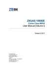
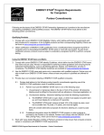
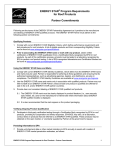
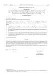
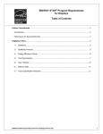
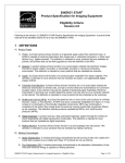
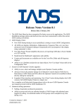
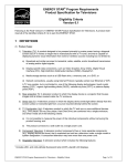
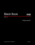
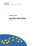
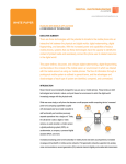
ENERGY STAR® Program Requirements for Small Network Equipment Partner Commitments Following are the terms of the ENERGY STAR Partnership Agreement as it pertains to the manufacture and labeling of ENERGY STAR certified products. The ENERGY STAR Partner must adhere to the following partner commitments: Certifying Products 1. Comply with current ENERGY STAR Eligibility Criteria, which define performance requirements and test procedures for Small Network Equipment. A list of eligible products and their corresponding Eligibility Criteria can be found at www.energystar.gov/specifications. 2. Prior to associating the ENERGY STAR name or mark with any product, obtain written ENERGY STAR certification from a Certification Body recognized by EPA for Small Network Equipment. As part of this certification process, products must be tested in a laboratory recognized by EPA to perform Small Network Equipment testing. A list of EPA-recognized laboratories and certification bodies can be found at www.energystar.gov/testingandverification. 3. Ensure that all of Partner’s products that bear the ENERGY STAR certification mark meet the following standard: x Product material requirements as defined in restriction of hazardous substances (RoHS) regulations, as generally accepted. This includes exemptions in force at the date of product manufacture: where the maximum concentration values tolerated by weight in homogeneous materials are: lead (0.1%), mercury (0.1%), cadmium (0.01%), hexavalent chromium (0.1%), polybrominated biphenyls (PBB) (0.1%), or polybrominated diphenyl ethers (PBDE) (0.1%). Batteries are exempt. Notes: x The explicit intention is to harmonize with EU RoHS. x For purposes of ENERGY STAR third-party certification, these requirements shall not be reviewed when products are initially certified nor during subsequent verification testing. Rather, EPA reserves the right to request supporting documentation at any time. Using the ENERGY STAR Name and Marks 4. Comply with current ENERGY STAR Identity Guidelines, which define how the ENERGY STAR name and marks may be used. Partner is responsible for adhering to these guidelines and ensuring that its authorized representatives, such as advertising agencies, dealers, and distributors, are also in compliance. The ENERGY STAR Identity Guidelines are available at www.energystar.gov/logouse. 5. Use the ENERGY STAR name and marks only in association with certified products. Partner may not refer to itself as an ENERGY STAR Partner unless at least one product is certified and offered for sale in the U.S and/or ENERGY STAR partner countries. 6. Provide clear and consistent labeling of ENERGY STAR certified Small Network Equipment. 6.1. Partner must use the ENERGY STAR mark in all of the following ways: 6.1.1. On the top or front of the product. Labeling on the top or front of the product may be permanent or temporary. All temporary labeling must be affixed to the top or front of the product with an adhesive or cling-type application; ENERGY STAR Program Requirements for Small Network Equipment – Partner Commitments 1 6.1.2. In product literature (i.e. user manuals, spec sheets, etc.); 6.1.3. On product packaging for products sold at retail; and 6.1.4. On the Partner’s Internet site where information about ENERGY STAR certified models is displayed: 6.2. If additional information about the ENERGY STAR program(s) or other products provided by the Partner on its Web site, Partner must comply with the ENERGY STAR Web Linking Policy, which can be found at www.energystar.gov/partners. Verifying Ongoing Product Certification 7. Participate in third-party verification testing through a Certification Body recognized by EPA for Small Network Equipment, providing full cooperation and timely responses, EPA/DOE may also, at its discretion, conduct tests on products that are referred to as ENERGY STAR certified. These products may be obtained on the open market, or voluntarily supplied by Partner at the government’s request. Providing Information to EPA 8. Provide unit shipment data or other market indicators to EPA annually to assist with creation of ENERGY STAR market penetration estimates, as follows: 8.1. Partner must submit the total number of ENERGY STAR certified Small Network Equipment shipped in the calendar year or an equivalent measurement as agreed to in advance by EPA and Partner. Partner shall exclude shipments to organizations that rebrand and resell the shipments (unaffiliated private labelers). 8.2. Partner must provide unit shipment data segmented by meaningful product characteristics (e.g., type, capacity, presence of additional functions) as prescribed by EPA. 8.3. Partner must submit unit shipment data for each calendar year to EPA or an EPA-authorized third party, preferably in electronic format, no later than March 1 of the following year. Submitted unit shipment data will be used by EPA only for program evaluation purposes and will be closely controlled. If requested under the Freedom of Information Act (FOIA), EPA will argue that the data is exempt. Any information used will be masked by EPA so as to protect the confidentiality of the Partner; 9. Report to EPA any attempts by recognized laboratories or Certification Bodies (CBs) to influence testing or certification results or to engage in discriminatory practices. 10. Notify EPA of a change in the designated responsible party or contacts within 30 days using the My ENERGY STAR Account tool (MESA) available at www.energystar.gov/mesa. Performance for Special Distinction In order to receive additional recognition and/or support from EPA for its efforts within the Partnership, the ENERGY STAR Partner may consider the following voluntary measures, and should keep EPA informed on the progress of these efforts: Provide quarterly, written updates to EPA as to the efforts undertaken by Partner to increase availability of ENERGY STAR certified products, and to promote awareness of ENERGY STAR and its message. Consider energy efficiency improvements in company facilities and pursue benchmarking buildings through the ENERGY STAR Buildings program. ENERGY STAR Program Requirements for Small Network Equipment – Partner Commitments 2 Purchase ENERGY STAR certified products. Revise the company purchasing or procurement specifications to include ENERGY STAR. Provide procurement officials’ contact information to EPA for periodic updates and coordination. Circulate general ENERGY STAR certified product information to employees for use when purchasing products for their homes. Feature the ENERGY STAR mark(s) on Partner website and other promotional materials. If information concerning ENERGY STAR is provided on the Partner website as specified by the ENERGY STAR Web Linking Policy (available in the Partner Resources section of the ENERGY STAR website), EPA may provide links where appropriate to the Partner website. Ensure the power management feature is enabled on all ENERGY STAR certified displays and computers in use in company facilities, particularly upon installation and after service is performed. Provide general information about the ENERGY STAR program to employees whose jobs are relevant to the development, marketing, sales, and service of current ENERGY STAR certified products. Provide a simple plan to EPA outlining specific measures Partner plans to undertake beyond the program requirements listed above. By doing so, EPA may be able to coordinate, and communicate Partner’s activities, provide an EPA representative, or include news about the event in the ENERGY STAR newsletter, on the ENERGY STAR website, etc. The plan may be as simple as providing a list of planned activities or milestones of which Partner would like EPA to be aware. For example, activities may include: (1) increasing the availability of ENERGY STAR certified products by converting the entire product line within two years to meet ENERGY STAR guidelines; (2) demonstrating the economic and environmental benefits of energy efficiency through special in-store displays twice a year; (3) providing information to users (via the website and user’s manual) about energy-saving features and operating characteristics of ENERGY STAR certified products; and (4) building awareness of the ENERGY STAR Partnership and brand identity by collaborating with EPA on one print advertorial and one live press event. Join EPA's SmartWay Transport Partnership to improve the environmental performance of the company's shipping operations. The SmartWay Transport Partnership works with freight carriers, shippers, and other stakeholders in the goods movement industry to reduce fuel consumption, greenhouse gases, and air pollution. For more information on SmartWay, visit www.epa.gov/smartway. Join EPA’s Green Power Partnership. EPA's Green Power Partnership encourages organizations to buy green power as a way to reduce the environmental impacts associated with traditional fossil fuelbased electricity use. The partnership includes a diverse set of organizations including Fortune 500 companies, small and medium businesses, government institutions as well as a growing number of colleges and universities. For more information on Green Power, visit www.epa.gov/greenpower. ENERGY STAR Program Requirements for Small Network Equipment – Partner Commitments 3 ENERGY STAR® Product Specification for Small Network Equipment Eligibility Criteria Version 1.0 Following is the ENERGY STAR product specification for Small Network Equipment. A product shall meet all of the identified criteria if it is to earn the ENERGY STAR. 1 DEFINITIONS A) Product Classifications: 1) Network Equipment: A device whose primary function is to pass Internet Protocol (IP) traffic among various network interfaces / ports. 2) Small Network Equipment (SNE): Network Equipment that is intended to serve users in either small networks or a subset of a large network. SNE includes a) all Network Equipment with integral wireless capability and b) other Network Equipment meeting all of the following criteria: a) Designed for stationary operation; b) Contains no more than eleven (11) wired Physical Network Ports; c) Primary configuration for operation outside of standard equipment racks; d) Meets the definition of one or more of the Product Types defined below. 3) Large Network Equipment: Network Equipment that is rack-mounted, intended for use in standard equipment racks, and/or contains more than eleven (11) ports for wired network. B) Small Network Equipment Types: 1) Broadband Access Equipment a) Broadband Modem: A device that transmits and receives digitally-modulated analog signals over a wired or optical network as its primary function. The Broadband Modem category does not include devices with integrated Router, Switch, or Access Point functionality. b) Integrated Access Device (IAD): A network device with a modem and one or more of the following functions: wired network routing, multi-port Ethernet switching and/or access point functionality. c) Optical Network Termination Device (ONT): A type of device that converts signals between copper (wired) or wireless connections and an optical fiber connection. ONTs are available in either desktop or building-mounted versions with different connectivity options. 2) Local Network Equipment a) Access Point: A device that provides wireless network connectivity to multiple clients as its primary function. For the purposes of this specification, Access Points include devices providing only IEEE 802.11 (Wi-Fi) connectivity. b) Router: A network device that determines the optimal path along which network traffic should be forwarded as its primary function. Routers forward packets from one network to another based on network layer information. Devices fitting this definition may provide ENERGY STAR Program Requirements for Small Network Equipment – Eligibility Criteria Page 1 of 8 both Router functionality and wireless network capability. c) Switch: A network device that filters, forwards, and floods frames based on the destination address of each frame as its primary function. The switch operates at the data link layer of the OSI model. Does the device provide Modem functionality? Yes No Broadband Access Equipment Broadband Modem ONT IAD Local Network Equipment Access Point Router Switch (Cable, DSL) Figure 1: Product Type Assignment C) Operational Modes and States: 1) On Mode: The product is connected to a power source, is ready to use, and is providing one or more primary functions. a) Idle State: The product is in On Mode and the data rate is 0 kb/s. b) Low Data Rate: The product is in On Mode and traffic is passed across ports at 1.0 kb/s (0.5 kb/s in each direction) as defined in the test procedure. c) High Data Rate: The product is in On Mode and traffic is passed across ports at a selected reference rate as defined in the test procedure. D) Components: 1) External Power Supply (EPS): A component contained in a separate physical enclosure from the SNE product designed to convert line voltage ac input into lower voltage ac or dc output(s) for the purpose of powering the SNE product. An EPS must connect to the SNE product via a removable or hard-wired male/female electrical connection, cable, cord or other wiring. E) Marketing or Shipment Terminology: 1) Cable, Satellite, and Telecom Service Provider (“Service Provider”): An entity that provides Internet connectivity to subscribers with whom it has an ongoing contractual relationship. 2) Manufacturing Partner: An entity that manufactures, or markets OEM-manufactured SNE for sale to either end customers or Service Providers. F) Additional Terms: 1) End Point Device: A device that functions as either an originator or destination for network traffic passed through Network Equipment. Examples of end point devices include computers, servers, set-top boxes, IP-capable televisions, IP phones, etc. For the purposes ENERGY STAR Program Requirements for Small Network Equipment – Eligibility Criteria Page 2 of 8 of this specification, an end point device is not considered network equipment. 2) Energy Efficient Ethernet (EEE): A technology which enables reduced power consumption of Ethernet interfaces during times of low data throughput. Specified by IEEE 802.3az. 3) Link Rate: The maximum PHY bit rate possible on a particular link (e.g., 1000BASE-T Ethernet supports 1 Gb/s in each direction [2 Gb/s total]; IEEE 802.11g supports 54 Mb/s total). 4) Physical Data Port: An integrated physical connection point primarily intended to accept nonIP data. For the purposes of this specification, a port must support one of the following media types to fit this definition: a) Universal Serial Bus (USB); b) Firewire; c) Thunderbolt; d) SATA; e) SCSI; or f) RS-232. 5) Physical Network Port: An integrated physical connection point primarily intended to accept IP or similar traffic via a cable. For the purposes of this specification, a port must support one of the following media types to fit this definition: a) Twisted Pair Copper (Ethernet, DSL); b) Coaxial Cable (DOCSIS); or c) Fiber Optic. 6) Power over Ethernet (PoE): A technology which enables transfer of electrical power, along with data, to network end point devices through an Ethernet cable. Currently specified by IEEE 802.3af and IEEE 802.3at. 7) Standard Equipment Rack: An equipment enclosure commonly seen in data centers or managed facilities and intended to house a variety of information technology equipment. Front panel width is typically 19 inches (482.6 mm) in width. Standard Equipment Racks are defined by EIA-310, IEC 60297, or DIN 41494. 8) Unit Under Test (UUT): The network equipment device being tested. 9) Wireless Local Area Network (WLAN) Test Client: A device that is capable of establishing an 802.11x link with an Access Point (AP) and transmitting data to and receiving from the AP. 10) Full Network Connectivity: The ability of an End Point Device to maintain network presence while in Sleep Mode or another low power mode (LPM) of equal or lower power consumption and intelligently wake when further processing is required (including occasional processing required to maintain network presence). Presence of the End Point Device, its network services and applications is maintained even though the End Point Device is in a LPM. From the vantage point of the network, an End Point Device with full network connectivity that is in LPM is functionally equivalent to an idle End Point Device with respect to common applications and usage models. Full network connectivity in LPM is not limited to a specific set of protocols but can cover applications installed after initial installation. Also referred to as “network proxy” functionality and as described in the Ecma-393 standard. a) Network Proxy - Base Capability: To maintain addresses and presence on the network while in LPM, the system handles IPv4 ARP and IPv6 NS/ND. b) Network Proxy - Full Capability: While in LPM, the system supports Base Capability, Remote Wake, and Service Discovery/Name Services. ENERGY STAR Program Requirements for Small Network Equipment – Eligibility Criteria Page 3 of 8 c) Network Proxy - Remote Wake: While in LPM, the system is capable of remotely waking upon request from outside the local network. Includes Base Capability. d) Network Proxy - Service Discovery/Name Services: While in LPM, the system allows for advertising host services and network name. Includes Base Capability. 11) External Proxy Capability: The ability of an SNE device to maintain Full Network Connectivity on behalf of an End Point Device. Must include an implementation of a standard protocol for communicating between the End Point Device and the SNE device. Note: A known such protocol is mDNS. Waking the sleeping End Point Device is typically accomplished by WakeOn-LAN, a wireless equivalent, or some other directed traffic. G) Product Family: A group of product models that are (1) made by the same manufacturer, (2) subject to the same ENERGY STAR certification criteria, and (3) of a common basic design. Product models within a family differ from each other according to one or more characteristics or features that either (1) have no impact on product performance with regard to ENERGY STAR certification criteria, or (2) are specified herein as acceptable variations within a product family. For SNE, acceptable variations within a product family include: 1) Color, 2) Housing, or 3) Any of the functional adders specified in Table 2. 2 SCOPE 2.1 2.1.1 2.2 Included Products Products that meet the definition for Small Network Equipment as specified herein are eligible for ENERGY STAR certification, with the exception of products listed in Section 2.2. In addition, SNE shall meet one of the following equipment type definitions: i. Broadband Modems (Cable, DSL); ii. Optical Network Termination Device (ONT); iii. Integrated Access Device (IAD); iv. Router; v. Switch; or vi. Access Point. Excluded Products 2.2.1 Products that are covered under other ENERGY STAR product specifications are not eligible for certification under this specification. The list of specifications currently in effect can be found at www.energystar.gov/specifications. 2.2.2 The following products are not eligible for certification under this specification: i. Network Equipment capable of accepting interchangeable modules, such as line cards or additional power supplies; ii. Network Equipment with one or more network ports using pluggable or modular media adapters such as Gigabit Interface Convertor (GBIC) or Small Form-factor Pluggable (SFP) modules. This does not include USB ports;; iii. Network Equipment whose primary wireless capability is not IEEE 802.11 (Wi-Fi); ENERGY STAR Program Requirements for Small Network Equipment – Eligibility Criteria Page 4 of 8 iv. Network Equipment that receive direct dc power (PoE, USB) or provide power through PoE; v. Large Network Equipment; and vi. Network Equipment that is marketed and sold as enterprise Network Equipment and can be controlled and configured for operation by an external controller. 3 CERTIFICATION CRITERIA 3.1 Significant Digits and Rounding 3.1.1 All calculations shall be carried out with directly measured (unrounded) values. 3.1.2 Unless otherwise specified, compliance with specification limits shall be evaluated using directly measured or calculated values without any benefit from rounding. 3.1.3 Directly measured or calculated values that are submitted for reporting on the ENERGY STAR website shall be rounded to the nearest significant digit as expressed in the corresponding specification limit. 3.2 Power Supply Requirements 3.2.1 External Power Supplies (EPSs): EPSs (single- and multiple-voltage) shall meet the level V performance requirements under the International Efficiency Marking Protocol and include the level V marking. Additional information on the Marking Protocol is available at http://www.plugloadsolutions.com/docs/collatrl/print/Generalized_Internal_Power_Supply_Effici ency_Test_Protocol_R6.6.pdf. i. 3.3 External Power Supplies shall meet level V requirements when tested using the Test Method for Calculating the Energy Efficiency of Single-Voltage External Ac-Dc and Ac-Ac Power Supplies, Aug. 11, 2004. Efficiency Criteria 3.3.1 Average Power (PAVG): Calculated Average Power (PAVG) per Equation 1 shall be less than or equal to the maximum requirement for Average Power (PAVG_MAX), as calculated per Equation 2. Equation 1: Average Power Calculation (PAVG) for Small Network Equipment PAVG = Averageൣܲௐே̴்ாௌ் ǡ ܲே̴்ாௌ் ǡ ܲௐூோாாௌௌ̴்ாௌ் ൧ Where: Average[xi] = Average of terms (xi) applicable to the UUT; PWAN_TEST = Measured power in Wired Network – WAN test, at 1.0 kb/s (W); PLAN_TEST = Measured power in Wired Network – LAN test, half of available wired LAN ports populated, at 1.0 kb/s (W); PWIRELESS_TEST = Measured power in Wireless Network – WLAN test, at 1.0 kb/s (W). Equation 2: Maximum Average Power (PAVG_MAX) Calculation for Small Network Equipment PAVG_MAX = PBASE + σୀଵ ܲ Where: PBASE = Base power allowance (W) from Table 1; PADDi =The power allowance as specified in Table 2 for each feature present in the device, for a total of n such allowances. ENERGY STAR Program Requirements for Small Network Equipment – Eligibility Criteria Page 5 of 8 Table 1: Base Power Allowances Broadband Modem – Cable P_BASE (watts) Version 1.0 5.7 Broadband Modem – ADSL 4.0 ONT 4.4 IAD - Cable 6.1 IAD - ADSL 5.5 IAD - VDSL 7.5 Router 3.1 Switch 0.6 Access Point 2.0 Product Type Table 2: Additional Functional Adders Feature Power Allowance (PADD) in watts Fast Ethernet (100Base-T) 0.1 Gigabit Ethernet (1000Base-T) 0.3 Wi-Fi (802.11a/b/g/n) 0.7 802.11n per Receive Spatial Stream 0.2 802.11ac per Receive Spatial Stream 1.3 Plain Old Telephone Service (RJ11/RJ14) 0.5 Notes Allowance applied once per port present in the UUT. Allowance applied once per port present in the UUT. Allowance applied once for the UUT for availability of Wi-Fi connectivity. Allowance applied to total number of 2.4 GHz and 5.0 GHz 802.11n receive spatial streams. Only applicable for products that ship with simultaneous dual band Wi-Fi enabled. Allowance applied to 5.0 GHz 802.11ac receive spatial streams only. Only applicable for products that ship with simultaneous dual band Wi-Fi enabled. Allowance applied once per port, up to a maximum of two ports. 3.3.2 Energy Efficiency Ethernet (EEE) Incentive: SNE products that ship with IEEE 802.3az compliant Gigabit Ethernet ports may claim a 0.2 watt additional adder for each Gigabit port when calculating PADD. 3.3.3 External Proxy Incentive: SNE products that ship with External Proxy Capability may claim one of the following adders in Table 3 when calculating PADD based on the level of Proxy functionality in the product, as defined in Section 1.F.10. ENERGY STAR Program Requirements for Small Network Equipment – Eligibility Criteria Page 6 of 8 Table 3: External Proxy Incentives Capability Incentive Value in watts Base Capability 0.2 Remote Wake 0.5 Service Discovery/ Name Services 0.8 Full Capability 1.0 4 TESTING 4.1 4.1.1 Test Methods When testing SNE, the test methods identified in Table 4 shall be used to determine certification for ENERGY STAR. Table 4: Test Methods for ENERGY STAR Certification Product Type Test Method All ENERGY STAR Test Method for Small Network Equipment, Rev. Aug-2013 4.1.2 Products that have both ADSL and VDSL functionality shall be tested using their VDSL functionality. 4.1.3 Products that have the DOCSIS 3.0 energy management 1x1 capability shall be tested in an environment that allows this feature to operate at low data traffic rates. 4.2 4.2.1 4.2.2 4.3 4.3.1 Number of Units Required for Testing Representative Models shall be selected for testing per the following requirements: i. For certification of an individual product model, a product configuration equivalent to that which is intended to be marketed and labeled as ENERGY STAR is considered the Representative Model; ii. For certification of a product family, the configuration that consumes the most energy within the family shall be considered the Representative Model. If models in a product family span multiple categories, product configurations that represent the worst-case power consumption for each product category within the family are considered Representative Models. When submitting product families, manufacturers continue to be held accountable for any efficiency claims made about their products, including those not tested or for which data was not reported. A single unit of each Representative Model shall be selected for testing. International Market Certification Products shall be tested for certification at the relevant input voltage/frequency combination for each market in which they will be sold and promoted as ENERGY STAR. ENERGY STAR Program Requirements for Small Network Equipment – Eligibility Criteria Page 7 of 8 4.4 4.4.1 Optional Performance Reporting At the Partner’s option, data on the following performance considerations may be reported along with product evaluation data: i. Ethernet Throughput – The maximum data rate supported by the UUT for which there is no packet loss. ii. Maximum Number of Wireless Clients - The maximum number of clients supported by the UUT. iii. Maximum Number of NAT Clients iv. Maximum number of EEE Gigabit Ethernet ports – The maximum number of IEEE 802.3az compliant Gigabit Ethernet ports supported by the UUT. This reporting requirement shall be mandatory for any products that claim the EEE Incentive in Section 3.3.2. v. Maximum External Proxy Capability – The highest level of External Proxy Capability provided by the UUT as listed in Table 3. This reporting requirement shall be mandatory for any products that claim the External Proxy Incentive in Section 3.3.3. 5 USER INTERFACE 5.1.1 Manufacturers are encouraged to design products in accordance with the user interface standard IEEE P1621: Standard for User Interface Elements in Power Control of Electronic Devices Employed in Office/Consumer Environments. For details, see http://eetd.LBL.gov/Controls. 6 EFFECTIVE DATE 6.1.1 Effective Date: This ENERGY STAR Product Specification for Small Network Equipment shall take effect on September 3, 2013. To certify for ENERGY STAR, a product model shall meet the ENERGY STAR specification in effect on its date of manufacture. The date of manufacture is specific to each unit and is the date on which a unit is considered to be completely assembled. 6.1.2 Future Specification Revisions: EPA reserves the right to change this specification should technological and/or market changes affect its usefulness to consumers, industry, or the environment. In keeping with current policy, revisions to the specification are arrived at through stakeholder discussions. In the event of a specification revision, please note that the ENERGY STAR certification is not automatically granted for the life of a product model. 7 CONSIDERATIONS FOR FUTURE REVISIONS 7.1 Product Scope: EPA will investigate expanding the scope to include enterprise access points that are not covered in Version 1.0. 7.2 Energy Efficiency Criteria: Energy Efficient Ethernet: EPA expects to require that all ports for PHYs addressed by IEEE 802.3az shall be compliant with IEEE 802.3az under the next Version 2.0. 7.3 Network Proxy: EPA will continue to monitor the implementation of proxying capability in SNE hardware and consider the development of a test method to determine the functionality of a network proxy (e.g. one compliant with ECMA-393 ProxZzzy for Sleeping Hosts). ENERGY STAR Program Requirements for Small Network Equipment – Eligibility Criteria Page 8 of 8 ENERGY STAR® Test Method for Small Network Equipment Final Rev. August-2013 1 OVERVIEW The following protocol shall be followed when testing products for compliance with the Version 1.0 ENERGY STAR Small Network Equipment (SNE) specification. 2 APPLICABILITY ENERGY STAR test requirements are dependent upon the feature set of the product under evaluation. The following guidelines shall be used to determine the applicability of each section of this document: x Section 7.2.A) shall be conducted for all SNE products. x Sections 7.2.B), C), and D) shall be completed for applicable product types as referenced in Table 1. Table 1: Test Procedure Structure Test Procedure Section 7.2.B) 7.2.C) 7.2.D) All Devices – Idle State Wired Network – WAN Wired Network – LAN Wireless Network – LAN Modem (DSL, Cable) X X Optical Network Termination Device (ONT) X X Integrated Access Device X X X X Switch/Router X X Routers with Wireless Access Point X Product Type 7.2.A) X 3 DEFINITIONS Unless otherwise specified, all terms used in this document are consistent with the definitions contained in the ENERGY STAR Eligibility Requirements for Small Network Equipment. Acronyms referenced in this ENERGY STAR Test Method draft: x ANSI: American National Standards Institute ENERGY STAR Program Requirements for Small Network Equipment – Test Method (Rev. Aug-2013) Page 1 of 15 x AP: Access Point x dB: Decibels x DHCP: Dynamic Host Configuration Protocol x DSL: Digital Subscriber Line x EIA: Electronic Industries Alliance x EPS: External Power Supply x HPNA: Home Phoneline Networking Alliance x IAD: Integrated Access Device x IEC: International Electrotechnical Commission x IEEE: Institute of Electrical and Electronics Engineers x IMIX: Internet Traffic Mix x IPsec: Internet Protocol Security x ISP: Internet Service Provider x L2TP: Layer 2 Tunneling Protocol x LAN: Local Area Network x LLDP: Link Layer Discovery Protocol x MAC: Media Access Control x MIMO: Multiple-Input/Multiple-Output x MoCA: Multimedia over Coax Alliance x MTU: Maximum Transmission Unit x NAT: Network Address Translation x ONT: Optical Network Terminal x PoE: Power over Ethernet x PON: Passive Optical Network x POTS: Plain Old Telephone Service x PPPoX: Point-to-Point Protocol over X x RF: Radio Frequency x SSID: Service Set Identifier x TIA: Telecommunications Industry Association x TTL: Time To Live x UDP: User Datagram Protocol x USB: Universal Serial Bus x UUT: Unit Under Test x VoIP: Voice over Internet Protocol x VPN: Virtual Private Network ENERGY STAR Program Requirements for Small Network Equipment – Test Method (Rev. Aug-2013) Page 2 of 15 x WAN: Wide Area Network x WLAN: Wireless Local Area Network 4 TEST SETUP A) Test Setup and Instrumentation: Test setup and instrumentation for all portions of this procedure shall be in accordance with the requirements of IEC 62301, Ed. 2.0, “Household electrical appliances – Measurement of standby power”, Section 4, “General Conditions for Measurements”. In the event of conflicting requirements, the ENERGY STAR test method shall take precedence. B) Input Power: Input power shall be as specified in Table 2. Table 2: Input Power Requirements Voltage Voltage Tolerance Maximum Total Harmonic Distortion Frequency Frequency Tolerance North America, Taiwan 115 Vac +/- 1.0 % 2.0 % 60 Hz +/- 1.0 % Europe, Australia, New Zealand 230 Vac +/- 1.0 % 2.0 % 50 Hz +/- 1.0 % Japan 100 Vac +/- 1.0 % 2.0 % Market o 50 Hz or 60 Hz +/- 1.0 % o C) Ambient Temperature: Ambient temperature shall be from 18 C to 28 C. D) Relative Humidity: Relative humidity shall be from 10% to 80%. E) Power Meter: Power meters shall possess the following attributes: 1) Crest Factor: Capability to measure the current waveform without clipping. i) The peak of the current waveform measured during Idle State shall determine the crest factor rating requirement and the appropriate current range setting. ii) The full-scale value of the selected current range multiplied by the crest factor for that range shall be at least 15% greater than the peak current. 2) Bandwidth: Minimum bandwidth as determined by an analysis of current and voltage to determine the highest frequency component (harmonic) with a magnitude greater than 1% of the fundamental frequency under the test conditions. 3) Minimum Frequency Response: 3.0 kHz 4) Minimum Sampling Frequency: 60 Hz ENERGY STAR Program Requirements for Small Network Equipment – Test Method (Rev. Aug-2013) Page 3 of 15 5) Minimum Resolution: i) 0.01 W for measurement values less than 10 W; ii) 0.1 W for measurement values from 10 W to 100 W; and iii) 1.0 W for measurement values greater than 100 W. 6) Measurement Accuracy: i) Power measurements with a value greater than or equal to 0.5 W shall be made with an uncertainty of less than or equal to 2% at the 95% confidence level. ii) Power measurements with a value less than 0.5 W shall be made with an uncertainty of less than or equal to 0.01 W at the 95% confidence level. 5 TEST CONDUCT A) As-shipped Condition: Products must be tested in their “as-shipped” configuration. For products that offer a choice of user-configurable options, all options shall be set to their default condition, unless otherwise specified in this test procedure. B) Test Procedure Order: All portions of this test method shall be followed in the order in which they are written. C) Data Source/Transfer Requirements: Commercially available traffic generators are not required to generate traffic, provided the chosen hardware and software used for testing meet the criteria below. 1 An example software script to generate traffic for testing can be found here. Traffic generators used for testing shall be configured for the correct traffic topology and traffic profile, and as follows: 1) All data transfers shall occur via User Datagram Protocol (UDP). 2) The “data rate” is the average number of bits per second passing over a link in one direction. Data rates are expressed as the average number of bits found in UDP data frames passing over a link in a one second period. 3) The traffic generator shall be able to support the maximum theoretical data rate of the unit under test (UUT) with UDP traffic. 1 http://endusefiles.lbl.gov/public/energystar_sne/sne_traffic_gen.tar.gz - Developed by the Lawrence Berkeley National Laboratory for optional use in the Version 1.0 ENERGY STAR Small Network Equipment Test Method ENERGY STAR Program Requirements for Small Network Equipment – Test Method (Rev. Aug-2013) Page 4 of 15 4) The 1 kb/s data rate test traffic used for qualification shall contain random data in a variety of datagram (or frame) sizes based on an Internet traffic mix (IMIX) sent at random intervals. For the high data rate test traffic, frame size may be increased up to the maximum transmission unit (MTU) as needed to sustain the high data rate traffic. See references in Table 3 for more information. 5) Data shall be evenly split between both directions (transmission and reception) for a given link unless otherwise specified in this test procedure. 6) Port numbers for data traffic shall be randomly selected in advance of each test from the available pool of valid UDP ports. Once selected, port numbers shall not be changed for the duration of testing. If the selected port results in blocked traffic by a UUT firewall, select a different port at random before proceeding with the test. Table 3: Data Source/Transfer References Reference Description http://spcprev.spirentcom.com/documents/4079.pdf Spirent, Test Methodology Journal, IMIX (Internet Mix) Journal, March 2006 http://www.ixiacom.com/library/test_plans/display?s key=testing_pppox IXIA Library: Test Plans, Broadband PPPoX and L2TP Testing D) Battery Operated Products: For products designed to operate using batteries either when not connected to the mains or during a power disruption, the battery shall be fully charged before the start of testing and shall be left in place for the test. To ensure the battery is fully charged, perform the following steps: 1) For UUTs that have an indicator to show that the battery is fully charged, continue charging for at least an additional 5 hours after the indication is present. 2) If there is no charge indicator, but the manufacturer’s instructions provide a time estimate, continue charging for at least an additional 5 hours after the manufacturer’s estimate. 3) If there is no indicator and no time estimate in the instructions, but the charging current is stated on the UUT or in the instructions, terminate charging 1 hour after the calculated charge duration or, if none of the above applies, the duration shall be 24 hours. 6 UUT CONFIGURATION 6.1 Supplied Power Configuration A UUT that can be powered by either mains power or low-voltage dc shall be powered from the mains. 1) Mains-powered: If the UUT is shipped with an external power supply (EPS), or powered directly by mains ac, power consumption of the UUT shall be measured and tested between the ac power source and the UUT. 6.2 Wired Port UUT Configuration Only Ethernet ports are considered wired local area network (LAN) ports for purposes of testing. Ethernet connectivity and all other wired ports shall be configured for testing as follows: ENERGY STAR Program Requirements for Small Network Equipment – Test Method (Rev. Aug-2013) Page 5 of 15 1) Peripheral Devices: Non-Ethernet wired ports (e.g., HPNA, MoCA, USB, analog connections, POTS, audio) shall not be connected, unless a secondary device and cable are shipped with the UUT (e.g., an external disk with a USB connection). 2) Network Link Maintenance: The UUT’s wide area network (WAN) port shall be connected to a live source. Network links shall be continuously maintained, with the exception of brief lapses when transitioning between link speeds. 3) Ethernet Port Connection Rate: Ethernet ports shall be connected at the maximum supported link rate unless otherwise specified in this test procedure. 4) Ethernet Cabling: All Ethernet cables used for testing shall meet ANSI/EIA/TIA-568 Category 5e (Cat5e) specifications and shall be between 1 and 2 meters in length. 5) Efficient Networking Protocols: 6.3 i. If the UUT supports IEEE 802.3az protocol, all connected devices must support IEEE 802.3az, ii. If the UUT supports Link Layer Discovery Protocol (LLDP) for 802.3az, all connected devices must support LLDP for 802.3az. Wireless UUT Configuration The UUT shall be tested with wireless network settings in their default as-shipped configuration. Default settings shall not be modified unless modification is necessary to complete this procedure, or if no default setting exists. Any features that require special configuration to achieve intended function (e.g., initial setup before use as indicated in a reference manual) shall be configured per the following requirements. If additional required settings are not listed below, the setting type and option shall be recorded in the test report. 1) SSID: As-shipped, or assigned a random value as required by the UUT; 2) Network Encryption: As-shipped, or 128-bit WPA2 as required by the UUT; 3) Network Key: As shipped, or assigned a random value as required by the UUT; 4) Network Channel: A supported channel shall be selected and maintained for the duration of testing; 5) Interference Mitigation: Interference robustness or other interference mitigation technology shall be as-shipped or set to “ON” if configuration required by UUT. 6) Wireless Link Precedence: i) Single instantaneous frequency band support: The first supported wireless standard and frequency band starting from the top of Table 4 shall be used for Access Point testing. Only one band shall be active during the test. ENERGY STAR Program Requirements for Small Network Equipment – Test Method (Rev. Aug-2013) Page 6 of 15 Table 4: Wireless Link Precedence - Single Instantaneous Frequency Band Support ii) Wireless Band Frequency IEEE 802.11ac 5 GHz (Maximum supported channel bandwidth) IEEE 802.11n 5 GHz (Maximum supported channel bandwidth) IEEE 802.11n 2.4 GHz (20MHz channel bandwidth) IEEE 802.11g 2.4 GHz IEEE 802.11b 2.4 GHz IEEE 802.11a 5 GHz Simultaneous instantaneous frequency band support: The first supported pair of wireless standards and frequency bands starting from the top of Table 5 shall be used for access point testing. Table 5: Wireless Link Precedence - Simultaneous Instantaneous Frequency Band Support iii) 6.4 Wireless Band 1 Frequency 1 Wireless Band 2 Frequency 2 IEEE 802.11n 2.4 GHz (20 MHz channel bandwidth) IEEE 802.11ac 5 GHz (Maximum supported channel bandwidth) IEEE 802.11n 2.4 GHz (20 MHz channel bandwidth) IEEE 802.11n 5 GHz (Maximum supported channel bandwidth) IEEE 802.11g 2.4 GHz IEEE 802.11n 5 GHz (Maximum supported channel bandwidth) IEEE 802.11g 2.4 GHz IEEE 802.11a 5 GHz IEEE 802.11b 2.4 GHz IEEE 802.11a 5GHz Alternative configurations: If a device cannot support any configuration listed in either Table 4 (for support of a single instantaneous frequency band) or Table 5 (for support of multiple instantaneous frequency bands), the test client shall provide a configuration. The configuration shall be recorded in the test report. UUT Wired Network Settings The UUT shall be tested with wired network settings in their default as-shipped configuration. Default settings shall not be modified, unless otherwise specified in this test method or if no default setting exists. Any features that require configuration prior to the UUT functioning (e.g., required setup before use as indicated in a reference manual) shall be configured per the following requirements. If additional required settings are not listed below, the setting type and option shall be recorded in the test report. ENERGY STAR Program Requirements for Small Network Equipment – Test Method (Rev. Aug-2013) Page 7 of 15 1) Enable Network Address Translation (NAT) for IPv4 networks; 2) Enable IPv6 Link Local, Neighbor Solicitation, Neighbor Discovery, Router Solicitation and Router Advertisement; 3) Enable Single Class C Subnet; 4) Enable single hop (router TTL + 1) to source on WAN side; 5) Enable DHCP, if available, and have the UUT autonomously assign each configured test client an address by the DHCP service in the router, or manually assign addresses in a manner typical of DHCP (e.g., incremental, 3 day TTL); the WAN port shall be configured via DHCP or manually assigned if DHCP is not supported; 6) Disable Internet Protocol Security (IPsec); 7) For any wired network interface connected for testing as required by this Test Method, the interface shall be configured in full compliance with the relevant published or draft standard governing the technology (e.g., all features comply with IEEE 802.3); 8) If the UUT offers more than one WAN connection option, the UUT shall be configured using the first available WAN connection presented in 9) Table 6, from top to bottom. Only a single WAN port shall be connected.The WAN connection shall be configured to operate at the maximum possible speed. Table 6: WAN Link Precedence 6.5 Connection Type Media Type DOCSIS (Cable) Coax PON Fiber DSL Copper (Twisted Pair) Ethernet (IEEE 802.3) Copper (Twisted Pair) UUT Preparation The UUT shall be configured for testing as follows. 1) Test Report: Record the manufacturer and model name of the UUT. Record all basic information about the UUT’s configuration including, but not limited to, the settings listed Sections 6.1 through 6.4. 2) Network Connection: Connect the UUT to network resources as follows: i) Modem (DSL, Cable) or ONT: See Figure 2: Modem or ONT setup. ENERGY STAR Program Requirements for Small Network Equipment – Test Method (Rev. Aug-2013) Page 8 of 15 UUT WAN Ports WAN Test Client Ethernet Port Ethernet Other Wired Ports WAN port selected based on Figure 1: Modem or ONT setup. (a.) Connect the UUT WAN port to the test client using the priority and link rate specified in Section 6.4. (b.) Connect one LAN port to the test client. If Ethernet is available, the Ethernet port shall be used. If more than one Ethernet port is present, the first non-uplink Ethernet port shall be used. ii) Switch/Router: See Figure 3: Switch or router test setup. U UUT Ethernet Uplink 1 2 Test Client 3 4 Ethernet Ports 5 6 7 Figure 2: Switch or router test setup. (a.) Connect two of the UUT’s available ports to the test client and ensure that live links are maintained for the duration of testing on all connections. (b.) If there is a port on the UUT identified as the uplink or WAN port, it shall be selected as one of the two ports connected for testing. Otherwise, the first port shall be used as the uplink port. (c.) For Wireless Router Testing: see setup in section 6.5.2)iii)(c.). iii) IAD or Access Point: ENERGY STAR Program Requirements for Small Network Equipment – Test Method (Rev. Aug-2013) Page 9 of 15 (a.) Access Points: Connect the uplink Ethernet port to the test source at the highest available link rate and ensure that live links are maintained for the duration of testing. (b.) IADs: Ensure a WAN port is connected according to the priority specified in Section 6.4 and ensure that live links are maintained for the duration of testing. Connect the first Ethernet port to the test source at the highest available link rate. Traffic for this test will pass over the Ethernet link and not the WAN link. (c.) Wireless UUTs: (see Figure 4: AP setup with fixed antennas.). (i.) Place the UUT inside a shielded enclosure large enough to fit the UUT without contact with enclosure walls. The enclosure must have sufficient RF absorbing material lining all inside surfaces and also have sufficient RF, Ethernet, and power feed-throughs to service the UUT. (ii.) Connect antennas to the RF feed-throughs on the inside of the enclosure. (iii.) Connect cables to the exterior feed-throughs via appropriate RF attenuators to achieve a signal strength of -50 dBm ± 5 dB. The test client transmit power shall be set to ensure that the received signal strength at the UUT is -50 dBm ± 5 dB, with received signal strength measured within the bandwidth of interest. Use of RF test equipment (e.g., spectrum analyzer) to determine the appropriate use of attenuation is recommended. The model names and numbers of equipment used shall be recorded. (iv.) If the UUT has multiple antennas for a single band, an appropriate number of cables and antennas shall be connected to achieve the maximum supported data rate (i.e., 1 cable/antenna for 802.11a/b/g and ≥1 cable/antenna for 802.11n). UUT To AC Power Source AC Power Meter Power Port Ethernet Ethernet Port -P dB 2.4 GHz Antennas 5 GHz Test Client 5 GHz Antennas -Q dB 2.4 GHz Shielded Box with Feedthroughs Attenuation is set according to Section 6.5 2)iii)(c.)(iii.). Test configured for 802.11g (2.4 GHz) and 802.11a (5 GHz) with one antenna connection required for each to achieve maximum throughput. Figure 3: AP setup with fixed antennas. (d.) If the UUT requires an access point controller for normal operation, an access point controller from the same manufacturer as the UUT shall be added to the network for testing. If the UUT is capable of full operation without an access point controller, it shall be tested without a controller on the test network. ENERGY STAR Program Requirements for Small Network Equipment – Test Method (Rev. Aug-2013) Page 10 of 15 (e.) Record sufficient details of the test setup to allow for the test to be independently recreated and verified. 3) Power Meter Connection: i) Connect the power meter(s) to an ac voltage source set to the appropriate voltage and frequency for the test. ii) Plug the UUT into the measurement power outlet on the power meter, as follows: (a.) No other devices (e.g., power strips or UPS units) may be connected between the meter and the UUT; (b.) If the UUT uses an EPS, the EPS is considered part of the UUT. Plug the EPS input into the measurement power outlet on the meter; (c.) The power meter shall remain connected until all testing is complete. 6.6 Test Client Setup The tests outlined in Section 7 require the use of network tester equipment (the test client) capable of supporting the protocols used during testing. The test client may consist of several discrete pieces of test equipment used together to test Ethernet, WAN, and wireless links. This section is intended to provide guidelines for test client configuration to be applied to the specific pieces of equipment serving the UUT. 1) Configure the test client Ethernet ports to be DHCP clients with unique, random MAC addresses. 2) Configure the WAN port or uplink Ethernet port to assign a random IPv4 address to the UUT. A static IPv4 address may be set in the UUT if the test client is unable to support random address assignment. IPv6 may be used if IPv4 support is not present in the test client hardware. If the UUT is configured for DHCP pass-through functionality, the test client shall assign addresses through the UUT. 3) Configure the test client to send traffic using UDP. 4) Configure the test client to provide statistics on data reliability (% of packets received successfully). 5) Configure the test client to transmit variable length packets or frames using the basic IMIX given in Table 7 (see Table 3 for references). The packet content shall be random as specified in Section 5.C).4). Table 7: IMIX Packet Length Distribution Datagram Size Frame Length (IP Length in Bytes) (Bytes) % of total packets 40 64 61% 576 594 23% 1500 1518 16% ENERGY STAR Program Requirements for Small Network Equipment – Test Method (Rev. Aug-2013) Page 11 of 15 6) Configure the test client to test in a modified aggregation mode. All traffic will pass over a single link (the uplink or WAN port), and this traffic will be evenly divided between the other connected Ethernet ports. See Figure 5: Data distribution for multilink tests. RUPLINK = R R1 = R/4 R R2 = R/4 R R3 = R/4 Test Client R4 = R/4 U UUT Uplink 1 2 3 4 Ethernet Ports 5 6 7 8 Half port test case shown. R is the rate specified in the procedure. Figure 4: Data distribution for multilink tests. 7) If the UUT has wireless capability, the test client shall be capable of functioning as a wireless client for the wireless standard(s) specified in Section 6.3. 8) Configure data connections to the test client as specified in Section 6.5. 9) Record the model names and numbers of test equipment used for the test client and provide a functional diagram of the test equipment and UUT configuration, including all connections in the test setup. 7 TEST PROCEDURES FOR ALL PRODUCTS 7.1 Power Measurement Guidelines A) Tests are performed at two data rates, 1 kb/s (0.5 kb/s in each direction), and the highest rate supported by the link shown in Table 8. The 1 kb/s rate shall be achieved as a moving average, where the data rate averages 1 kb/s, +/- 50%, in any 30 second window. If the link has asymmetric data rate support (e.g., DSL, with a higher download rate than upload rate), choose the highest rate supported for the direction shown in the table. For data rates higher or lower than those shown in the chart, choose the highest data rate according to Equation 1 and adjusting the variable Y as required to achieve the desired data rate. The high datarate shall be achieved as a moving average, where the data rate averages the rate as determined in Table 8, +/- 10%, in any 30 second window. Note: A link with 100 Mb/s PHY throughput will not support 100 Mb/s of traffic as specified in this procedure. In this case the traffic rate should be set to 50 Mb/s. Equation 1 DataRate Z u10Y (in bits per second) ENERGY STAR Program Requirements for Small Network Equipment – Test Method (Rev. Aug-2013) Page 12 of 15 Where: x Z is 1, 2, or 5, and x Y is an integer. Adjust as required to achieve the desired data rate Table 8: Test Rate Selection Direction Rate (Mb/s) Downlink or Symmetric link 1.0 2.0 5.0 10 20 50 100 200 500 Uplink 0.5 1.0 2.0 5.0 10 20 50 100 200 B) If there is a port on the UUT identified as the uplink or WAN port, it shall be selected as the uplink port in Section 7.2.C). Otherwise, the first port shall be used as the uplink port. If present, additional Ethernet ports shall be connected sequentially, and there shall be no open Ethernet ports between occupied Ethernet ports. C) If any standard power reduction mechanisms are supported by the UUT, such features may be enabled during testing in both the UUT and test equipment, provided that all enabled features are disclosed along with reported test results. D) The following procedure shall be used for each test component in Section 7.2: 1) Reset the power meter (if necessary). 2) Begin recording elapsed time. 3) After 5 minutes have elapsed, set the meter to begin accumulating true power values at a rate of greater than or equal to 1 Hz (1 reading per second). 4) Accumulate power values for 5 minutes and record the average (arithmetic mean) value observed during the 5 minute period. 5) Record the test procedure step and measurements on the test report. If a step is repeated at a different link rate, record the additional measurements in the test report. 7.2 Power Consumption Tests A) All Devices – Idle State 1) Turn on the UUT and configure the UUT per the requirements in Section 6. 2) Measure and record UUT power per Section 7.1. B) Wired Network – WAN 1) If the UUT only supports WAN connection (IADs only), connect one Ethernet port. Ensure all Ethernet ports are connected at their highest supported link rate. Measure and record power per Section 7.1. 2) Run data at 1 kb/s (0.5 kb/s in each direction) between the WAN and LAN ports. Measure and record power per Section 7.1. ENERGY STAR Program Requirements for Small Network Equipment – Test Method (Rev. Aug-2013) Page 13 of 15 3) Run data at the rate specified in Section 7.1 between the WAN and LAN ports. Measure and record power per Section 7.1. C) Wired Network – LAN: 1) Half-Ports Test: Test with half of ports in use, at the required speeds as stated below. See Figure 5: Data distribution for multilink tests. i) If the UUT has more than two Ethernet ports, connect half of the Ethernet ports (round up to the nearest whole number of ports). Connect each port sequentially (e.g., a 5-port product would have ports 1-3 connected and ports 4 and 5 disconnected). Ethernet and other LAN ports on the UUT must be connected at their highest supported link rate. If a port on the UUT is specified as the uplink port, it shall be used as the uplink port for testing; otherwise, the first port shall be used as the uplink port. Measure and record power per Section 7.1. ii) Run data at 1 kb/s (0.5 kb/s in each direction) between the LAN ports. Measure and record power per Section 7.1. iii) Run data at the rate specified in Section 7.1 between the LAN ports. Measure and record power per Section 7.1. D) Wireless Network - WLAN 1) Ensure only one Ethernet port is connected to the UUT. 2) Establish a single client device in the test client. The wireless local area network (WLAN) type must be consistent with the priority specified in Section 6.3 and shall be configured for the highest supported link rate. Record the supported rate for the network port, the wireless link, and the version of 802.11 being used for this test. Measure and record power per Section 7.1. 3) Run data at 1 kb/s (0.5 kb/s in each direction) between the LAN port and the WLAN client. Measure and record power per Section 7.1. 4) Run data at the rate specified in Section 7.1 between the LAN port and the WLAN client. Measure and record power per Section 7.1. 8 REPORTING 8.1 Reported UUT information and Functionality The following characteristics are recommended for reporting using this procedure: 1. Manufacturer and model name; 2. Basic configuration information; 3. Powering options (e.g., direct ac, external ac-dc power supply; 4. Number and type of all wired data and network ports. Additional related details (e.g., Ethernet speed, 802.3az, LLDP for 802.3az); 5. Number and type of wireless network support including supported bands, simultaneous band support, supported standards, and MIMO configuration. Additional details as required; 6. Supported network traffic functions (e.g., firewall, VPN, VOIP functionality for POTS ports); 7. Mass storage options integral to or shipped with the UUT; ENERGY STAR Program Requirements for Small Network Equipment – Test Method (Rev. Aug-2013) Page 14 of 15 8.2 8. Any special equipment ratings (e.g., IEC 61850 / IEC61000 and IEEE1613, KEMA). 9. Ethernet throughput - Maximum data rate in UDP data payload (expressed in b/s); 10. Maximum wireless clients; 11. Maximum NAT clients. Reported Test Results 1. Voltage and frequency used in test; 2. Wireless Link information from Table 4 or Table 5; 3. Any settings changed per Section 6.4; 4. Uplink link rate; 5. Uplink and downlink data rates; 6. Power levels - Report all that apply: x One port: Idle State, low data rate, high data rate; x Half ports: Idle State, low data rate, high data rate; x Wireless: Idle State, low data rate, high data rate; 9 TEST CONFIGURATION REFERENCES Antenna Port Unoccupied Port Occupied p Ethernet AC Power WAN Link RF Coaxial Cable -X dB X dB RF Attenuator Figure 5: Legend for all figures. ENERGY STAR Program Requirements for Small Network Equipment – Test Method (Rev. Aug-2013) Page 15 of 15