1
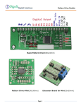
PiiGAB Ethernet/M-Bus Gateway 900 V2 Description User Manual www.PiiGAB.com ETHERNET / M-BUS Gateway 900 Description User Manual PiiGAB Process Information i Göteborg AB Anders Carlssons gata 1, S-417 55 Göteborg, Sweden Phone +46 (0)31 55 99 77, Fax +46 (0)31 22 70 71 All rights reserved. PiiGAB are registered trademark of Processinformation i Göteborg AB. Microsoft and Windows are either trademarks or registered trademarks of Microsoft Cooperation in the United States and other countries. All other trademarks are the property of their respective owners. Contents 1 GENERAL INFORMATION ........................................................................................ 3 1.1 1.2 1.3 2 ABOUT HIS MANUAL ...................................................................................................... 3 FUNCTIONAL OVERVIEW ................................................................................................ 3 ADVANTAGES AND POSSIBILITIES .................................................................................. 3 TECHNICAL STRUCTURE ........................................................................................ 4 2.1 CONNECTIONS ................................................................................................................ 4 2.2 INDICATIONS .................................................................................................................. 6 2.2.1 Placement of leds .................................................................................................... 6 2.3 RESET BUTTON ............................................................................................................... 7 2.4 TECHNICAL DATA .......................................................................................................... 7 2.5 M-BUS SPECIFICATIONS................................................................................................. 8 2.6 ETHERNET 1 CONNECTION ............................................................................................. 8 2.7 DRAWINGS ..................................................................................................................... 9 3 GET STARTED STEP BY STEP ............................................................................... 10 3.1 IMPORTANT INFORMATION ........................................................................................... 10 3.1.1 Hardware address................................................................................................. 10 3.1.2 IP Address ............................................................................................................. 10 3.1.3 TCP/UDP .............................................................................................................. 11 3.1.4 Port number .......................................................................................................... 11 3.2 USING THE M-BUS WIZARD ......................................................................................... 11 3.3 ADJUSTMENTS FOR TCP/UDP AND PORT NUMBER ...................................................... 11 3.4 COMMUNICATION TOWARDS METERS........................................................................... 12 3.4.1 Test the PiiGAB 900 like an M-Bus meter ............................................................ 12 3.4.2 The correct baud rate............................................................................................ 12 3.4.3 Adjusting the meter’s baud rate ............................................................................ 13 3.4.4 Manufacture specific configuration software ....................................................... 13 3.4.5 Important parameter adjustments ......................................................................... 13 4 M-BUS WIZARD ......................................................................................................... 14 4.1 STARTING THE M-BUS WIZARD ................................................................................... 14 4.2 FINDING THE GATEWAY ON THE NETWORK .................................................................. 15 4.3 WEB INTERFACE........................................................................................................... 17 4.4 BASE CONFIGURATION ................................................................................................. 17 4.5 MASTER PORT CONFIGURATION ................................................................................... 18 4.6 PORT 1-4 CONFIGURATION ........................................................................................... 18 4.7 COMMUNICATIONS TEST (PING) ................................................................................... 19 4.8 METER INSTALLATIONS ............................................................................................... 20 4.9 FINDING METERS ON AN M-BUS LOOP.......................................................................... 24 4.9.1 Finding meters through primary address ............................................................. 24 4.9.2 Step by step instruction for primary address search ............................................. 24 4.9.3 Finding meters through secondary address .......................................................... 25 4.9.4 Step by step instruction for secondary address search ......................................... 25 T H E M O D E R N M - B U S T E C H N O L O G Y 1 Chapter 1 General information 1.1 About his manual This manual will give you the guidance to install and connect the PiiGAB 900 to your network as well as to configure the module after your specific desires. 1.2 Functional overview The PiiGAB 900 works as an interface between the Ethernet/RS232/RS485/M-Bus slave entrance and the M-Bus loop. The gateway is completely transparent which means that the MBus questions asked via Ethernet are transferred out on the electric M-Bus interface. The same goes for the answers sent from the meters via the gateway. 900M.E.1.12 1.3 Advantages and possibilities The possibility to choose between TCP/IP or UDP/IP. The gateway can be used with a solid or a dynamic IP number. It is not dependent on any specific operating system, which means it can be used with both Linux and Windows. There is a possibility to protect it with a password to prohibit unauthorized to change the configuration. Communicate with up to four clients at once. Read M-Bus meters via Modbus (TCP/RTU). Not described in this manual. Local and central reading of the same meter from different directions at once. Connect to existing M-Bus network. Makes it possible for redundant communication. Read meters via M-Bus and Modbus at the same time. Read a few M-Bus meters without external M-Bus drivers via ASCII. Not described in this manual. Makes it possible to connect two independent networks. Can be upgraded via software key. 3 T H E M O D E R N M - B U S T E C H N O L O G Y 2 Chapter 2 Technical structure The gateway’s interface consists of one Ethernet connection, one RS232, one RS485, two parallel M-Bus slave entrance connections, four parallel outputs for M-Bus loops as well as a voltage connection. There are ten leds on the front of the gateway with different kinds of information please see the table in section 2.2 for more information. An extra Ethernet card can be chosen additionally. However, this addition will be available in the fall of 2012/2013. 2.1 Connections 900M.E.1.12 The connections on the upper 18 pins screw terminal are as stated in the below table 2-1 Connection Term Description 1 Relay NO Relayoutput normally open (can be used in the later version of the PiiGAB 900) 2 Relay COM Relayoutput (can be used in the later version of the PiiGAB 900) 3 Relay NC Relayoutput normally closed (can be used in the later version of the PiiGAB 900) 4 IN1 + Digital input no 1 (can be used in the later version of the PiiGAB 900) 5 IN1 - Digital input no 1 (can be used in the later version of the PiiGAB 900) 6 IN2 + Digital input no 2 (can be used in the later version of the PiiGAB 900) 7 IN2 - Digital input no 2 (can be used in the later version of the PiiGAB 900) 8 RS485 A Connection for RS485 9 RS485 B Connection for RS485 10 RS232 Tx Connection for RS232 Tx 11 RS232 Rx Connection for RS232 Rx 12 RS232 GND Connection for RS232 GND 13 X Not used 14 X Not used 4 T H E M O D E R N M - B U S T E C H N O L O G Y 15 M-Bus Slave + Connection to already existing M-Bus loop with belonging M-Bus master. Not connected to the PiiGAB 900 masterport. Polarity independent 16 M-Bus Slave - Connection to already existing M-Bus loop with belonging M-Bus master. Not connected to the PiiGAB 900 masterport. Polarity independent 17 M-Bus Slave + Connection to already existing M-Bus loop with belonging M-Bus master. Not connected to the PiiGAB 900 masterport. Polarity independent 18 M-Bus Slave - Connection to already existing M-Bus loop with belonging M-Bus master. Not connected to the PiiGAB 900 masterport. Polarity independent Connections on the lower left 3 pole connector are as stated in the below table: Table 2-2 Connection Term Description 1 24 V AC/DC+ 24V AC power alternatively 24V DC (plus side) 2 24 V AC/DC- 24V AC power alternatively 24V DC (minus side) 3 X Not used Connections on the lower right 9 pole connector are as stated in the below table: Table 2-3 Term Description 1 M-Bus Master + Connection to the M-Bus loop 2 M-Bus Master - Connection to the M-Bus loop 3 M-Bus Master + Connection to the M-Bus loop 4 M-Bus Master - Connection to the M-Bus loop 5 M-Bus Master + Connection to the M-Bus loop 6 M-Bus Master - Connection to the M-Bus loop 7 M-Bus Master + Connection to the M-Bus loop 8 M-Bus Master - Connection to the M-Bus loop 9 X Not used 900M.E.1.12 Connection 5 T H E 2.2 M O D E R N M - B U S T E C H N O L O G Y Indications Description of the different front leds: Row1 Description Row2 Pwr -Power led is red when normal C1 Description -Flashes red and green at the start. This usually takes 7 seconds from that the power is turned on. -Flashes red at a fast rate when there is a short circuit on the MBus loop -Flashes orange at a slow speed when over loaded C2 Information concerned configuration etc, not yet implemented C3 Information concerned configuration etc, not yet implemented M (Tx) Flashes when the Master port sends data M (Rx) Indicates when the Master port receives data P1 (Rx) Flashes when Slave port 1 receives data P1 (Tx) Flashes when Slave port 1 sends data P2 (Rx) Flashes when Slave port 2 receives data P2 (Tx) Flashes when Slave port 2 sends data P3 (Rx) Flashes when Slave port 3 receives data P3 (Tx) Flashes when Slave port 3 sends data P4 (Rx) Flashes when Slave port 4 receives data P4 (Tx) Flashes when Slave port 4 sends data Placement of leds 900M.E.1.12 2.2.1 6 T H E M O D E R N 2.3 M - B U S T E C H N O L O G Y Reset button There is a reset button between the connection for supply voltage and Ethernet1. This button has different functions that are all described below. Table 2-3 Term Action Description Restart Push the button 1 time and wait for the P1/Tx led to flash quickly. Then push the button an additional time while it is blinking. The gateway will restart. Reset of Ethernet 1 Push the button 5 times and wait for the P4/Rx led to flash quickly. Then push the button one additional time while it is blinking. The gateway’s Ethernet 1 port returns to its original settings. DHCP and randomized IP if there is no DHCP server available, see chapter 3.2 Reset of logging Push the button 6 times and wait for the P3/Rx led to flash quickly. Then push the button one additional time. While it is blinking. If a password has been chosen for the login it will now return to Admin:Admin. 2.4 Technical data Supply voltage 24V AC/DC Rated current 350mA (24V AC, 60 slaves) 250mA (24V AC, 5 and 20 slaves) Operating temperature -20°C till +55°C -35°C till +70°C Dimension WxHxD 107.6 x 90 x 62.2 Weight 220 g Protection type IP 20 Emission EN 50 022 class B radiation, EN 50 022 class B conducted Immission EN 61 000-4-2, EN 61 000-4-6 ENV 50 140, ENV 50 240, IEC 1000-4-2 900M.E.1.12 Storage temperature 7 T H E 2.5 M O D E R N M - B U S T E C H N O L O G Y M-Bus Specifications Communication speed 300 – 9600 bps (Normally 300 or 2400 bps) Voltage ground level (”1”) 40V (±1V) Voltage zero level (”0”) 28V (±1V) Short circuit level 210 mA Internal resistance <100 Ohm Number of units 5/20/60/120 (1.5mA loads/unit) 2.6 Ethernet 1 connection Communication speed Connector type RJ45 Male plug 900M.E.1.12 Female socket 300 – 230000bps 8 T H E 2.7 M O D E R N M - B U S T E C H N O L O G Y Drawings Figur 2-1 Cabinet Dimensions and tolerance in accordance with DIN43880. 900M.E.1.12 Outer measurements: W x H x D 107.6 x 90 x 62.2 9 T H E M O D E R N M - B U S T E C H N O L O G Y 3 Chapter 3 Get started step by step This chapter covers the different steps needed to put the M-Bus 900 gateway into operation. 3.1 Important information 1) Connect the PiiGAB 900 to power supply and Ethernet1 as shown in table 2.1 2) Start and wait for the Pwr led to be solid red. 3) Read out the hardware/MAC address to be found on the right end. It has the format E8-99-5A-XX-XX-XX 4) Start PiiGAB M-Bus Wizard on your PC. 5) For initial contact with the PiiGAB 900 there are three possibilities depending on what your network looks like. a) DHCP: You should be able to find your PiiGAB 900 directly via the Wizard’s ”Find gateways on your network”. b) Direct connection: Set your computer to static IP-address 192.168.10.1 and connect it directly to the PiiGAB 900. Turn on the power of the PiiGAB 900 and wait for about a minute. The gateway should get a random IP-address between 192.168.10.3 192.168.10.253. You can now use the Wizard’s ”Find gateways on your network” to find your PiiGAB 900 in the list. c) Static network: Turn on the power on the PiiGAB 900 and wait for about a minute. The unit should now receive a random IP-address within 192.168.10.3 - 192.168.10.253. Start/Restart the Wizard and click on ”Change gateway IP-settings”, click ”Next” Write the MAC-address for your PiiGAB 900, Click ”Next” Write your preferred IP-address, Click ”Next”, Click ”Apply”. The PiiGAB 900 will now restart. Netmask and Gateway is set by the web interface. Only the network address will be set. Netmask will be 255.255.255.0 which means that the IP-address must be on the same subnet as your PC. The PiiGAB M-Bus Wizard will now complain that the PiiGAB 900 does not answer. Don’t worry about this instead go to ”Find gateways on your network” and make your final settings in the web browser. 6) Open up a web browser and go to the PiiGAB 900 7) Accept the PiiGAB 900 security exceptions. 8) Log into the PiiGAB 900 with default login Username: Admin, Password: Admin You should now be in the configuration web interface of your PiiGAB 900. 900M.E.1.12 3.1.1 Hardware address You have to know the unit’s hardware address, which is the same as the MAC address. The MAC address can be found on the label on the right gable of the unit. It has the format E8-99-5A-xx-xx-xx, where xx is a unique number for the unit. 3.1.2 IP Address Most of the time the gateway needs a unique IP address on your network in order to be connected to the superior software. You can also use the automatic IP address via DHCP if you 10 T H E M O D E R N M - B U S T E C H N O L O G Y wish. Contact the system administrator to receive the right IP address with the belonging subnet mask and gateway. The IP address has to be within the allowed area, unique within your network, and it has to be in the same subnet as your PC. 3.1.3 TCP/UDP To communicate with the superior software you have to choose between TCP or UDP. 3.1.4 Port number To communicate with the gateway the port number has to be adjusted. The default adjustment in the gateway is 10001, 10002, 10003, 10004 and can almost always be used. Control with the network responsible what port number to use. 3.2 Using the M-Bus Wizard By using the M-Bus Wizard it’s possible to find the PiiGAB 900 on the network. The M-Bus Wizard is a software that can be downloaded from PiiGAB’s website. No other configuration can be done via the M-Bus Wizard instead it’s done via the web interface inside the PiiGAB 900. In the Wizard it is possible to search for the PiiGAB 810 as well as the PiiGAB 900 on your network. Usually there is an IP address appearing on the gateway and if it is outside the allowed range it will be marked in red. However, it is not possible to find the gateway if it’s connected on a subnet. 3.3 Adjustments for TCP/UDP and port number 900M.E.1.12 The web interface is used to make adjustments to TCP as well as UDP 11 T H E M O D E R N M - B U S T E C H N O L O G Y 3.4 Communication towards meters 3.4.1 Test the PiiGAB 900 like an M-Bus meter This small test is usable to get to know the PiiGAB 900, but can also be used for troubleshooting. 1) Scroll in the web interface of the PiiGAB 900 and go to ”Administration” and control that you have a valid license. 2) Scroll to the Configuration -> Master port Default: Serial, 2400 baud, 8E1, M-Bus Master 3) Scroll to Configuration -> Slaveport 1 Deafult: UDP, port 10001, M-Bus 4) Start the Wizard and find your PiiGAB 900 on the network. 5) Choose”Test, search and configure meters with M-Bus” Choose port number 10001 and UDP. 6) Set ”Primary address:” to 251, which is the internal meter in the PiiGAB 900. 7) Choose”Read meter’s first telegram” and click”Read”. The unit should now respond with its internal telegram. 8) Connect a meter and change ”Primary address” to the meter’s primary address or change it to test and diagnostics address 254. Click ”Read” and wait for the answer. 3.4.2 The correct baud rate 900M.E.1.12 After the correct IP address has been established the M-Bus loop’s baud rate has to be adjusted. The baud rate adjusted in the web interface has to match the meters baud rate. Some meters have a baud rate of 300bps at delivery. If there is a possibility to set the meters at 2400bps try to do so in order to increase the baud rate and by that improve the performance. When communication towards the meters has been established you also know that the M-bus loop is connected correctly, and you can continue to configure the superior software. 12 T H E 3.4.3 M O D E R N M - B U S T E C H N O L O G Y Adjusting the meter’s baud rate Via the M-Bus Wizard you can control the meter on your M-Bus loop directly via the meter’s primary address and secondary address. You can also adjust functions such as baud rate and primary address via your network. Note that some meter brands do not support the possibility to change for example the primary address via a standard M-Bus command. 3.4.4 Manufacture specific configuration software If you want to configure the meters via the meter manufacturer’s own software you can normally do so over the network via the gateway. 3.4.5 Important parameter adjustments Some issues to keep in mind regarding communication between the meter and the superior software is: The time interval between the questions. The number of telegrams that can be read out from the meter. What baud rate that has been chosen. 900M.E.1.12 Some meters have up to 40 telegrams that can be read. With an adjusted transference speed of 300bps this can take a long time. 13 T H E M O D E R N M - B U S T E C H N O L O G Y 4 Chapter Kapitel 4 M-Bus Wizard The M-Bus Wizard is software that can be downloaded from the PiiGAB website. The software helps you to find the PiiGAB 900 on the network as well as to test your M-Bus loop. Additional configuration is done via the web interface. 4.1 Starting the M-Bus Wizard Copy the zip file ”PiiGAB MBus Setup Wizard 3.0.1.zip” to the appropriate folder on your computer and open the file. Install the program by double clicking on the Setup files or go via the control panel. After the program has been installed you can start it by choosing the program in the start menu. If the installation has been done with the base settings the program can be found in the PiiGAB folder. The first time you start the program you have to choose your preferred language. It is however possible to change to another language at a later time. After the language has been chosen, the introduction picture is presented with a summary of the M-Bus Wizard usage. 900M.E.1.12 Figure 4-1 Click”Next” to proceed. 14 T H E M O D E R N 4.2 M - B U S T E C H N O L O G Y Finding the gateway on the network If you know that the gateway has an IP address that can be found via the network you will choose Find gateways on your network from the main menu. In some cases it is hard to find the gateway and this could be due to the fact that it’s on a subnet. Contact your network provider for more information. Figure 4-2 900M.E.1.12 Figure 4-3 The gateways found on the network will be displayed equivalently to the list above. Look under Type to see if it is an 810 or a 900 that has been found. Other units located during the search will be marked with a ‘?’. 15 T H E M O D E R N M - B U S T E C H N O L O G Y Figure 4-4 If the IP address is outside the allowed address range but possible to find within the network it will be indicated in the Wizard as shown above. By double clicking on the 900 line or ’Next’ a message box with the below text will appear Figure 4-4 If you choose Yes your standard web browser will start and if you choose No the below box will appear. 900M.E.1.12 Figure 4-5 16 T H E 4.3 M O D E R N M - B U S T E C H N O L O G Y Web interface When you know the IP number on the PiiGAB 900 you can open your web browser manually and write the gateway’s IP number. This will get you to the web interface on the gateway. Figure 4-3 It’s possible to do all the installations required to configure the 900 by using the web interface. 4.4 Base configuration 900M.E.1.12 Figure 4-4 17 T H E M O D E R N M - B U S T E C H N O L O G Y Here you choose to either use a fixed or a dynamic IP address. If you choose a fixed IP address; IP Number, Subnet Mask and Gateway have to be set. 4.5 Master Port configuration Click the Master Port tag to adjust information for such as baud rate, timeout etc Figure 4-5 4.6 Port 1-4 configuration Click the Slave Port 1-4 Configuration to adjust port information such as port number, baud rate, time out etc 900M.E.1.12 Figure 4-6 18 T H E 4.7 M O D E R N M - B U S T E C H N O L O G Y Communications test (Ping) Figure 4-7 The above picture will be presented after you have chosen to Ping the gateway from the main menu. Adjust the IP address you want to control on the gateway and choose “ping.” If the earlier steps in wizard have been done correctly the IP address will appear in this window. Figure 4-8 900M.E.1.12 If you establish contact using the Ping command the above communication result will show. Click “Next” to continue. 19 T H E 4.8 M O D E R N M - B U S T E C H N O L O G Y Meter installations When all previous steps have been made the gateway is ready to communicate out on the MBus loop. To get there in the Wizard please choose Test, search and configure meters. This choice makes you send a so called ”SND_NKE” question in order to test the communication as well as to zero out the meter to be able to read the first telegram. Figure 4-9 900M.E.1.12 Figure 4-10 This choice presents the meter’s primary and secondary address. If you don’t know which address the meter has used choose “test and diagnose” and you will receive information on 20 T H E M O D E R N M - B U S T E C H N O L O G Y both the primary and secondary address. Observe that the “test and diagnostics” function can only be used if a meter is connected to the M-Bus loop. Some meters don’t support secondary addressing, however information about the secondary address can usually be read by the meter. Figure 4-11 Below is an example of when the meter responds. 900M.E.1.12 Figure 4-12 There is also a possibility to change the meter’s primary address. Some meter brands don’t support the option to change the primary address with an M-Bus command. Some meters demand it to be in some kind of service mode. Check with the meter manufacturer for specifics. 21 T H E M O D E R N M - B U S T E C H N O L O G Y Figure 4-13 This choice makes it possible to change the baud rate. When the meter is updating you will receive a message when it has been successfully updated. Some meters respond faster than the M-Bus standard claims so sometimes you will not receive the message although it has been successfully updated. If that is the case try to test at the new baud rate to see if the meter has been updated. It is very important to do a test read on the new baud rate no matter what since some meters change back to the original baud rate if no reading has been done. 900M.E.1.12 Figure 4-14 Here the first part of the meter can be read. 22 T H E M O D E R N M - B U S T E C H N O L O G Y Figure 4-15 A read can look like this. Figure 4-16 900M.E.1.12 Some meters use ”Application reset” instead of or in combination with SND_NKE in order to zero out the meter to be able to read the first telegram. In some cases a sub code is needed together with ”Application reset” which also can be chosen with the Wizard. 23 T H E M O D E R N 4.9 M - B U S T E C H N O L O G Y Finding meters on an M-Bus loop Finding meters on an M-Bus loop by the PiiGAB 900 can be done with primary addressing or secondary addressing. If you have many meters with the same primary address you will get a collision indication. To be able to separate these meters you will need to use to secondary addressing. 4.9.1 Finding meters through primary address When using primary addressing a SND_NKE is first sent and if a meter responds a REQ_UD2 is sent to read out the meter information. Some meter do not like to first get a SND_NKE and directly after a REQ_UD2, therefore you can cancel the SND_NKE question. The search will then take a little longer since a timeout is required between each question. To make the search more effective you can set the interval of the primary address if you know that your meters should be within a certain area. Bild 4-17 4.9.2 Step by step instruction for primary address search Finding 1. 2. 3. M-Bus meters on the M-Bus loop using primary addressing. Specify the baud rate on the M-Bus loop. State what type of questions of ”SND_NKE” or ”REQ_UD2” to be used. State the first and the last primary address for the search. Click ”Start search” 900M.E.1.12 4. 24 T H E M O D E R N 4.9.3 M - B U S T E C H N O L O G Y Finding meters through secondary address When secondary addressing is used a so called binary tree is used. This can partly be followed in the search window. Bild 4-188 Step by step instruction for secondary address search Finding 1. 2. 3. M-Bus meters on the M-Bus loop using secondary addressing Specify the baud rate on the M-Bus loop. Specify if necessary your own search pattern for secondary addressing. Click ”Start search”. 900M.E.1.12 4.9.4 25