1
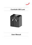
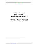
Ventilation system ComfoAir Luxe User document Heating Cooling Fresh Air Clean Air ComfoAir 160 ComfoAir 200 ComfoAir 350 ComfoAir 450 ComfoAir 550 1 - EN Foreword The following information can be found in this document: Read this document carefully before use. Information General information about the ventilation system. 1 Safety instructions which must be followed. 1 Operating devices available for the unit. 2 A summary of all the different parameters (P-menus). 2 Warranty and liability conditions. 3 What to do with the unit at the end of its life. 3 The following pictograms are used in this document: EEC declaration of conformity. 3 How to replace the filters of the unit. 4 How to clean the valves of the ventilation system. 4 When the installer or maintenance mechanic must come by for the maintenance of the unit. 4 What to do in event of an malfunction. 5 Point of attention. Chapter This document provides all the information required for safe and optimal operation and maintenance of the ComfoAir 160, 200, 350 or 550. In this document it will be referred to as “the unit”. The unit is subject to continuous development and improvement. As a result, the unit may slightly differ from the descriptions. Risk of: - damage to the device; - p erformance of the device is compromised if instructions are not observed carefully. Risk of personal injury for the user. Maintenance Questions Please contact the supplier if you have any questions or would like to order a new document or new filters. The contact details of the main supplier can be found on the rear flap of this document. All rights reserved. This documentation has been compiled with the utmost care. The publisher cannot be held liable for any damage caused as a result of missing or incorrect information in this document. In case of disp utes the English version of these instructions will be binding. EN - 2 Table of Contents Foreword.................................................................................................................................................................... 2 1 Introduction and safety............................................................................................................................................. 5 2Operation................................................................................................................................................................... 6 2.1 Available operating devices.................................................................................................................................. 6 2.2 P menus for the user............................................................................................................................................ 7 3 CE certification and warranty.................................................................................................................................. 8 4 Maintenance ........................................................................................................................................................ 9 4.1 Cleaning or replacing the filters ..................................................................................................................... 9 4.1.1Replacing the internal filters ................................................................................................................. 10 4.1.2Cleaning the internal filters .................................................................................................................. 11 4.1.3Replacing or cleaning the external filter 4.2Cleaning the valve 4.3 Condensation drain ............................................................................................... 11 ........................................................................................................................................ 11 ...................................................................................................................................... 11 4.4 Maintenance by the installer or maintenance mechanic ............................................................................... 11 5Malfunctions............................................................................................................................................................ 11 ICommissioning & Inspection Record.................................................................................................................... 12 II Maintenance log...................................................................................................................................................... 13 3 - EN EN - 4 1 Introduction and safety Safety instructions A lways follow the safety regulations, warnings, comments and instructions given in this document. Personal injury or damage to the unit can arise from non-compliance with the safety regulations, warnings, comments and instructions in this document. It is recommended to take out a maintenance contract so that the device is checked on a regular basis. The supplier can provide a list of registered installers nearby; T he unit may only be installed, connected, rendered operational and maintained by an appropriately approved installer, unless otherwise indicated in this document; S tore the document for the entire working life of the unit; Instructions with regard to cleaning or replacing the filters must be carefully observed; W hen carrying out any work on the unit, make sure the power is disconnected and cannot be inadvertently reconnected; T he unit cannot be opened without using tools. he unit is a balanced ventilation system with heat T recovery in order to create energy-efficient ventilation in houses. Balanced ventilation means that pollutants from the kitchen, the bathroom, the toilet(s) and possibly the storage room are extracted, while the same amount of fresh air is blown into the living room and bedrooms. Gaps under or near the doors ensure a good through-flow in the dwelling. Ensure that the gaps under or near the door are never obstructed. For example by furniture, draught excluders or deep-pile carpet. A balanced ventilation system consists of: The unit (A); Duct system for the supply of outdoor air (B); Duct system for the exhaust of indoor air (C); S upply valves in the living room and bedrooms (D); E xhaust valves in the kitchen, bathroom, the toilet and (if present) the storage room (E). C B A D E E E D D 5 - EN 2Operation How to use and read the operating devices of the unit is mentioned in the document of the operating device. 2.1Available operating devices One or more of the following operating devices can be present to operate the unit: Appearance Name Functions Bathroom switch Activating the overrun timer. RFZ Set the desired ventilation level: ■ 1 = Low; ■ 2 = Normal; ■ 3 = High; = Overrun timer. ■ Indicating a malfunction or filter alert. ComfoSense Indicating and setting the desired ventilation level: = Absent ■ = Low; ■ = Normal; ■ = High; ■ ■ PARTY TIMER = Overrun timer; ■ AUTO = Preset programme. Indicating a malfunction or filter alert; Indicating if the bypass, pre heater, ComfoFond-L, ComfoHood**, preset programme, analogue programme or overrun timer is activated; Turning the supply and/or exhaust fan on and off; Turning the ComfoHood** on and off; Indicating and setting the comfort temperature; Setting the P-menus; Resetting the malfunctions and filter alert; Setting a preset ventilation programme; Setting and showing date and time. CC Luxe** Indicating and setting the desired ventilation level: ■ A = Absent ■ 1 = Low; ■ 2 = Normal; ■ 3 = High; = Overrun timer; ■ = Preset programme. ■ Indicating a malfunction or filter alert; Indicating if the bypass, pre heater, ComfoFond-L, ComfoHood**, preset programme, analogue programme or overrun timer is activated; Indicating outside and inside temperatures; Turning the supply and/or exhaust fan on and off; Turning the ComfoHood** on and off; Indicating and setting the comfort temperature; Setting the P-menus; Resetting the malfunctions and filter alert; Setting a preset ventilation programme; Setting a preset comfort temperature programme; Setting and showing date and time; Setting languages and screen configuration. CO 2 sensor Indicating and setting the desired ventilation level: ■ I = Low; ■ II = Normal; ■ III = High; ■ Auto = Automatic (according to measured CO 2 level); Indicating the CO 2 level. ** Only available on the ComfoAir350Luxe, ComfoAir450Luxe and ComfoAir550Luxe. EN - 6 2.2 P menus for the user A summary of all the accessible P-menus is given below. Menu P1 > Status of time programmes Menu P9 > Status of additional programmes Status Status Submenu Description Activated Submenu Description Activated Open fire programme active? Yes (1) / No (0) P10** Is menu P20 currently active? Yes (1) / No (0) P90 P91 Bypass open? Yes (1) / No (0) P11 Is menu P21 currently active? Yes (1) / No (0) P92** ComfoFond-L** valve open? Yes (1) / No (0) P12 Is menu P22 currently active? Yes (1) / No (0) P93** Post heater on? Yes (1) / No (0) P13 Is menu P23 currently active? Yes (1) / No (0) P94 Analogue input (0-10V) active? Yes (1) / No (0) P14 Is menu P24 currently active? Yes (1) / No (0) P95 Frost protection or pre heater active? Yes (1) / No (0) P15 Is menu P25 currently active? Yes (1) / No (0) P96** ComfoHood** on? Yes (1) / No (0) P16 Is menu P26 currently active? Yes (1) / No (0) P99 Enthalpy programme active? Yes (1) / No (0) P19** Is menu P29 currently active? Yes (1) / No (0) Menu P2 > Setting time delays Time delay values Submenu Description Minimum Maximum General reset P20** Overrun timer for the ComfoHood** programme. ’x’ minutes after operating the ComfoHood** switch the unit reverts back to the normal setting. 0 Min. 180 Min. 0 Min. P21 Delay timer for the bathroom switch (to switch to high position). ‘ x‘ minutes after operating the bathroom switch, the unit switches to the high setting. 0 Min. 15 Min. 0 Min. P22 Overrun timer for the bathroom switch (to switch to normal position). ‘ x‘ minutes after operating the bathroom switch, the unit switches back to the normal setting. 0 Min. 120 Min. 30 Min. P23 n/a 0 Min. 120 Min. 0 Min. P24 Filter warning ‘ x’ weeks after cleaning the filters the “filter dirty” alert will reappear. 10 weeks 26 weeks 16 weeks 1 Min. 20 Min. 10 Min. 1 Min. 120 Min. 30 Min. 0 Min. 120 Min. 30 Min. 1% 99% 10% Only applies to systems fitted with a ComfoHood**. P25 Only applies to systems fitted with an RFZ swith. Overrun timer for ventilation setting 3 (using ). A fter pressing briefly (< 2 sec.), the unit will switch to the high setting for ‘x’ minutes and then automatically returns to the normal setting. If any switch is operated during this lagging time the unit will instantly revert to the ventilation position as set at that time. P26 Only applies to systems fitted with an RFZ swith. Overrun timer for ventilation setting 3 (using ). A fter pressing continously (> 2 sec.), the unit will switch to the high setting for ‘x’ minutes and then automatically returns to the normal setting. If any switch is operated during this lagging time the unit will instantly revert to the ventilation position as set at that time. Time for the boost setting. P27 Only applies to systems fitted with a ComfoSense or CC Luxe**. A fter pressing on the CC Luxe** or after turning on the PARTY TIMER on the ComfoSense, the unit will switch to the high setting for ‘x’ minutes and then automatically returns to the normal setting. If any switch is operated during this lagging time the unit will instantly revert to the ventilation position as set at that time. P29** Only applies to systems fitted with a ComfoHood**. Setting the ComfoHood** ventilation levels. W hen the ComfoHood** is switched on the ComfoHood** ventilation settings can be set x-% higher than the corresponding ‘normal’ ventilation levels. ** Only available on the ComfoAir350Luxe and ComfoAir550Luxe. 7 - EN 3 CE certification and warranty Warranty conditions The unit is covered by a manufacturer’s warranty for a period of 24 months after fitting up to a maximum of 30 months after the date of manufacture. Warranty claims may only be submitted for material faults and/ or construction faults arising during the warranty period. In the case of a warranty claim, the unit must not be dismantled without written permission from the manufacturer. Spare parts are only covered by the warranty, if they were supplied by the manufacturer and have been installed by an approved installer. The warranty becomes invalid if: The guarantee period has elapsed; The device is used without filters; Parts are used that have not been supplied by the manufacturer; N on-authorised changes or modifications have been made to the unit. Installation has not been carried out according to the applicable regulations; T he defects are due to incorrect connection, inexpert use, or contamination of the system; n-site (dis)assembly costs are not covered by the O terms of the warranty. This also applies to normal wear and tear. Zehnder retains the right to change the construction and/or configuration of its products at any time without being obliged to alter previously delivered products. Liability he unit has been designed and manufactured for T use in balanced ventilation systems incorporating Zehnder heat recovery systems. Any other application is seen as inappropriate use and can result in damage to the unit or personal injury, for which the manufacturer cannot be held liable. The manufacturer is not liable for any damage originating from: N on-compliance with the safety, operating and maintenance instructions in this document; T he use of components not supplied or recommended by the manufacturer. R esponsibility for the use of such components lies entirely with the installer; N ormal wear and tear. nd of useful life E C onsult with the supplier about what should be done with the unit at the end of its useful life. If the unit cannot be returned to the supplier, avoid disposing of it with the domestic waste, and ask your local council about the options for recycling the components or processing the materials in an environmentally friendly manner. Furthermore, do not dispose of batteries from the wireless (RF) switches with the normal waste, but bring them to the specially designated disposal locations. CE certification Zehnder Group Nederland B.V. Lingenstraat 2 • 8028 PM Zwolle-NL T +31 (0)38 4296911 • F +31 (0)38 4225694 Company register Zwolle 05022293 Machine description EEC declaration of conformity Heat recovery units: ComfoAir 160, 200, 350, 550 series Complies with the following directives Machinery Directive (2006/42/EEC) Low Voltage Directive (2006/95/EEC) EMC Directive (2004/108/EEC) Zwolle, 05.01.10 Zehnder Group Nederland B.V. E. van Heuveln, Managing Director EN - 8 4 Maintenance Failure to carry out (periodic) maintenance on the unit ultimately compromises the performance of the ventilation system. The unit should be inspected and cleaned every 2 years by a specialist. To ensure a hassle free lifespan for your unit, we recommend you take out a service agreement with an expert company. E nsure the unit has been disconnected from mains power before carrying out any maintenance work. he power to the unit should not be disconnected T unless the unit is to be taken out of service due to a serious malfunction, or for filter replacement or any other compelling reasons. I f the power to the unit is disconnected, mechanical ventilation of the dwelling will cease. This can lead to a build-up of moisture and results in problems with mould. 4.1Cleaning or replacing the filters Replace the filters (at least) every six months and clean the filters every 2 or 3 months. hen indicated on the ComfoSense or CC Luxe** W you must clean or replace the filters. The installer of the unit can provide the necessary new filters. Unit type ComfoAir 160 ComfoAir 200 Filter type Article number 2x G4 400100023 1x F7 / 1x G4 400100024 1x F7 / 1x G4 400100013 2x G4 400100014 2x F7 400100017 ComfoAir 350 2x G4 006040200 1x F7 / 1x G4 006040250 ComfoAir 550 2x G4 006040200 1x F7 / 1x G4 006040250 ** Only available on the ComfoAir350Luxe and ComfoAir550Luxe. 9 - EN 4.1.1 Replacing the internal filters Action Explanation 1 2 1 Reset the filter error as mentioned in the manual of the ComfoSense or CC Luxe**. 2 Disconnect the power from the unit. A A ComfoAir 160 ComfoAir 200 Remove the handles (A) from the unit. 3 A A A A ComfoAir 350 ComfoAir 550 4 Remove the dirty filters (B) from the unit. B ComfoAir 160/200 5 ComfoAir 350/550 Install the clean filter back into the unit and reconnect the power. When using the unit for the first time, it is recommended to replace the filters (and clean the valves) first. During the construction phase the ventilation system could have become dirty with building dust. ** Only available on the ComfoAir350Luxe and ComfoAir550Luxe. EN - 10 4.1.2 Cleaning the internal filters Vacuum the filters (B) with a vacuum cleaner instead of replacing them with new filters. When using the unit for the first time, it is recommended to clean the filters (and valves) first. During the construction phase the ventilation system could have become dirty with building dust. 4.1.3 Replacing or cleaning the external filter If so indicated on the ComfoSense or CC Luxe** you must clean or replace the filter as is mentioned in the external filter document. 4.2C leaning the valve Clean the valves (at least) twice a year. 1. Mark the setting of the valve; 2. Remove the valve from the wall or ceiling; 3.Clean the valve in a solution of soap and warm water; 4. Rinse the valve thoroughly and wipe dry; 5.Place the valve back WITH EXACTLY THE SAME SETTING (and IN THE SAME HOLE); 6.Repeat this procedure for the other valves. Some valves have a filter behind it. If a filter is present clean this in the same way as the valve. About the valve settings he ventilation air is supplied and discharged T by means of valves. Gaps under or near doors in the dwelling ensure that the air flows in the right direction. In order to ensure that the correct ventilation volumes are maintained in the rooms, the following must be observed: D o not seal the gaps under or near the doors. For example by furniture, draught excluders or deeppile carpet. The gap should be at least 2cm; Do not change the settings of the valves; Do not replace the valves with one another. T he installer will have set all the valves to ensure the optimum performance of the ventilation system. Therefore, do not change the setting of the valves. 4.3Condensation drain Ensure that the water seal (u-bend) connected to the domestic waste-water system is always full of water. 4.4Maintenance by the installer or maintenance mechanic ot all neccesary maintenance can be done by N the user. O nce every 2 years the installer or a maintenance mechanic should come by for the maintenance inside the balanced ventilation system. Some installers offer a full maintenance contract package where the user maintenance can also be integrated. 5Malfunctions In the event of a malfunction, the corresponding malfunction code will be displayed on the ComfoSense or CC Luxe** of the unit. In event of a filter malfunction the filter must be cleaned or replaced as described in the Maintenance chapter. In the event of all other malfunction: Action Explanation 1 Note down the malfunction code that appears on the ComfoSense or CC Luxe** of the unit. 2 Note down the unit type. This is given on the identification plate on the unit near the power supply. 3 Contact the installer or maintenance mechanic and give him the noted information. The system should not be disconnected from the power supply, unless the unit must be taken out of service due to a serious malfunction, or for filter cleaning/replacement or any other compelling reasons. If the unit is disconnected from the power supply, mechanical ventilation of the dwelling will cease. This can lead to a buildup of moisture and results in problems with mould. I f the unit is installed in an area with a higher average humidity (such as bathroom or toilet) the probability of condensation on the outside of the unit is high. This is similar to condensation on a window and no action is needed. ** Only available on the ComfoAir350Luxe and ComfoAir550Luxe. 11 - EN I Installation/test report Date Address Work instruction Town/city Commissioning party Project type Installed by Residence type Gemeten door Unit type Return Room Position Required [m 3 /h] Tested [m3/h] Type valve Settings valve Settings unit Kitchen P30 Bathroom P31 Toilet P32 … P33 … … Total: Supply Room Position Required [m 3 /h] Tested [m3/h] Type valve Settings valve Settings unit Living room P34 Bedroom 1 P35 Bedroom 2 P36 Bedroom 3 P37 … … … Total: Pressure Measured Press pressure Suction pressure Total: EN - 12 Supply [Pa] Return [Pa] II Maintenance log 2 or 3 months after installation: Activity Y1 Y2 Y3 Y4 Y5 Y6 Y7 Y1 Y2 Y3 Y4 Y5 Y6 Y7 Y1 Y2 Y3 Y4 Y5 Y6 Y7 Y1 Y2 Y3 Y4 Y5 Y6 Y7 Clean the filters 6 months after installation: Activity Replace the filters Clean the valves 9 months after installation: Activity Clean the filters 12 months after installation: Activity Replace the filters Clean the valves Inspect and clean the condensation drain Inspect and clean the air ducts Inspect and clean the casing of the unit Inspect and clean the heat exchanger Inspect and clean the fans Inspect and clean the pre heater filter Date Activity Initials 13 - EN 2 or 3 months after installation: Activity Y8 Y9 Y10 Y11 Y12 Y13 Y14 Y8 Y9 Y10 Y11 Y12 Y13 Y14 Y8 Y9 Y10 Y11 Y12 Y13 Y14 Y8 Y9 Y10 Y11 Y12 Y13 Y14 Clean the filters 6 months after installation: Activity Replace the filters Clean the valves 9 months after installation: Activity Clean the filters 12 months after installation: Activity Replace the filters Clean the valves Inspect and clean the condensation drain Inspect and clean the air ducts Inspect and clean the casing of the unit Inspect and clean the heat exchanger Inspect and clean the fans Inspect and clean the pre heater filter Date EN - 14 Activity Initials 15 - EN ZGNL-Manual_849050670, V1113, EN, Subject to change Zehnder Group Nederland B.V. Lingenstraat 2 • 8028 PM • Postbus 621 • 8000 AP Zwolle T +31 38 429 69 11 • F +31 38 422 56 94 [email protected] • www.zehnder-jestorkair.nl