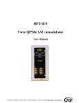
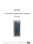
1
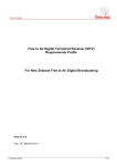
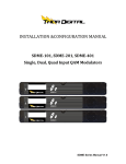
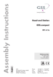
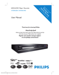
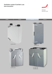
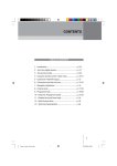
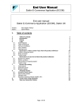
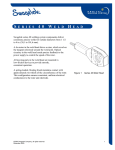
SAT-40CI
4 ch. QPSK/AM remodulator system VSB A2
Quick User Guide
1. Purpose of use
SAT-40CI is designed for a processing four QPSK modulated satellite signals into standard CCIR
channels. SAT-40CI is supplied with a A2 stereo/dual/swap dual/multistandard mono modulator, which
can be used on the adjacent channels (VSB modulation) from S2 to E69.
2. Installation
The connections and indications are shown in Fig 1.
1. Control switch: Channel 1 (3) = left or channel 2 (4)
= right. The switch must be set to middle position
when programming is ready.
2. Channel number (CCIR) or TV standard.
3. Cable-TV S channel.
4. The signal led shows that the unit is powered or
modulator set-up is activated.
5. Signal led indicates that receiver is locked to
selected transport stream.
6. LNB IN
7. USB port is for possible software update.
8. RF OUT
9. DC IN
11. VIDEO/AUDIO connectors for monitoring.
12. IR detector.
13. CAM slot.
SAT-40CI is mounted directly on the wall. Do not cover the air passage holes.
RF OUT is connected to cable network. Power supply is connected to DC connector at the bottom of
unit (9). VIDEO/AUDIO connectors (11) are for monitoring.
NOTE! CA module (13) for smart card must be installed and removed only when power is OFF.
Signals from LNB are fed to IF-connectors (6) at the top of unit.
NOTE! LNB supply voltage must be fed only from one receiver to each LNB output. For other receivers
must be selected POWER OFF (Configuration menu/LNB control mode) or RFZ-80X splitters must be
used (Fig. 2.).
RF-Tuote Oy, Telakkatie 25, 25570 Teijo, tel. +358-2736 6360, fax. +358-2-736 6360, [email protected], www.rf-tuote.fi
Fig 2.
3. Modulators set-up
The factory pre-adjusted channels are E5, E6, E7 and E8.
To control modulator first slide front panel switch to left or right position to control receiver 1 (3) or 2
(4) respectively. Press UHF key (Fig 3. no 14) on the remote. On selected output channel display a dot is
lit on right lower corner. Set up selected channel using up and down arrow keys (Fig 3. no 12 or 13). A
dot on the middle of the display shows S-channels. To select a channel press OK key (Fig 3. no 3).
To cancel selection, press EXIT key (Fig 3. no 6).
4. Channel selection
The most of programs from Astra and Hotbird satellites are saved to SAT-40CI memory places (Table
1.).
NOTE! The pre-programmed memory places are valid only for UNIVERSAL LNB.
First slide front panel switch to left or right position to control receiver 1 (3) or 2 (4) respectively.
Press MENU key (Fig 3. no 1) on the remote and select CHANNEL LIST and press OK.
You can scroll the list using up and down arrow keys (Fig 3. no 12 or 13). To scroll one page at a time,
use double arrow keys (Fig 3. no 10 or 11). You can use auto repeat by keeping a key pressed.
Info shows memory number, satellite indication (A=Astra, B=Hotbird) transponder frequency, band
information, program name and is the channel CA* or FTA*.
* CA stands for Conditional Access channel. To view a CA channel an appropriate Conditional Access
Module and a viewing card will be needed.
* FTA stands for free channel available without a Conditional Access module or a viewing card.
To confirm selection press OK key.
NOTE! WHEN PROGRAMMING IS READY, THE FRONT PANEL SWITCH MUST BE SLIDED
TO CENTER POSITION.
RF-Tuote Oy, Telakkatie 25, 25570 Teijo, tel. +358-2736 6360, fax. +358-2-736 6360, [email protected], www.rf-tuote.fi
1. MENU
2. INFO
3. OK
4. VOL <
5. VOL >
6. EXIT
7. SYS
8. F1
9. EPG
10. ∧∧
11. ∨∨
12. CH ∧
13. CH ∨
14. UHF
Main OSD menu
Channel information
Confirm selection exit from menu
Audio volume, select left
Audio volume, select right
Exit from menu
UHF + SYS = set TV standard
BER
Channel list
Scroll channel list one page at a time
Scroll channel list one page at a time
Change a channel, select up
Change a channel, select down
UHF + ∧/∨ = set output channel
Fig 3.
Memory place
Satellite
Transponder
Symbol rate
Polarisation
Program
24
33
93
96
108
109
321
327
331
333
340
341
360
396
Astra
Astra
Astra
Astra
Astra
Astra
Astra
Astra
Astra
Astra
Astra
Astra
Astra
Astra
11,837
11,954
12,188
12,188
12,227
12,227
11,538
11,568
11,568
11,568
11,597
11,597
11,778
11,973
27500
27500
27500
27500
27500
27500
22000
22000
22000
22000
22000
22000
27500
27500
H
H
H
H
H
H
V
V
V
V
V
V
V
V
Das Erste
ZDF
RTL Television
VOX
Eurosport
Euronews
Russia today
TVEi
TV5MONDE
RAI 1
CNBC Europe
BBC World
CNN Int.
MTV Germany
Table 1.
5. Ouput level adjustment
Select from main menu MODULATOR /OUTPUT LEVEL to adjust the output level. Output level is
adjusted with the right/left arrows. The attenuator value 0 dB refers to minimum output level and 20 dB
refer to maximum output level.
6. Adjustments without OSD
When not using the menu system you can adjust audio volume by pressing left and right VOL keys (Fig 3.
no 4 or 5) and change channels using up and down CH keys.
To open the Channel List press EPG key (Fig 3. no 9). To see current channel info press INFO key (Fig 3.
no 2).
You can also monitor satellite signal quality by pressing F1 key (Fig 3. no 8).
RF-Tuote Oy, Telakkatie 25, 25570 Teijo, tel. +358-2736 6360, fax. +358-2-736 6360, [email protected], www.rf-tuote.fi
7. Technical specification
Number of channels
4
Tuners
4
Input frequency range
950 - 2150 MHz
Input level
-70 … -25 dBm
Waveform
QPSK (SCPC, MCPC)
Symbol rate
4-45 MS/s
FEC decoder
Automatic
Transport stream
MPEG-2 ISO/IEC 13818
Teletext
Through VBI
Subtitling
DVB or teletext
CI slot
4
Output frequency range
112,25 MHz - 855,25 MHz
Modulation
AM, VSB, A2 stereo, swap dual
Transmission standard
B/G, D/K, I, L, M/N
Output level
80 - 100 dBuV
Spurious products
< 60 dBc
S/N weighted
55 dB
Data interface
4* USB 1
Input connectors
F-female 75 ohm
Output connectors
F-male 75 ohm
Power consumption
16VDC/3,5A
Dimensions
W*H*D
143mm*285mm*134mm
This symbol on the product or on its packing means that within the European Union the product must be
taken to separate collection at the product-end-of life.
Do not dispose of these products as unsorted municipal waste.
Fore more information about where you can drop off your waste equipment for recycling, please contact
your local city office, your house disposal service or the shop where you purchased the product.
RF-Tuote Oy, Telakkatie 25, 25570 Teijo, tel. +358-2736 6360, fax. +358-2-736 6360, [email protected], www.rf-tuote.fi
SAT-40CI
4 ch. QPSK/AM remodulator system VSB A2
User Manual
RF-Tuote Oy, Telakkatie 25, 25570 Teijo, tel. +358-2736 6360, fax. +358-2-736 6360, [email protected], www.rf-tuote.fi
1. Purpose of use
SAT-40CI is designed for a processing four QPSK modulated satellite signals into standard CCIR
channels. SAT-40CI is supplied with a A2 stereo/dual/swap dual/multistandard mono modulator, which
can be used on the adjacent channels (VSB modulation) from S2 to E69.
2. Installation
The connections and indications are shown in Fig 1.
1. Control switch: Channel 1 (3) = left or channel 2 (4)
= right. The switch must be set to middle position
when programming is ready.
2. Channel number (CCIR) or TV standard.
3. Cable-TV S channel.
4. The signal led shows that the unit is powered or
modulator set-up is activated.
5. Signal led indicates that receiver is locked to
selected transport stream.
6. LNB IN
7. USB port is for possible software update.
8. RF OUT
9. DC IN
11. VIDEO/AUDIO connectors for monitoring.
12. IR detector.
13. CAM slot.
SAT-40CI is mounted directly on the wall . Do not cover the air passage holes.
Power supply is connected to DC connector at the bottom of unit (9).
RF OUT (8) is connected to cable network.
VIDEO/AUDIO connectors (11) are for monitoring the unit.
NOTE! CA module (13) for smart card must be installed and removed only when power is OFF. It is
highly recommended to use recently updated smart card.
Signals from LNB are fed to IF-connectors (6) at the top of unit.
NOTE! LNB supply voltage must be fed only from one receiver to each LNB output. For other receivers
must be selected POWER OFF (Configuration menu/LNB control mode) or RFZ-80X splitters must be
used.
3. Programming
The receivers and modulators are simple to program with the remote control unit (RCU). The main
functions of RCU are shown in Fig 2.
RF-Tuote Oy, Telakkatie 25, 25570 Teijo, tel. +358-2736 6360, fax. +358-2-736 6360, [email protected], www.rf-tuote.fi
15. MENU
16. INFO
17. OK
18. VOL <
19. VOL >
20. EXIT
21. SYS
22. F1
23. EPG
24. ∧∧
25. ∨∨
26. CH ∧
27. CH ∨
28. UHF
Main OSD menu
Channel information
Confirm selection
Audio volume, select left
Audio volume, select right
Exit from menu
UHF + SYS = set TV standard
BER
Channel list
Scroll channel list one page at a time
Scroll channel list one page at a time
Change a channel, select up
Change a channel, select down
UHF + ∧/∨ = set output channel
Fig 2.
NOTE! When programming is ready the switch must be set to center position.
3.1 Power-up
At power-up this welcome screen is displayed. Receiver and user interface version numbers plus unit serial
number are shown.
When the unit is powered the display lights up showing selected output channels (Fig 1. no 2 ). The factory
set channels are E5, E6, E7 and E8.
The display is switched off after 3 minutes. The signal leds (Fig. 1. no 4) indicate that the unit is powered.
The display lights up again by pressing any button of remote controller unit.
Next program info for channel previously selected is displayed and the channel opened, if possible. Info
shows satellite number i.e. DiSEqC switch control, transponder frequency, data rate, FEC and channel video
PID number. Please note that opening a channel will take longer time when a conditional access module is
inserted. It is recommended to use updated smart card. If the channel list is empty, welcome screen will
remain displayed.
RF-Tuote Oy, Telakkatie 25, 25570 Teijo, tel. +358-2736 6360, fax. +358-2-736 6360, [email protected], www.rf-tuote.fi
3.2 First time set-up
When using the unit for the first time, you must first set the modulator output to required channel. After this
you can continue set-up using on-screen menus.
To control modulator first slide front panel switch to left or right position to control receiver 1 (3) or 2 (4)
respectively. Press UHF key (Fig 2. no 14) on the remote. On selected output channel display a dot is lit on
right lower corner (Fig 1. no 4). This indicates that modulator set-up is activated. Test pattern and test sound
are switched on.
To change output channel press up or down CH keys (Fig 2. no 12 or 13) to scroll thought available
channels. Cable TV S-channels are indicated with a dot between digits (Fig 1. no 3). The selectable channels
are S02 - S10, 5 - 12, S11 - S41 and 21 – 70 (CCIR).
To change TV standard press SYS key (Fig 2. no 7) repeatedly until required standard name (BG, I, DK, L
or MN) is displayed.
To save modulator settings press OK key (Fig 2. no 3). To cancel selection, press EXIT key (Fig 2. no 6).
Modulator set-up will be exited and test pattern and test sound will be switched off in both cases.
3.3 Set-up
To start set-up, press Menu key (Fig 2. no 1). Main Menu will be displayed.
If channels are already stored, select “Channel List” and press OK.
On channel list all stored channels are listed with sequence number, satellite indication (see
Configuration/Menu/Add Default Channels), transponder frequency and band information. After channel
program name on right column channel status is shown. “FTA” stands for free channel available without a
Conditional Access module or a viewing card. “CA” stands for Conditional Access channel. To view a CA
channel an appropriate Conditional Access Module and a viewing card will be needed. This information is
only normative and can be missing in some cases.
You can scroll the list using up and down arrow keys (Fig 2. no 12 or 13). To scroll one page at a time, use
double arrow keys (Fig 2. no 10 or 11). You can use auto repeat by keeping a key pressed.
To select a channel press OK key. Menu will be closed and channel opened, if possible. To exit without
selecting any channel press EXIT key.
RF-Tuote Oy, Telakkatie 25, 25570 Teijo, tel. +358-2736 6360, fax. +358-2-736 6360, [email protected], www.rf-tuote.fi
In main menu, select “SW Version Info” and press OK to display receiver and user interface version
numbers plus unit serial number info.
Most of the system set-up is done in Configuration Menu. Select “Configuration” and press OK to enter.
You can select the audio language in two ways. Firstly you can select from preset languages selecting
“Audio Language” and using left and right arrow keys ( Fig 2. no 4 or 5) to select the language name.
Secondly if your language is not among the preset languages you can freely write any 3-character language
name. Use double arrow keys (Fig 2. no 10 or 11) to select character position, which will be underlined, and
select needed character using up and down keys (Fig 2. no 12 or 13). Use double arrow keys to exit edit
with no character underlined.
RF-Tuote Oy, Telakkatie 25, 25570 Teijo, tel. +358-2736 6360, fax. +358-2-736 6360, [email protected], www.rf-tuote.fi
You can also select subtitle language in a similar manner or you can select OFF to turn off subtitling.
Front-end control can be adjusted by selecting “Front-end Control Mode” and using left and right arrow
keys to select appropriate mode. This mode is used in “Scan Satellite” task as well as in normal operation.
In “LNB Control Mode” you can select normal or fixed control using left and right arrow keys.
All selectable options in Configuration Menu are shown below.
To scan satellites select “Scan Satellite” and press OK key.
RF-Tuote Oy, Telakkatie 25, 25570 Teijo, tel. +358-2736 6360, fax. +358-2-736 6360, [email protected], www.rf-tuote.fi
If any of the one band front-end control modes is selected, only that band will be scanned. For low band,
frequencies from 10700 to 11700 MHz will be scanned. For high band, frequencies from 11700 to 12700
will be scanned. If “LNB Control Mode” is set to “Normal”, appropriate control voltage and 22 kHz control
is output to LNB. If “Power Off” is selected there is no voltage at output. This is useful when splitters are
used to feed LNB signal to several receivers.
When “Universal LNB” is selected then all four bands of a universal LNB will be scanned automatically
using voltage and 22 kHz control. When “Toneburst” is selected then two universal LNBs will be scanned
using toneburst switch control. When “DiSEqC 1.0” is selected then four universal LNBs will be scanned
using DiSEqC switch control.
You can monitor the search at lower part of the display.
As satellite search will take considerable amount of time, you can to scan only one transponder if you know
the parameters. To do this, select “Scan Transponder” and press OK key.
You can adjust transponder frequency using numeric keys, left and right keys or double arrow keys.
You can select Symbol Rate from preset values using left and right arrow keys or select “Auto” to try all
these preset values. You can also enter any symbol rate using numeric keys or double arrow keys.
FEC can be set to “Auto” or any fixed value using left and right keys. Polarization is also selected using left
and right keys. Sat ID will be used in channel information and to control DiSEqC switch.
When using non-universal LNBs, you can adjust the local oscillator frequency values accordingly.
All selectable options in Scan Transponder Menu are shown below.
RF-Tuote Oy, Telakkatie 25, 25570 Teijo, tel. +358-2736 6360, fax. +358-2-736 6360, [email protected], www.rf-tuote.fi
To scan the transponder select “Scan” and press OK key.
Press EXIT key, if you want to exit without scanning transponder. In this case settings are stored even you
do not scan transponder.
In configuration menu, to clear all channels from channel list select “Clear Program List” and press OK
Key. “Program list cleared” appears on the display after channels are removed.
In “Add Default Channels” menu you can add channel lists of different satellites according to region
(European, Nordic or British). Select region with the left or right arrow key and press OK key to confirm
region. In the channel list the satellite is indicated as following. European A=Astra, B=Hotbird, Nordig:
A=Thorn, B=Sirius.
RF-Tuote Oy, Telakkatie 25, 25570 Teijo, tel. +358-2736 6360, fax. +358-2-736 6360, [email protected], www.rf-tuote.fi
To exit menu press EXIT key. The settings you made will be saved and “User settings saved” appears on the
display.
In main menu, to adjust modulator, select “Modulator” and press OK.
You can select output channel using left and right arrow keys. The channel number will be displayed
simultaneously on front panel display. The selectable channels are S02 - S10, 5 - 12, S11 - S41 and 21 – 69
(CCIR).
You can select the TV standard using left and right keys and audio output for BG standard. “Mono” is
standard audio. “Stereo” and “Dual” use dual tone coding system to transmit two audio channels. “Dual
Swap” reverses the main and secondary audio. For standards other than BG only mono can be used.
RF-Tuote Oy, Telakkatie 25, 25570 Teijo, tel. +358-2736 6360, fax. +358-2-736 6360, [email protected], www.rf-tuote.fi
All selectable options in Modulator Menu are shown below.
To adjust modulator output attenuation use left and right arrow keys. You can fine tune output frequency
when using different channel grid than CCIR. Adjustment is done using left and right arrow keys in steps of
250 kHz. Adjustment range is ± 4 MHz. You can monitor the adjusted frequency in parenthesis on the same
line.
Press EXIT key to exit menu. The settings you made will be saved.
To select menu language, select “Menu Language” and press OK. You can select the menu language using
left and right keys.
Press EXIT key to exit menu. The settings you made will be saved.
3.4 Normal operation
When not using the menu system you can adjust audio volume by pressing left and right VOL keys (Fig 2.
no 4 or 5) and change channels using up and down CH keys.
To open the Channel List press EPG key (Fig 2. no 9). To see current channel info press INFO key (Fig 2.
no 2). You can also monitor satellite signal quality by pressing F1 key (Fig 2. no 8).
Press EXIT key to close this display. When programming is ready, the front panel switch must be slided to
center position. This will prevent accidental changes to be made while controlling other units. The display,
exept two leds, are switched off in 6 minutes after programming is finished.
RF-Tuote Oy, Telakkatie 25, 25570 Teijo, tel. +358-2736 6360, fax. +358-2-736 6360, [email protected], www.rf-tuote.fi
4. Technical specification
Number of channels
4
Tuners
4
Input frequency range
950 - 2150 MHz
Input level
-70 … -25 dBm
Waveform
QPSK (SCPC, MCPC)
Symbol rate
4-45 MS/s
FEC decoder
Automatic
Transport stream
MPEG-2 ISO/IEC 13818
Teletext
Through VBI
Subtitling
DVB or teletext
CI slot
4
Output frequency range
112,25 MHz - 855,25 MHz
Modulation
AM, VSB, A2 stereo, swap dual
Transmission standard
B/G, D/K, I, L, M/N
Output level
80 - 100 dBuV
Spurious products
< 60 dBc
S/N weighted
55 dB
Data interface
4* USB 1
Input connectors
F-female 75 ohm
Output connectors
F-male 75 ohm
Power consumption
16VDC/3,5A
Dimensions
W*H*D
143mm*285mm*134mm
RF-Tuote Oy, Telakkatie 25, 25570 Teijo, tel. +358-2736 6360, fax. +358-2-736 6360, [email protected], www.rf-tuote.fi
This symbol on the product or on its packing means that within the European Union the product must be
taken to separate collection at the product-end-of life.
Do not dispose of these products as unsorted municipal waste.
Fore more information about where you can drop off your waste equipment for recycling, please contact
your local city office, your house disposal service or the shop where you purchased the product.
RF-Tuote Oy, Telakkatie 25, 25570 Teijo, tel. +358-2736 6360, fax. +358-2-736 6360, [email protected], www.rf-tuote.fi