1
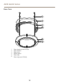
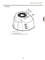
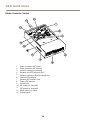
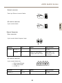
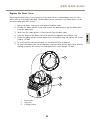
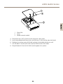
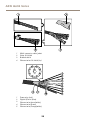
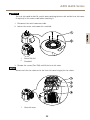
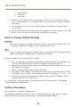
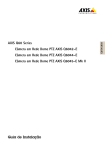
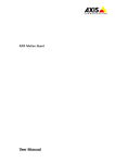
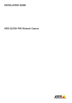
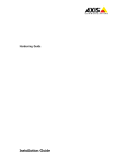
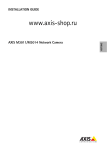
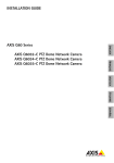
AXIS Q6042-C PTZ Dome Network Camera
AXIS Q6044-C PTZ Dome Network Camera
AXIS Q6045-C PTZ Dome Network Camera
Installation Guide
ENGLISH
AXIS Q604 Series
Legal Considerations
Regulatory Information
Video surveillance can be regulated by laws that vary from
country to country. Check the laws in your local region
before using this product for surveillance purposes.
This product includes one (1) H.264 decoder license. To
purchase further licenses, contact your reseller.
Europe
Liability
Every care has been taken in the preparation of this
document. Please inform your local Axis office of any
inaccuracies or omissions. Axis Communications AB cannot
be held responsible for any technical or typographical errors
and reserves the right to make changes to the product and
manuals without prior notice. Axis Communications AB
makes no warranty of any kind with regard to the material
contained within this document, including, but not limited
to, the implied warranties of merchantability and fitness for
a particular purpose. Axis Communications AB shall not
be liable nor responsible for incidental or consequential
damages in connection with the furnishing, performance
or use of this material. This product is only to be used for
its intended purpose.
Intellectual Property Rights
Axis AB has intellectual property rights relating to
technology embodied in the product described in this
document. In particular, and without limitation, these
intellectual property rights may include one or more of
the patents listed at www.axis.com/patent.htm and one or
more additional patents or pending patent applications in
the US and other countries.
This product contains licensed third-party software. See
the menu item “About” in the product’s user interface for
more information.
This product contains source code copyright Apple Computer,
Inc., under the terms of Apple Public Source License 2.0
(see www.opensource.apple.com/apsl). The source code is
available from https://developer.apple.com/bonjour/
Equipment Modifications
This equipment must be installed and used in
strict accordance with the instructions given in the
user documentation. This equipment contains no
user-serviceable components. Unauthorized equipment
changes or modifications will invalidate all applicable
regulatory certifications and approvals.
Trademark Acknowledgments
AXIS COMMUNICATIONS, AXIS, ETRAX, ARTPEC and VAPIX
are registered trademarks or trademark applications of Axis
AB in various jurisdictions. All other company names and
products are trademarks or registered trademarks of their
respective companies.
Apple, Boa, Apache, Bonjour, Ethernet, Internet Explorer,
Linux, Microsoft, Mozilla, Real, SMPTE, QuickTime, UNIX,
Windows, Windows Vista and WWW are registered
trademarks of the respective holders. Java and all
Java-based trademarks and logos are trademarks or
registered trademarks of Oracle and/or its affiliates.
UPnPTM is a certification mark of the UPnPTM Implementers
Corporation.
SD, SDHC and SDXC are trademarks or registered trademarks
of SD-3C, LLC in the United States, other countries or both.
Also, miniSD, microSD, miniSDHC, microSDHC, microSDXC
are all trademarks or registered trademarks of SD-3C, LLC
in the United States, other countries or both.
This product complies with the applicable CE marking
directives and harmonized standards:
• Electromagnetic Compatibility (EMC) Directive
2004/108/EC. See Electromagnetic Compatibility (EMC)
on page 2 .
• Low Voltage (LVD) Directive 2006/95/EC. See Safety
on page 3 .
• Restrictions of Hazardous Substances (RoHS) Directive
2011/65/EU. See Disposal and Recycling on page 3 .
A copy of the original declaration of conformity may be
obtained from Axis Communications AB. See Contact
Information on page 3 .
Electromagnetic Compatibility (EMC)
This equipment has been designed and tested to fulfill
applicable standards for:
• Radio frequency emission when installed according to
the instructions and used in its intended environment.
• Immunity to electrical and electromagnetic phenomena
when installed according to the instructions and used
in its intended environment.
USA
This equipment has been tested using a shielded network
cable (STP) and found to comply with the limits for a
Class A digital device, pursuant to part 15 of the FCC Rules.
These limits are designed to provide reasonable protection
against harmful interference when the equipment is
operated in a commercial environment. This equipment
generates, uses, and can radiate radio frequency energy
and, if not installed and used in accordance with the
instruction manual, may cause harmful interference to
radio communications. Operation of this equipment in
a residential area is likely to cause harmful interference
in which case the user will be required to correct the
interference at his own expense.
The product shall be connected using a shielded network
cable (STP) that is properly grounded.
Canada
This Class A digital apparatus complies with Canadian
ICES-003. The product shall be connected using a shielded
network cable (STP) that is properly grounded.
Cet appareil numérique de la classe A est confome à la
norme NMB-003 du Canada. Le produit doit être connecté
à l'aide d'un câble réseau blindé (STP) qui est correctement
mis à la terre.
Europe
This digital equipment fulfills the requirements for RF
emission according to the Class A limit of EN 55022. The
product shall be connected using a shielded network cable
(STP) that is properly grounded. Notice! This is a Class A
product. In a domestic environment this product may cause
RF interference, in which case the user may be required
to take adequate measures.
This product fulfills the requirements for emission and
immunity according to EN 50121-4 and IEC 62236-4 railway
applications.
This product fulfills the requirements for immunity
according to EN 61000-6-1 residential, commercial and
light-industrial environments.
This product fulfills the requirements for immunity
according to EN 61000-6-2 industrial environments.
This product fulfills the requirements for immunity
according to EN 55024 office and commercial environments
Australia/New Zealand
This digital equipment fulfills the requirements for RF
emission according to the Class A limit of AS/NZS CISPR 22.
The product shall be connected using a shielded network
cable (STP) that is properly grounded. Notice! This is a
Class A product. In a domestic environment this product
may cause RF interference, in which case the user may be
required to take adequate measures.
Japan
この装置は、クラスA 情報技術装置です。この装
置を家庭環境で使用すると電波妨害 を引き起こす
ことがあります。この場合には使用者が適切な対
策を講ずるよう要求され ることがあります。 本
製品は、シールドネットワークケーブル(STP)を
使用して接続してください。また適切に接地し
てください。
Safety
This product complies with IEC/EN/UL 60950-1 and
IEC/EN/UL 60950-22, Safety of Information Technology
Equipment. The product shall be grounded either through a
shielded network cable (STP) or other appropriate method.
The power supply used with this product shall fulfill the
requirements for Safety Extra Low Voltage (SELV) according
to IEC/EN/UL 60950-1.
Disposal and Recycling
When this product has reached the end of its useful life,
dispose of it according to local laws and regulations. For
information about your nearest designated collection point,
contact your local authority responsible for waste disposal.
In accordance with local legislation, penalties may be
applicable for incorrect disposal of this waste.
Europe
This symbol means that the product shall not be
disposed of together with household or commercial waste.
Directive 2012/19/EU on waste electrical and electronic
equipment (WEEE) is applicable in the European Union
member states. To prevent potential harm to human health
and the environment, the product must be disposed of in
an approved and environmentally safe recycling process.
For information about your nearest designated collection
point, contact your local authority responsible for waste
disposal. Businesses should contact the product supplier for
information about how to dispose of this product correctly.
This product complies with the requirements of
Directive 2011/65/EU on the restriction of the use of
certain hazardous substances in electrical and electronic
equipment (RoHS).
China
This product complies with the requirements of the
legislative act Administration on the Control of Pollution
Caused by Electronic Information Products (ACPEIP).
Contact Information
Axis Communications AB
Emdalavägen 14
223 69 Lund
Sweden
Tel: +46 46 272 18 00
Fax: +46 46 13 61 30
www.axis.com
Support
Should you require any technical assistance, please contact
your Axis reseller. If your questions cannot be answered
immediately, your reseller will forward your queries through
the appropriate channels to ensure a rapid response. If you
are connected to the Internet, you can:
• download user documentation and software updates
• find answers to resolved problems in the FAQ database.
Search by product, category, or phrase
• report problems to Axis support staff by logging in to
your private support area
• chat with Axis support staff (selected countries only)
• visit Axis Support at www.axis.com/techsup/
Learn More!
Visit Axis learning center www.axis.com/academy/ for
useful trainings, webinars, tutorials and guides.
AXIS Q604 Series
Safety Information
Read through this Installation Guide carefully before installing the product. Keep the Installation
Guide for future reference.
Hazard Levels
Indicates a hazardous situation which, if not avoided, will result in
death or serious injury.
WARNING
Indicates a hazardous situation which, if not avoided, could result
in death or serious injury.
CAUTION
Indicates a hazardous situation which, if not avoided, could result
in minor or moderate injury.
NOTICE
TICE
NO
Indicates a situation which, if not avoided, could result in damage
to property.
Other Message Levels
Important
Indicates significant information which is essential for the product
to function correctly.
Note
Indicates useful information which helps in getting the most out
of the product.
5
ENGLISH
DANGER
AXIS Q604 Series
Safety Instructions
WARNING
• The Axis product shall be installed by a trained professional.
NOTICE
TICE
NO
• The Axis product shall be used in compliance with local laws and regulations.
• Store the Axis product in a dry and ventilated environment.
• Avoid exposing the Axis product to shocks or heavy pressure.
• Do not install the product on unstable brackets, surfaces or walls.
• Use only applicable tools when installing the Axis product. Excessive force could cause
damage to the product.
• Do not use chemicals, caustic agents, or aerosol cleaners. Use a clean cloth dampened
with pure water for cleaning.
• Use only accessories that comply with technical specification of the product. These can be
provided by Axis or a third party.
• Use only spare parts provided by or recommended by Axis.
• Do not attempt to repair the product by yourself. Contact Axis support or your Axis
reseller for service matters.
Transportation
NOTICE
TICE
NO
• Keep the protective packaging. When transporting the Axis product, the protective
packaging shall be replaced in its original position.
• When transporting the Axis product, use the original packaging or equivalent to prevent
damage to the product.
Battery
The Axis product uses a 3.0 V BR/CR2032 lithium battery as the power supply for its internal
real-time clock (RTC). Under normal conditions this battery will last for a minimum of five years.
Low battery power affects the operation of the RTC, causing it to reset at every power-up. When
the battery needs replacing, a log message will appear in the product’s server report. For more
information about the server report, see the product´s setup pages or contact Axis support.
The battery should not be replaced unless required, but if the battery does need replacing, contact
Axis support at www.axis.com/techsup for assistance.
6
AXIS Q604 Series
WARNING
• Risk of explosion if the battery is incorrectly replaced.
• Replace only with an identical battery or a battery which is recommended by Axis.
• Dispose of used batteries according to local regulations or the battery manufacturer's
instructions.
Dome Cover
• Do not clean a dome cover that looks clean to the eye and never polish the surface.
Excessive cleaning could damage the surface.
• For general cleaning of the dome cover it is recommended to use a non-abrasive,
solvent-free neutral soap or detergent mixed with pure water and a soft, clean cloth. Rinse
well with pure lukewarm water. Dry with a soft, clean cloth to prevent water spotting.
• Never use harsh detergents, gasoline, benzene or acetone etc. and avoid cleaning the
dome cover in direct sunlight or at elevated temperatures.
7
ENGLISH
NOTICE
TICE
NO
• Be careful not to scratch, damage or leave fingerprints on the dome cover because this
could decrease image quality. If possible, keep the protective plastic on the dome cover
until the installation is complete.
8
AXIS Q604 Series
Installation Guide
This Installation Guide provides instructions for installing AXIS Q6042-C, AXIS Q6044-C, or
AXIS Q6045-C PTZ Dome Network Camera on your network. For other aspects of using the product,
see the User Manual available at www.axis.com
Installation Steps
Package Contents
•
•
•
•
•
•
Q6042-C/Q6044-C/Q6045-C PTZ Dome Network Camera
Clear dome cover (premounted)
AXIS T8605 Media converter switch
Multi-connector cable (IP66), 7 m (23 ft)
Installation and Management Software CD
Printed materials
Installation Guide (this document)
Extra serial number label (2x)
AVHS Authentication key
Recommended Tools
•
•
•
•
Wire stripping tool
Phillips screwdriver PH2 – if replacing the dome cover
Torx screwdriver T20 – for cleaning the outer heat sink when necessary
Torx screwdriver T30 – for installing the camera on a compatible bracket from AXIS T91A
Mounting Accessories and if replacing the dome cover
Optional Accessories
•
•
Smoked dome cover
Power supply
9
ENGLISH
1. Make sure the package contents, tools and other materials necessary for the installation
are in order. See page 9 .
2. Study the hardware overview. See page 10.
3. Study the specifications. See page 18.
4. Install the hardware. See page 22.
5. Access the product. See page 32.
AXIS Q604 Series
• AXIS T91A Mounting Accessories
For information about available accessories, see www.axis.com
Hardware Overview
1
2
3
4
Top view
1
2
3
4
Alignment indicator
Multi-connector
Hook for safety wire
Unit holder (3x)
10
AXIS Q604 Series
1
2
ENGLISH
3
4
5
6
Bottom view
1
2
3
4
5
6
Cooling system
Fan
SD card slot (SDHC)
Power button (for Factory Default only)
Control button
Status LED indicator
11
AXIS Q604 Series
Dome Cover
1
2
3
4
5
6
1
2
3
4
5
6
Dome bracket screw PH2 (4x)
Dome bracket
Dome cover
Rubber gasket
Dome ring
Dome ring screw T30 (4x)
12
AXIS Q604 Series
Sunshield
1
2
3
ENGLISH
1
2
3
Screw hole (3x)
Hole for unit holder (3x)
Part number (P/N) & Serial number (S/N)
13
AXIS Q604 Series
Media Converter Switch
13
12
1
11
2
3
10
9
8
7
4
6
5
1
2
3
4
5
6
7
8
9
10
11
12
13
Power connector (DC input)
Power connector (DC output)
Network connector (internal)
Network slot SFP (external) (2x)
Network connector RJ45 (external) (2x)
Camera LED indicator
Network LED indicator (4x)
Power LED indicator
Ground clip
I/O connector (internal)
I/O connector (external)
Multi-connector cable
Ground screw
14
AXIS Q604 Series
LED Indicators
Color
Indication
Status
Unlit
Connection and normal operation
Amber
Steady during startup. Flashes during firmware upgrade.
Amber/red
Flashes amber/red if network connection is unavailable
or lost.
Red
Flashes red for firmware upgrade failure.
Green
Shows steady green for 10 seconds for normal operation
after restart.
Media Converter Switch LED Indicators
LED
Color
Indication
Power
Unlit
DC power unconnected or current protection engaged (power
overload)
Green
DC power connected.
Amber
10 Mbit connection. Flashes during activity.
Green
100/1000 Mbit connection. Flashes during activity.
Green
100 Mbit connection. Flashes during activity.
Network (4x)
Camera
Connectors and Buttons
For specifications and operating conditions, see page 18.
Multi-connector
Terminal connector for connecting the supplied media converter switch, which provides the
following signals:
• DC Power
• Network (Ethernet 10/100Base-T)
• Input/Output (I/O)
The supplied multi-connector cable is required in order to maintain the product’s IP rating, see
Multi-Connector Cable on page 17.
15
ENGLISH
LED
AXIS Q604 Series
SD Card Slot
An SD card (not included) can be used for local recording with removable storage. For more
information, see Specifications on page 18.
NOTICE
TICE
NO
To prevent corruption of recordings, the SD card should be unmounted before removal. To
unmount, go to Setup > System Options > Storage > SD Card and click Unmount.
Note
For SD card recommendations see www.axis.com
Control Button
The control button is used for:
•
•
Resetting the product to factory default settings. See page 34.
Connecting to an AXIS Video Hosting System service or AXIS Internet Dynamic DNS
Service. For more information about these services, see the User Manual.
Power Button
Press and hold the power button to temporarily power the product when the dome cover is
removed. The power button is also used with the control button to reset the camera to factory
default settings. See page 34.
Media Converter Switch Connectors
For specifications, see page 18.
NOTICE
TICE
NO
The product shall be connected using a shielded network cable (STP) or an optical fiber
cable. All cables connecting the product to the network shall be intended for their
specific use. Make sure that the network devices are installed in accordance with
the manufacturer’s instructions. For information about regulatory requirements, see
Electromagnetic Compatibility (EMC) on page 2 .
Important
The media converter switch does not support hotswapping. Disconnect power from the
switch before swapping cameras. An attempt to hotswap could cause the switch to freeze,
in which case it must be restarted.
Power connector (DC input) - 2-pin terminal block for power input.
Power connector (DC output) - Two 2-pin terminal block for power output (pin 4 is not used).
16
AXIS Q604 Series
Network connector RJ45 (external) - Two RJ45 connectors (10/100Base-T) for network
connectivity.
Network slot SFP (external) - Two SFP slots (100Base-FX/1000Base-X) for network connectivity.
Each RJ45 and SFP port has its own dip switch. The dip switches control how the port forwards
data. For more information, see the User Manual.
Dip switch position
Description of use
B
When connecting to the network, directly or through a
router or network switch.
Left
A
When connecting to a camera or a device that is not
intended for viewing data.
Right
C
When connecting to another media converter switch.
Network connector (internal) - Two 2-pin Ethernet terminal blocks.
I/O connector (external) - 6-pin configurable I/O terminal block, which is connected to the
camera through the multi-connector cable. Use with external devices in combination with, for
example, tampering alarms, motion detection, event triggering, time lapse recording and alarm
notifications. In addition to the 0 V DC reference point and power (DC output), the I/O connector
provides the interface to:
•
•
Digital output – For connecting external devices such as relays and LEDs.
Connected devices can be activated by the VAPIX® Application Programming
Interface, output buttons on the Live View page or by an Action Rule. The output
will show as active (shown under System Options > Port & Devices > Port
Status) if the alarm device is activated.
Digital input – An alarm input for connecting devices that can toggle between
an open and closed circuit, for example: PIRs, door/window contacts, glass
break detectors, etc. When a signal is received the state changes and the input
becomes active (shown under System Options > Port & Devices > Port Status).
I/O connector (internal) - 2–pin I/O terminal block.
Multi-Connector Cable
The supplied multi-connector cable is required in order to maintain the camera’s IP rating.
The multi-connector cable is connected to the camera’s multi-connector, see Hardware Overview
on page 10.
The wires are connected to the supplied media converter switch, see Media Converter Switch
on page 14.
17
ENGLISH
Default (middle)
AXIS Q604 Series
The cable provides the following signals:
• DC power to camera
• Network (Ethernet 10/100Base-T)
• Input/Output (I/O)
1
2
8
7
9
3
6
4
5
Function
Pin – wire
Notes
Specifications
Configurable
(Input or
Output)
2 – blue
7 – yellow
Digital input – Connect to pin
8 to activate, or leave floating
(unconnected) to deactivate.
0 to max 30 V DC
Digital output – Connected to
pin 1 when activated, floating
(unconnected) when deactivated. If
used with an inductive load, e.g. a
relay, a diode must be connected in
parallel with the load, for protection
against voltage transients.
0 to max 30 V DC,
open drain,
100 mA
RX+
3 – green/white
Ethernet – receiving
RX-
4 – green
Ethernet – receiving
TX+
5 – orange/white
Ethernet – transmitting
TX-
6 – orange
Ethernet – transmitting
0 V DC (-)
8 – black
DC output
(12 V)
1, 9 – red
0 V DC
Used to power camera
Specifications
Operating Conditions
The Axis product is intended for outdoor use.
18
12–13.2 V DC
Max load = 6 A
AXIS Q604 Series
Classification
AXIS Q6042-C/Q6044-C/Q6045-C
1.
IEC 60721-3-4 Class 4K4H, 4M4
IEC 60529 IP66
NEMA 250 Type 4x
MIL-STD 810G 500.5, 501.5, 502.5, 503.5, 505.5, 506.5,
507.5, 509.5, 510.51, 514.6
Protected against entry of sand and dust. Clear/smoked dome cover may need to be replaced if exposed to
sandblasts.
AXIS Q6042-C/Q6044-C/Q6045-C
-20 °C to 75 °C (-4 °F to 167 °F) with active cooling
Humidity
AXIS Q6042-C/Q6044-C/Q6045-C
10–100% RH (non-condensing)
Storage Conditions
Temperature
AXIS Q6042-C/Q6044-C/Q6045-C
-20 °C to 75 °C (-4 °F to 167 °F)
Electrical Specifications
NOTICE
TICE
NO
For confirmed compliance with the requirements for Safety Extra Low Voltage (SELV) and
Limited Power Source (LPS), use the power supply (sold separately) recommended by Axis.
For information about compatible power accessories, see www.axis.com
Product
Function
Description
Network camera
Input power
65 W (min)
Media converter switch
Input voltage
12.0–13.2 V DC
Input current
6.25 A (min)
Input power
75 W (min)
Available output power
70 W (min)
Nominal output voltage
12.5 V DC
19
ENGLISH
Temperature
AXIS Q604 Series
75 W
65 W
70 W
1
1
2
3
2
3
Media converter switch
Multi-connector cable
Network camera
Connectors
SD Card Slot
Supports SD cards with up to 64 GB of storage. For best recording performance, use an SDHC
or SDXC card with speed class 10.
Media Converter Switch Connectors
Camera Connectors
Power connector
Two 2-pin terminal blocks for power output (pin 4
is not used).
1
2
3
4
+ + Function
DC
output
Pin
Notes
Specifications
12 V DC
1, 2
Power out to camera
Max load = 6.5 A
12.0–13.2 V DC,
min 70 W
0 V DC (-)
3
N/a
4
0 V DC
N/a
20
AXIS Q604 Series
Network connector
Two 2-pin Ethernet terminal blocks.
I/O terminal connector
ENGLISH
2-pin terminal block.
External Connectors
Power connector
2-pin terminal block for power input.
1
2
- +
Function
DC input
Pin
0 V DC (-)
1
12 V DC
2
Notes
Specifications
0 V DC
Power in from power
supply (sold separately)
Max load = 7 A
12.0–13.2 V DC,
min 75 W
I/O terminal connector
6-pin terminal blocks for:
1 2 3 4 5 6
• Digital Input/Output
• Power (DC output)
• 0 V DC (-)
Function
Pin
0 V DC (-)
1, 4, 6
Notes
Specifications
0 V DC
21
AXIS Q604 Series
DC output
2
Power out
12 V DC, 50 mA
Configurable
I/O 1 (Input or Output)
3
Digital input
0 to max 30 V DC
Digital output (transistor –
open collector)
0 to max 30 V DC,
open drain, 100 mA
Configurable
I/O 2 (Input or Output)
5
Digital input
0 to max 30 V DC
Digital output (transistor –
open collector)
0 to max 30 V DC,
open drain, 100 mA
Install the Hardware
NOTICE
TICE
NO
• The product shall be connected using a shielded network cable (STP) or an optical fibre
cable. All cables connecting the product to the network shall be intended for their
specific use. Make sure that the network devices are connected in accordance with
the manufacturer’s instructions. For information about regulatory requirements, see
Regulatory Information on page 2 .
• The product has a dehumidifying membrane for maintaining low humidity levels inside the
dome. To avoid condensation, do not disassemble the product in rain or damp conditions.
• Be careful not to scratch, damage or leave fingerprints on the dome cover because this
could decrease image quality. If possible, keep the protective plastic on the dome cover
until the installation is complete.
The Axis product can be installed with the cables routed through or along the wall or roof.
In areas where the temperature is above 60 °C (140 °F), the product shall be placed in a restricted
access location.
Read all the instructions before installing the product. Some installation steps would benefit from
being completed together because they require removal of the dome cover.
•
•
•
•
•
Remove the protective packaging between the camera and the sunshield before installing
the camera.
A smoked dome cover can be purchased from your Axis reseller. To replace the dome
cover, see page 23.
A standard or high capacity SD card (not included) can be used to store recordings locally
in the product. To install an SD card, see page 24.
To install the power supply (sold separately) and the supplied media converter switch, see
page 24.
To install the network camera using a compatible bracket from AXIS T91A Mounting
Accessories (sold separately), see Install the Network Camera.
22
AXIS Q604 Series
Replace the Dome Cover
Replacing the dome cover is only necessary if you want to use a smoked dome cover or if the
dome cover is scratched or damaged. Smoked dome covers and spare clear dome covers can be
purchased from your Axis reseller.
1
2
3
1
2
3
Dome cover
Top cover
Cooling system
23
ENGLISH
1. Loosen the dome ring screws and remove the dome cover.
2. Remove the dome bracket screws and remove the dome bracket and the dome cover
from the dome ring.
3. Make sure the rubber gasket is fitted correctly on the dome cover.
4. Align the bulge on the dome cover with one of the logotypes on the dome ring.
5. Attach the dome bracket and the dome cover to the dome ring and tighten the screws
(torque 1.2 Nm).
6. To install an SD card (not included), see Install an SD Card on page 24.
7. To attach the dome cover to the top cover, align the bulge on the dome cover with the
cooling system on the camera unit and tighten the screws (torque 1.5 Nm).
AXIS Q604 Series
Install an SD Card
It is optional to install a standard or high capacity SD card (not included), which can be used for
local recording with removable storage.
1. Loosen the dome ring screws and remove the dome cover.
2. Insert an SD card (not included) into the SD card slot.
3. To attach the dome cover to the top cover, align the bulge on the dome cover with the
cooling system on the camera unit and tighten the screws (torque 1.5 Nm).
NOTICE
TICE
NO
To prevent corruption of recordings, the SD card should be unmounted before it is ejected.
To unmount, go to Setup > System Options > Storage > SD Card and click Unmount.
Install the Power Supply and the Media Converter Switch
The supplied media converter switch enables the multi-connector cable to send power from the
power supply (sold separately) and to send and receive data to and from external alarm devices
and the network.
NOTICE
TICE
NO
• Make sure the connections to the mains supply and conduits have been installed by a
trained professional, according to the manufacturer’s instructions and in compliance
with local regulations.
• The power supply (sold separately) and the media converter switch shall be installed in an
environment protected against dust and water, for example indoors or in an appropriate
cabinet.
• The product shall be connected using a shielded network cable (STP) or an optical fiber
cable. All cables connecting the product to the network shall be intended for their
specific use. Make sure that the network devices are installed in accordance with
the manufacturer’s instructions. For information about regulatory requirements, see
Regulatory Information on page 2 .
Important
Axis can only guarantee full functionality with the supplied media converter switch. No
other devices are supported.
1. Make sure the mains supply is switched off.
2. Mount the power supply and the media converter switch on the wall or, if applicable,
attach them to a DIN rail in the cabinet. If drilling is required, make sure to use drill bits,
screws, and plugs that are appropriate for the material.
3. Loosen the screws and remove the cover from the media converter switch.
24
AXIS Q604 Series
1
2
3
ENGLISH
1
2
3
4.
5.
6.
7.
8.
Screw (2x)
Cover
Media converter switch
Strip off 40 mm (1.57 in) of the multi-connector cable jacket.
Leave the braided shield intact, but cut off 30 mm (1.18 in) of the outer foil shield.
Fold back the leftover outer foil shield and twist the braided shield into a coil.
Cut off about 7–8 mm (0.27–0.32 in) of the Ethernet wire foil shields.
Strip off about 4–5 mm (0.16–0.20 in) of the power wire jackets.
25
AXIS Q604 Series
1
2
4
1
2
3
4
3
Multi-connector cable jacket
Outer foil shield
Braided shield
Ethernet wire foil shield (2x)
1
2
8
7
9
3
6
4
12
1
2
3
4
5
5
11
10
Power wire (red)
Digital I/O wire (blue)
Ethernet wire (green/white)
Ethernet wire (green)
Ethernet wire (orange/white)
26
1
2
3
4
5
6
7
8
9
AXIS Q604 Series
6
7
8
9
10
11
12
Ethernet wire (orange)
Digital I/O wire (yellow)
Ground wire (black)
Power wire (red)
Ethernet wire foil shield (2x)
Outer foil shield
Braided shield coil
10
18
8
9
17
11
1
16
3
7
4
5
2
12
13
15
14
1
2
3
4
5
Power wire (red)
Digital I/O wire (blue)
Ethernet wire (green/white)
Ethernet wire (green)
Ethernet wire (orange/white)
27
6
ENGLISH
9. Connect the network and I/O wires to the internal network and I/O connectors. Open
the lid, insert the wires and close.
10. Connect the ground and power wires to the power connector (DC output).
AXIS Q604 Series
6
7
8
9
10
11
12
13
14
15
16
17
18
Ethernet wire (orange)
Digital I/O wire (yellow)
Ground wire (black)
Power wire (red)
Power connector (DC output)
Ethernet connector (internal)
Ethernet connector (internal)
I/O connector (internal)
Ground clip
Braided shield coil
Outer foil shield
Ethernet wire shield (2x)
Clamp
11. Make sure the clamp is in place, insert the braided shield coil into the ground clip and
tighten the screws.
NOTICE
TICE
NO
• The shields and the clamp surfaces shall be in full contact with each other so that the
multi-connector cable is grounded.
• Make sure that the multi-connector cable jacket is firmly secured by the clamp.
• Make sure all surfaces and contacts are clean and free from scrap shield material.
12. Connect the network cables to the external network connectors (RJ45, SFP) as required.
Note
An SFP module (not included) has to be used when connecting an optical fiber cable.
28
AXIS Q604 Series
7
1
6
2
5
ENGLISH
3
4
1
2
3
4
5
6
7
Power cable (DC input)
Power connector (DC input)
Network connector SFP (external) (2x)
Network connector RJ45 (external) (2x)
I/O connector (external)
Multi-connector cable IP66
Ground screw
13. If applicable, connect an I/O device to the external I/O connector.
14. Connect the power cable (DC input) to the power connector (DC input) via the terminal
block plug.
15. Attach the ground wire to the ground screw.
16. If connecting several media converter switches in a daisy chain, set the dip switch of
each outgoing network connector port that connects to another media converter switch
to position C.
Leave the dip switch in its default position (position B) when connecting the port directly
to the network. For more information, see Media Converter Switch Connectors on page
16 and the User Manual.
Important
If the system is not defined, use the default dip switch setting (position B).
29
AXIS Q604 Series
1
1
Dip switch (4x)
17. Attach the cover to the media converter switch.
18. Switch on the mains supply.
19. Make sure the LED indicators on the media converter switch indicate the correct
conditions. For more information, see Media Converter Switch LED Indicators on page 15.
1
2
3
1
2
3
Power LED indicator
Network LED indicator (4x) ETH 1/2/3/4
Camera LED indicator
Install the Network Camera
NOTICE
TICE
NO
To comply with the IP66-rated design of the camera and maintain the IP66 protection, the
supplied multi-connector cable shall be used.
1. Install the selected bracket (sold separately) according to the instructions supplied with
the bracket. If drilling is required, make sure to use drill bits, screws, and plugs that are
appropriate for the material. See www.axis.com for information on available mounting
accessories.
30
AXIS Q604 Series
2. Route the multi-connector cable through the holes in the mounting bracket.
3. Secure the camera using the supplied safety wire.
1
2
Mounting example (wall bracket sold separately)
1
2
3
Slot for unit holders (3x)
Screw T30 (2x)
Safety wire
4. Remove the protection cap covering the multi-connector on the camera.
5. Connect the multi-connector cable to the connector on the camera. Use the alignment
indicators to find the correct position.
NOTICE
TICE
NO
Be careful not do damage the multi-connector cable when connecting it.
31
ENGLISH
3
AXIS Q604 Series
1
2
3
Mounting example (wall bracket sold separately)
1
2
3
Multi-connector cable
Alignment indicator – multi-connector cable
Alignment indicator – camera
6. Slide the unit holders on the camera into the slots in the mounting bracket and rotate
the camera unit.
7. Secure the network camera to the mounting bracket by tightening the screws.
Access the Product
Use the tools provided on the Installation and Management Software CD to assign an IP address,
set the password and access the video stream. This information is also available from the support
pages on www.axis.com/techsup/
Clean the Outer Heat Sink
Dust and particle buildup could affect the performance of the cooling system. To maintain the
performance level, the outer heat sink in the camera’s cooling system may need occasional or
regular cleaning.
32
AXIS Q604 Series
CAUTION
The heat sink could be hot. Be careful when touching the heat sink and the heat sink cover.
If required, let the camera cool before touching it.
1. Disconnect the multi-connector cable.
2. Loosen the screws and remove the sunshield.
1
1
2
Screw T20 (3x)
Sunshield
3. Remove the screws (Torx T30) and lift the heat sink cover.
NOTICE
TICE
NO
Do not strain the fan cables or let the heat sink cover hang by the fan cables.
1
2
3
4
1
Heat sink cover
33
ENGLISH
2
AXIS Q604 Series
2
3
4
Screw T30 (3x)
Fan cables
Heat sink
4. Remove dust and specks of dirt by blowing on the heat sink, for example by using a
small air compressor or a can of compressed air. The heat sink may also be rinsed with
pure water.
5. Put the heat sink cover back in its original position and tighten the screws (torque
2.4 ±0.2 Nm).
6. Put the sunshield back in its original position and tighten the screws (torque 1.2 ±0.1 Nm).
7. Connect the multi-connector cable to the connector on the camera.
Reset to Factory Default Settings
Important
Reset to factory default should be used with caution. A reset to factory default will reset
all settings, including the IP address, to the factory default values.
Note
The installation and management software tools are available on the CD supplied with the
product and from the support pages on www.axis.com/techsup
To reset the product to the factory default settings:
1. Press and hold the control button and the power button for about 15–30 seconds until
the status LED indicator flashes amber. See Hardware Overview on page 10.
2. Release the control button but continue to hold down the power button until the status
LED indicator turns green.
3. Release the power button and assemble the product.
4. The process is now complete. The product has been reset to the factory default settings.
If no DHCP server is available on the network, the default IP address is 192.168.0.90
5. Using the installation and management software tools, assign an IP address, set the
password and access the video stream.
It is also possible to reset parameters to factory default via the web interface. Go to Setup
> System Options > Maintenance.
Further Information
The User Manual is available at www.axis.com
Visit www.axis.com/techsup to check if there is updated firmware available for your network
product. To see the currently installed firmware version, go to Setup > About.
34
AXIS Q604 Series
Visit Axis learning center www.axis.com/academy for useful trainings, webinars, tutorials and
guides.
Warranty Information
For information about Axis’ product warranty and thereto related information, see
www.axis.com/warranty/
ENGLISH
35
Installation Guide
AXIS Q604 Series
© Axis Communications AB, 2014
Ver. M3.2
Date: July 2014
Part No. 59053