1
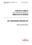
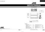
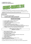
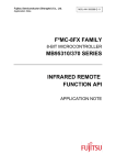
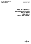
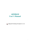
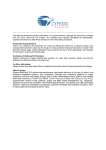
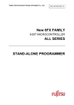
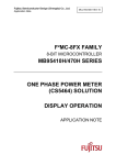
The following document contains information on Cypress products. Colophon The products described in this document are designed, developed and manufactured as contemplated for general use, including without limitation, ordinary industrial use, general office use, personal use, and household use, but are not designed, developed and manufactured as contemplated (1) for any use that includes fatal risks or dangers that, unless extremely high safety is secured, could have a serious effect to the public, and could lead directly to death, personal injury, severe physical damage or other loss (i.e., nuclear reaction control in nuclear facility, aircraft flight control, air traffic control, mass transport control, medical life support system, missile launch control in weapon system), or (2) for any use where chance of failure is intolerable (i.e., submersible repeater and artificial satellite). Please note that Spansion will not be liable to you and/or any third party for any claims or damages arising in connection with above-mentioned uses of the products. Any semiconductor devices have an inherent chance of failure. You must protect against injury, damage or loss from such failures by incorporating safety design measures into your facility and equipment such as redundancy, fire protection, and prevention of over-current levels and other abnormal operating conditions. If any products described in this document represent goods or technologies subject to certain restrictions on export under the Foreign Exchange and Foreign Trade Law of Japan, the US Export Administration Regulations or the applicable laws of any other country, the prior authorization by the respective government entity will be required for export of those products. Trademarks and Notice The contents of this document are subject to change without notice. This document may contain information on a Spansion product under development by Spansion. Spansion reserves the right to change or discontinue work on any product without notice. The information in this document is provided as is without warranty or guarantee of any kind as to its accuracy, completeness, operability, fitness for particular purpose, merchantability, non-infringement of third-party rights, or any other warranty, express, implied, or statutory. Spansion assumes no liability for any damages of any kind arising out of the use of the information in this document. ® ® ® TM Copyright © 2013 Spansion Inc. All rights reserved. Spansion , the Spansion logo, MirrorBit , MirrorBit Eclipse , TM ORNAND and combinations thereof, are trademarks and registered trademarks of Spansion LLC in the United States and other countries. Other names used are for informational purposes only and may be trademarks of their respective owners. Fujitsu Semiconductor (Shanghai) Co., Ltd. Application Note MCU-AN- 500064-E-10 F²MC-8FX FAMILY 8-BIT MICROCONTROLLER MB95310/370 SERIES LCD SOURCE CODE API APPLICATION NOTE LCD Source Code API V1.0 Revision History Revision History Date 2010-01-05 Author Jane Li Change of Records V1.0, First draft This manual contains 16 pages. 1. The products described in this manual and the specifications thereof may be changed without prior notice. To obtain up-to-date information and/or specifications, contact your Fujitsu sales representative or Fujitsu authorized dealer. 2. Fujitsu will not be liable for infringement of copyright, industrial property right, or other rights of a third party caused by the use of information or drawings described in this manual. 3. The contents of this manual may not be transferred or copied without the express permission of Fujitsu. 4. The products contained in this manual are not intended for use with equipments which require extremely high reliability such as aerospace equipments, undersea repeaters, nuclear control systems or medical equipments for life support. 5. Some of the products described in this manual may be strategic materials (or special technology) as defined by the Foreign Exchange and Foreign Trade Control Law. In such cases, the products or portions thereof must not be exported without permission as defined under the law. © 2009 Fujitsu Semiconductor (Shanghai) Co., Ltd MCU-AN- 500064-E-10 – Page 2 LCD Source Code API V1.0 CONTENTS CONTENTS REVISION HISTORY .............................................................................................................. 2 CONTENTS ............................................................................................................................ 3 1 INTRODUCTION ................................................................................................................ 4 2 MB95F310 LCD REGISTER .............................................................................................. 5 2.1 LCDCC (LCDC Control Register).............................................................................. 6 2.2 LCDCE1 (LCDC Enable Register 1) ......................................................................... 8 2.3 LCDCE2 to LCDCE6 (LCDC Enable Register 2 to 6) ............................................... 9 2.4 LCDCB1/LCDCB2 (LCDC Blinking Setting Register1/2) ........................................ 10 3 STEPS OF REALIZE LCD IN SOFTWARE ..................................................................... 11 4 LCD SAMPLE CODE....................................................................................................... 12 5 USAGE DEMO ................................................................................................................. 14 5.1 Register Use Attention ............................................................................................ 14 6 ADDITIONAL INFORMATION ......................................................................................... 15 7 APPENDIX ....................................................................................................................... 16 MCU-AN- 500064-E-10 – Page 3 LCD Source Code API V1.0 Chapter 1 Introduction 1 Introduction This document introduces API for LCD code. In MB95F310 MCU there is an LCD module which can drive LCD panel by SEG and COM pin. In following chapters we should describes the MB95F310 LCD register and code in C. MCU-AN- 500064-E-10 – Page 4 LCD Source Code API V1.0 Chapter 2 MB95F310 LCD register 2 MB95F310 LCD register This chapter describes MB95F310 LCD register. The LCD controller contains 20 bytes of display data memory and controls LCD display via 4 common outputs and 40 segment outputs. It offers a choice of three different duty outputs to directly drive the LCD panel. Figure 2-1 describes the recommended duty setting. Figure 2-1: Duty Setting MCU-AN- 500064-E-10 – Page 5 LCD Source Code API V1.0 Chapter 2 MB95F310 LCD register 2.1 LCDCC (LCDC Control Register) This register is used to set the clock, display mode, and power supply control. Figure 2-2 describes the register LCDCC. Figure 2-2: LCDCC Register Table 2-1 describes every bit of LCDCC. Register Table 2-1: LCDCC Register Description Description CSS Frame period generation clock select bit, when “0” is written, main clock is selected, or else sub clock is selected. LCDEN When “0” is set, LCD display is stopped; When “1” is set, LCD display continues even after transition to main stop or watch mode. VSEL Writing “0” will enable external resistor. Writing “1” will enable internal resistor. BK Writing “1” will enable display blanking. MS1 Selects LCD duty, refer to Table 2-2. MS0 Selects LCD duty, refer to Table 2-2. FP1 Frame period select bit, refer to Table 2-3. FP0 Frame period select bit, refer to Table 2-3. MCU-AN- 500064-E-10 – Page 6 LCD Source Code API V1.0 Chapter 2 MB95F310 LCD register Table 2-2 describes duty setting. MS1 Table 2-2: Duty Set Duty Description MS0 0 0 LCD operation halt 0 1 1/2 duty 1 0 1/3 duty 1 1 1/4 duty Table 2-3 describes frame period select. MS1 MS0 Table 2-3: Frame Period Set Duty Description Main Clock(SCC = 0) Main Clock(SCC = 1) 0 0 214 x N/FCH 26 x N/FCL 0 1 215 x N/FCH 27 x N/FCL 1 0 216 x N/FCH 28 x N/FCL 1 1 217 x N/FCH 29 x N/FCL MCU-AN- 500064-E-10 – Page 7 LCD Source Code API V1.0 Chapter 2 MB95F310 LCD register 2.2 LCDCE1 (LCDC Enable Register 1) This register is used to control port input, set the blink cycle, and enable LCD pins. Figure 2-3 describes register LCDCE1. Figure 2-3: LCDCE1 Register Table 2-4 describes every bit of LCDCE1. Register Table 2-4: LCDCE1 Register Description Description PICTL When “1” is written, SEG and COM work as SEG and COM at the same time it can also feedback high or low in just as I/O port input. BLSEL When blinking is enabled, writing “1” will select blinking interval to 1s, writing “0” will select blinking interval to 0.5s VE2 Writing “0” will enable V3 to be general I/O port. VE1 Writing “0” will enable V2 V1 V0 to be general I/O port. COM3 Writing “0” will enable COM3 to be general I/O port. COM2 Writing “0” will enable COM2 to be general I/O port. COM1 Writing “0” will enable COM1 to be general I/O port. COM0 Writing “0” will enable COM0 to be general I/O port. MCU-AN- 500064-E-10 – Page 8 LCD Source Code API V1.0 Chapter 2 MB95F310 LCD register 2.3 LCDCE2 to LCDCE6 (LCDC Enable Register 2 to 6) Those register are used to enable or disable SEG00 to SEG39 to be general I/O port. Figure 2-4 describes those register. Figure 2-4: LCDCE2 to LCDCE6 Register Table 2 – 5 lists how to control those registers. Table 2-5: LCDCE2 to LCDCE6 Register Description SEG00 to SEG39 Description 0 Work as general I/O port 1 Work as SEG port MCU-AN- 500064-E-10 – Page 9 LCD Source Code API V1.0 Chapter 2 MB95F310 LCD register 2.4 LCDCB1/LCDCB2 (LCDC Blinking Setting Register1/2) These two registers are used to enable or disable blinking on or off. Figure 2-5 describes these two registers. Figure 2-5: LCDCB1 and LCDCB2 Register Table 2-6 lists how to use those registers SnCm Table 2-6: LCDCB1 and LCDCB2 Register Description Description 0 Blink off 1 It means SEGnCOMm(SnCm) blink on MCU-AN- 500064-E-10 – Page 10 LCD Source Code API V1.0 Chapter 3 Steps of Realize LCD in Software 3 Steps of Realize LCD in Software This chapter describes steps of how to realize LCD. About LCD register they are divided to status register and control register. Following items will describe how to use these register to realize LCD function. Step one is initializing LCD. LCDCC register sets clock, voltage and duty LCDCE1 register sets V0~3 and COM work as LCD pin LCDCE2 to LCDCE6 registers set SEG work as LCD pin LCDCB1/LCDCB2 set blink status of SEG00 to SEG03 Step two is clearing LCD display. SEG00_01 to SEG30_31 registers write 0x0a to turn all LCDs off. Step three is display data user wanted. SEG00_01 to SEG30_31 registers write different data to display different value. MCU-AN- 500064-E-10 – Page 11 LCD Source Code API V1.0 Chapter 4 LCD Sample Code 4 LCD Sample Code This chapter describes MB95F310 LCD C code. Figure 4-1 describes the initial function. Figure 4-1: Initial Code Figure 4-2 lists the clear code. Figure 4-2: Clearing Code MCU-AN- 500064-E-10 – Page 12 LCD Source Code API V1.0 Chapter 4 LCD Sample Code Figure 4-3 lists the drive code. Figure 4-3: Drive Code MCU-AN- 500064-E-10 – Page 13 LCD Source Code API V1.0 Chapter 5 Usage Demo 5 Usage Demo This chapter describes something we must pay attention to when we use register to realize LCD. 5.1 Register Use Attention ¾ For the duty and bias selecting, the 1/4 duty working with 1/3 bias is recommended ¾ When selecting external voltage, please connect external circuit to V0~V3 MCU-AN- 500064-E-10 – Page 14 LCD Source Code API V1.0 Chapter 6 Additional Information 6 Additional Information For more information about how to use MB95310 EV-board, BGM Adaptor and SOFTUNE, please refer to EV-Board MB2146-450-E User Manual, or visit Websites: English version: http://www.fujitsu.com/cn/fsp/services/mcu/mb95/application_notes.html Simplified Chinese Version: http://www.fujitsu.com/cn/fss/services/mcu/mb95/application_notes.html MCU-AN- 500064-E-10 – Page 15 LCD Source Code API V1.0 Chapter 7 Appendix 7 Appendix Table 2-1: LCDCC Register Description .................................................................................. 6 Table 2-2: Duty Set .................................................................................................................. 7 Table 2-3: Frame Period Set .................................................................................................... 7 Table 2-4: LCDCE1 Register Description ................................................................................ 8 Table 2-5: LCDCE2 to LCDCE6 Register Description ............................................................. 9 Table 2-6: LCDCB1 and LCDCB2 Register Description ........................................................ 10 Figure 2-1: Duty Setting ........................................................................................................... 5 Figure 2-2: LCDCC Register .................................................................................................... 6 Figure 2-3: LCDCE1 Register .................................................................................................. 8 Figure 2-4: LCDCE2 to LCDCE6 Register ............................................................................... 9 Figure 2-5: LCDCB1 and LCDCB2 Register .......................................................................... 10 Figure 4-1: Initial Code ........................................................................................................... 12 Figure 4-2: Clearing Code ...................................................................................................... 12 Figure 4-3: Drive Code ........................................................................................................... 13 MCU-AN- 500064-E-10 – Page 16