1
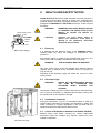
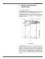
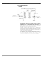
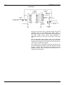
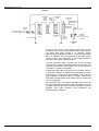
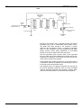
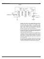
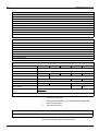
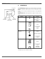
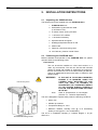
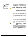
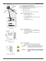
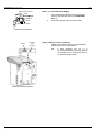
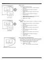
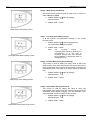
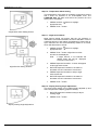
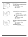
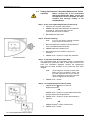
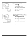
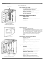
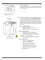
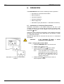
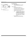
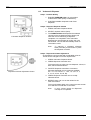
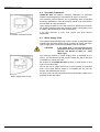
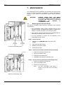
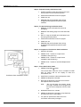
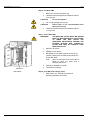
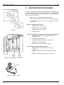
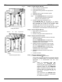
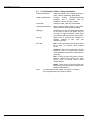
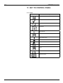
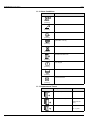
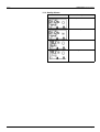
OPERATOR MANUAL
PURELAB Ultra
VERSION
VERSION 11 UK
UK –– 05/02
05/02
REF:
REF: MANU37248
MANU37248
ELGA
PURELAB Ultra Operator Manual
Copyright Note
ELGA® and PURELAB® are registered trademarks of Vivendi Water
Systems Ltd.
The information contained in this document is the property of ELGA
LabWater, a division of Vivendi Water Systems Ltd. and is supplied
without liability for errors or omissions.
No part of this document may be reproduced or used except as
authorized by contract or other written permission from Vivendi Water
Systems Ltd. The copyright and all restrictions on reproduction and
use apply to all media in which this information may be placed.
Vivendi Water Systems Ltd. pursue a policy of continual product
improvement and reserve the right to alter without notice the
specification, design, price or conditions of supply of any product or
service.
© Vivendi Water Systems Ltd. 2002
All rights reserved.
Publication ref: MANU37248
Version 1 - 05/02
ELGA is a trading name of Vivendi Water Systems and USFilter
(USA).
PURELAB Ultra Version 1 - 05/02
Page i
ELGA
PURELAB Ultra Operator Manual
TABLE OF CONTENTS
1.
2.
3.
INTRODUCTION ............................................................1
1.1
Product Range ......................................................1
1.2
Use of this Manual ................................................1
1.3
Customer Support .................................................1
HEALTH AND SAFETY NOTES....................................2
2.1
Electricity ...............................................................2
2.2
Ultraviolet Light .....................................................2
2.3
Sanitization Chemicals ..........................................2
2.4
Control of Substances Hazardous to Health
(COSHH) ...............................................................2
PRODUCT AND PROCESS DESCRIPTION .................3
3.1
Product Description ...............................................3
3.2
Process Description ..............................................4
3.3
Technical Specification .........................................9
4.
CONTROLS .................................................................12
5.
INSTALLATION INSTRUCTIONS ...............................13
6.
7.
5.1
Unpacking the PURELAB Ultra..........................13
5.2
Positioning the PURELAB Ultra .........................13
5.3
Connecting the PURELAB Ultra.........................15
5.4
Initial Controller Set-Up .......................................17
5.5
Setting Up Password / Resetting Replacement
Timers .................................................................22
5.6
Initial Start Up......................................................24
5.7
POU Filter Installation (LC134) - Optional
Accessory............................................................26
OPERATION ................................................................27
6.1
Intermittent or Continuous Recirculation .............27
6.2
Manual Dispense ................................................28
6.3
Volumetric Dispense ...........................................29
6.4
Automatic Calibration ..........................................30
6.5
Water Supply Flush .............................................30
MAINTENANCE ...........................................................31
7.1
Replacing the Purification Packs.........................31
7.2
Replacing the Ultra-Microfilter (LC109) ...............33
7.3
Replacing the Ultrafilter (LC151) .........................35
7.4
Replacing the Ultraviolet Lamp
(LC105 and LC118).............................................37
7.5
Replacing the Point-Of-Use Filter (LC134)..........38
7.6
Cleaning the Inlet Strainer (External) ..................39
TABLE OF CONTENTS - CONT'D
PURELAB Ultra Version 1 - 05/02
Page iii
PURELAB Ultra Operator Manual
ELGA
8.
SANITIZATION PROCEDURES.................................. 40
8.1
CT1 Sanitization Tablet - Safety Information ...... 42
9.
TROUBLE SHOOTING................................................ 43
10.
CONSUMABLES AND ACCESSORIES ..................... 44
11.
KEY TO CONTROL PANEL ........................................ 45
11.1 Icons ................................................................... 45
11.2 Alarm Conditions................................................. 46
11.3 Replacement Timers........................................... 46
11.4 Quality Alarms..................................................... 47
Page iv
12.
WARRANTY/CONDITIONS OF SALE ........................ 48
13.
USEFUL ADDRESSES ............................................... 50
PURELAB Ultra Version 1 - 05/02
ELGA
PURELAB Ultra Operator Manual
1. INTRODUCTION
1.1
Product Range
This operator manual has been prepared for the PURELAB Ultra
product models:
PURELAB Ultra Scientific
PURELAB Ultra Bioscience
PURELAB Ultra Genetic
PURELAB Ultra Ionic
PURELAB Ultra Analytic
1.2
PURELAB Ultra
Use of this Manual
This manual contains full details on installation, commissioning and
operation of the PURELAB Ultra unit. If the instructions in this
handbook are not followed then the performance of this product
and/or the safety of the user may be compromised.
1.3
Customer Support
Service support and consumable items are available from your local
supplier or distributor. Refer to customer service contact details
shown at the end of this publication.
PURELAB Ultra Version 1 - 05/02
Page 1
PURELAB Ultra Operator Manual
ELGA
2. HEALTH AND SAFETY NOTES
PURELAB Ultra products have been designed to be safe, however, it
is important that personnel working on these units understand any
potential dangers. All safety information detailed in this handbook is
highlighted as WARNING and CAUTION instructions. These are used
as follows:
WARNING!
WARNINGS ARE GIVEN WHERE FAILING
TO OBSERVE THE INSTRUCTION COULD
RESULT IN INJURY OR DEATH TO
PERSONS.
CAUTION!
Cautions are given where failure to
observe the instruction could result in
damage to the equipment, associated
equipment and processes.
Mains power socket
Fuse
ON/OFF
switch
Mains power lead
2.1
Mains Power Supply
Electricity
It is essential that the electrical supply to the PURELAB Ultra is
isolated before any items are changed or maintenance work
performed.
The ON/OFF switch is located at the left-hand side of the unit. The
mains power lead is located just behind the ON /OFF switch.
WARNING!
THIS APPLIANCE MUST BE EARTHED.
The main water supply should be isolated and residual pressure
released prior to removal of any Purification Packs or carrying out
work on the unit.
Switching off the electrical supply will isolate the source of mains
water pressure.
2.2
Ultraviolet Light
WARNING!
UNDER NO CIRCUMSTANCES SHOULD
THE LAMP BE CONNECTED AND
ACTIVATED
WHEN
OUTSIDE
THE
HOUSING.
The Genetic, Analytic and Ionic units are fitted with an ultraviolet lamp.
The UV lamp is enclosed in a stainless steel chamber ensuring that
the operator will not be exposed to UV light.
2.3
Sanitization Chemicals
During the sanitization cycle a CT1 sanitization tablet is used and
relevant safety information is included in this handbook. A safety data
sheet conforming to COSHH regulations is also provided with the
tablets and should be read before a tablet is used.
2.4
UV Lamp
Control of Substances Hazardous to Health (COSHH)
Material safety data sheets covering the various replaceable
Purification Packs are available upon request. Contact your local
supplier or distributor.
Ultra with UV Lamp
Page 2
PURELAB Ultra Version 1 - 05/02
ELGA
PURELAB Ultra Operator Manual
3. PRODUCT AND PROCESS
DESCRIPTION
3.1
Product Description
The PURELAB Ultra water purification unit has been specifically
designed to provide a supply of ultrapure water with very low levels
of impurities for laboratory, medical and industrial applications.
The PURELAB Ultra can be bench, underbench or wall mounted with
an optional wall mounting kit. A range of accessories is available to
complement the unit (see Section 10. - Consumables and
Accessories, for detail).
Control Panel
Dispense Nozzle
Dispense Controller
Door
PURELAB Ultra
The PURELAB Ultra range of water purification units has been
designed to provide the ultimate in high purity water for laboratory
applications. The products need to be fed with pre-treated water,
typically from a reverse osmosis supply. They can be operated directly
from a ringmain feed as point of use polishers, with or without local
buffer storage, using a Docking Vessel or suitable reservoir.
Alternatively, they can be supplied from a local pre-treatment/storage
system, for example a PURELAB Prima and Docking Vessel
combination.
PURELAB Ultra Version 1 - 05/02
Page 3
PURELAB Ultra Operator Manual
ELGA
3.2
Process Description
Scientific
Intermediate
Water
Quality Sensor
Temperature
Sensor
Outlet Water
Quality Sensor
NRV
Solenoid Valve
Solenoid
Valve
Feedwater Inlet
(Pre-purified Water)
Flow
Sensor
Dispense Controller
Pump
Solenoid Valve
Primary
Purification
Pack
Polishing
Purification
Pack
0.2µm Point-of-use Filter
(Optional)
Purified Water
Outlet
Drain
Pre-treated water enters via an inlet solenoid, passes
through a flow sensor and is pumped through the primary
purification pack, an intermediate water quality sensor, a
polishing purification pack and final temperature and water
quality sensors before being dispensed or recirculated
through a non-return valve back to the pump inlet.
The first purification pack removes most of the impurities
from the water and the intermediate water quality sensor then
measures the resistivity of the water from the first pack to
check when it needs to be replaced.
Any remaining ionic and organic impurities are removed by
the second polishing purification pack. Product water
resistivity and temperature are measured before dispense.
Page 4
PURELAB Ultra Version 1 - 05/02
ELGA
PURELAB Ultra Operator Manual
Bioscience
Intermediate
Water
Quality Sensor
Temperature
Sensor
Outlet Water
Quality Sensor
NRV
Ultrafiltration
Membrane
Solenoid
Valve
Feedwater Inlet
(Pre-purified Water)
Flow
Sensor
Pump
Solenoid Valve
Primary
Purification
Pack
Dispense Controller
Polishing
Purification
Pack
Drain
Solenoid Valve
Flush
Solenoid
Valve
Drain
0.2µm Point-of-use Filter
(Optional)
Purified Water
Outlet
Pre-treated water enters via an inlet solenoid, passes
through a flow sensor and is pumped through the primary
purification pack, an intermediate water quality sensor, a
polishing purification pack, an ultrafilter and final temperature
and water quality sensors before being dispensed or
recirculated through a non-return valve back to the pump
inlet.
The first purification pack removes most of the impurities
from the water and the intermediate water quality sensor then
measures the resistivity of the water from the first pack to
check when it needs to be replaced.
Any remaining ionic and organic impurities are removed by
the second polishing purification pack; the ultrafilter removes
pyrogens, bacteria and other microbial impurities as well as
particles. Product water resistivity and temperature are
measured before dispense.
PURELAB Ultra Version 1 - 05/02
Page 5
PURELAB Ultra Operator Manual
ELGA
Genetic
Intermediate
Temperature
Post UV
Water
Sensor
Quality
Quality
Sensor
Sensor
Temperature
Sensor
Outlet Water
Quality Sensor
NRV
Ultrafiltration
Membrane
Solenoid
Valve
Feedwater Inlet
(Pre-purified Water)
Flow
Sensor
Pump
Solenoid Valve
Primary
Purification
Pack
UV Lamp
Polishing
Purification
Pack
Drain
Flush
Solenoid
Valve
Drain
Solenoid Valve
Dispense
Controller
0.2µm Point-of-use Filter
(Optional)
Purified Water
Outlet
Pre-treated water enters via an inlet solenoid, passes
through a flow sensor and is pumped through the primary
purification pack and an intermediate water quality sensor.
The water then flows through a UV chamber, further
resistivity and temperature sensors, a polishing purification
pack, an ultrafilter and final temperature and water quality
sensors before being dispensed or recirculated through a
non-return valve back to the pump inlet.
The first purification pack removes most of the impurities
from the water and the intermediate water quality sensor then
measures the resistivity of the water from the first pack to
check when it needs to be replaced.
Purified water flows directly through the UV chamber where it
is exposed to intense UV radiation at wavelengths of 254nm
and 185nm to provide continuous bacterial control and the
photo-oxidation of residual organic impurities. The second
temperature compensated water quality sensor provides data
for TOC monitoring.
Any remaining ionic and organic impurities are removed by
the second polishing purification pack; the ultrafilter removes
pyrogens, bacteria and other microbial impurities as well as
particles. Final water resistivity and temperature are
measured before dispense.
Page 6
PURELAB Ultra Version 1 - 05/02
ELGA
PURELAB Ultra Operator Manual
Ionic
Temperature
Sensor
Intermediate
Water Quality
Sensor
Outlet Water
Quality
Sensor
NRV
Solenoid
Valve
Feedwater Inlet
(Pre-purified Water)
Flow
Sensor
UMF
Pump
Solenoid Valve
Primary
Purification
Pack
UV Lamp
Polishing
Purification
Pack
Solenoid Valve
Dispense Controller
0.2µm Point-of-use Filter
(Optional)
Purified Water
Outlet
Drain
Pre-treated water enters via an inlet solenoid, passes
through a flow sensor and is pumped through the primary
purification pack and an intermediate water quality sensor.
The water then flows through a UV chamber, a further
resistivity and temperature sensor, a polishing purification
pack, an ultra microfilter and final temperature and water
quality sensors before being dispensed or recirculated
through a non-return valve back to the pump inlet.
The first purification pack removes most of the impurities
from the water and the intermediate water quality sensor then
measures the resistivity of the water from the first pack to
check when it needs to be replaced.
Purified water flows directly through the UV chamber where it
is exposed to intense UV radiation at a wavelength of 254nm
to provide continuous bacterial control.
Any remaining ionic and organic impurities are removed by
the second polishing purification pack; the ultra microfilter
removes bacterial impurities and particles. Product water
resistivity and temperature are measured before dispense.
PURELAB Ultra Version 1 - 05/02
Page 7
PURELAB Ultra Operator Manual
ELGA
Analytic
Intermediate
Temperature
Water
Post UV
Sensor
Quality
Quality
Sensor
Sensor
Temperature
Sensor
Outlet Water
Quality
Sensor
NRV
Solenoid
Valve
Feedwater Inlet
(Pre-purified Water)
Flow
Sensor
UMF
Pump
Solenoid Valve
Primary
Purification
Pack
UV Lamp
Polishing
Purification
Pack
Solenoid Valve
Dispense Controller
0.2µm Point-of-use Filter
(Optional)
Purified Water
Outlet
Drain
Pre-treated water enters via an inlet solenoid, passes
through a flow sensor and is pumped through the primary
purification pack and an intermediate water quality sensor.
The water then flows through a UV chamber, further
resistivity and temperature sensors, a polishing purification
pack, an ultra microfilter and final temperature and water
quality sensors before being dispensed or recirculated
through a non-return valve back to the pump inlet.
The first purification pack removes most of the impurities
from the water and the intermediate water quality sensor then
measures the resistivity of the water from the first pack to
check when it needs to be replaced.
Purified water flows directly through the UV chamber where it
is exposed to intense UV radiation at wavelengths of 254nm
and 185nm to provide continuous bacterial control and the
photo-oxidation of residual organic impurities. The second
temperature compensated water quality sensor provides data
for TOC monitoring.
Any remaining ionic and organic impurities are removed by
the second polishing purification pack; the ultra microfilter
removes bacterial impurities and particles. Product water
resistivity and temperature are measured before dispense.
Page 8
PURELAB Ultra Version 1 - 05/02
ELGA
PURELAB Ultra Operator Manual
3.3
Technical Specification
The Technical Specifications for the PURELAB Ultra are as follows:
Feedwater*
Parameter
Limits
Source - Originally from potable supply, then
pre-treated
Preferably reverse osmosis (RO) or filtered service deionisation (SDI) or distilled.
Fouling Index (max)
1 for all models. A 0.2 micron membrane prefilter is recommended for all non-RO feeds.
Service Deionisation (SDI) - MΩ-cm
1 MΩ-cm minimum resistivity at exhaustion.
Reverse Osmosis (RO) - µS/cm
Ideally < 30 µS/cm
Free Chlorine
0.05ppm max.
TOC
50ppb max.
Carbon Dioxide
30ppm max.
Silica
2ppm max.
Particulates
Filtration down to 0.2 micron advisable to protect internal and/or point of use filters
Temperature
1-40°C - Recommended 10-15°C
Flowrate (maximum requirement)
130 l/hr
Drain requirements (gravity fall with air gap).
Maximum during service
Up to 2 l/min
Feedwater Pressure
0.7bar (10psi), maximum, 0.07bar (1psi) minimum
Note: mixed bed or twin bed deionised supplies should be cation limited at exhaustion.
* Contact technical support for advice on feedwaters outside the range listed.
Note:
Different system configurations are available for different feedwater sources. See system set
up.
Dimensions
Height
490mm (19.3")
Width
410mm (16.2")
Depth
365mm (14.4")
Weight
Scientific
14.0kg (30.8 lb.)
Bioscience
14.5kg (32.0 lb.)
Ionic
14.5kg (32.0lb.)
Analytic
15.0kg (33.1lb.)
Genetic
15.0kg (33.1lb.)
Connections
Inlet-quick connect
8mm (5/16") OD
Drain
8mm (5/16") OD
Flush - Bioscience/ Genetic
8mm (5/16") OD
Positioning
Wall, bench or under bench mounted.
Environment
Clean dry indoor. Temp 5-40°C.
Humidity max 80% non-condensing.
PURELAB Ultra Version 1 - 05/02
Page 9
PURELAB Ultra Operator Manual
ELGA
Electrical Requirements
Mains input
100 -240V ac, 50-60Hz all models
System voltage
24V dc
Power consumption during recirculation
60VA
Power consumption during dispense
75VA
Fuses
2 x T6.3 Amp
Reservoir level connection
Jack Plug 3.5mm
Noise level during recirculation
<40dBA
User Interface
Display
Continuous graphical quality display
Graphical flow schematic on screen with mimic display
Backlit display with Intuitive Icons
Adjustable settings
Indicators
Alarms-Audiovisual
Outputs
Volumetric dispense
Selectable dispense volumes (0.1 – 60.0 liters)
Recirculation mode
Intermittent or continuous
Feed water type
Selectable (RO/DI/SDI)
Display viewing angle
Adjustable electronically
Water quality units
Selectable (MΩ-cm or µS/cm)
Water quality alarm
Selectable alarm setpoints
Date / time
Adjustable
Auto restart after power failure
Selectable (On/Off)
Audible alarm
Selectable (On/Off)
Temperature control
Selectable alarm setpoints
Night service
Selectable (On/Off)
Product water quality
Resistivity or conductivity
Intermediate water quality
Resistivity or conductivity
Temperature
Degrees Centigrade or Fahrenheit
Total Organic Carbon (TOC)*
ppb C
Purification pack
Replacement date
UV lamp*
Replacement date
Filter*
Replacement date
Purified water purity
Above set point alarm
Temperature****
Above set point alarm
UV lamp operation*
Imminent lamp failure or failure to start
Calibration
Calibration alarm – calibration required
Purification pack
Change reminder
UV lamp*
Change reminder
Filter*
Change reminder
Reservoir****
Low level / level control disconnect alarm
RS232 printer connection
RS232 remote display connection
Volt free contact-internal
Remote dispense
Page 10
PURELAB Ultra Version 1 - 05/02
ELGA
PURELAB Ultra Operator Manual
Safety Features
Power fail safe
Water temperature alarm
Water quality alarm
Purification pack interlock
UV current monitoring
Timeout of manual dispense
Low operating voltage 24V
Dry contact alarm connection
Visual alarms
Audible alarms
Operational Features
Low noise levels – minimum intrusion
Continuous calibration to traceable standards
Drop dispense
Multistage monitoring
Restart on power interrupt
Volumetric dispense
Optional printer kit for record of operating parameters
Optional remote display
Purified Water Specification
Scientific
Ionic
Flowrate
2.0 l/min max.
Inorganic
Resistivity 18.2 MΩ-cm (0.055µs/cm)
TOC
**<15ppb
**<5ppb
Bacteria
***<1cfu/ml
<1cfu/ml
Pyrogens
-
pH
Effectively neutral
Particles
***0.2µm
RNase / DNase
-
Capacity
56,000 liters
(LC147)
µS/cm at pH7.0
Analytic
**<2ppb
0.05µm
Bioscience
Genetic
**<10ppb
**<3ppb
<0.03Eu/ml
<0.001Eu/ml
Ultrafiltration
Free
>18MΩ-cm per single purification pack
Conforms to ASTM, CAP, NCCLS – TYPE 1 and BS3978 Grade 1 Specification.
*
On some models only.
**
Dependant on feedwater - recommended feed <50ppb TOC
***
****
With POU filter fitted.
Switches process off.
Purification Packs
Standard pack LC147 recommended for most applications. Refer to Section 10 for alternative cartridges.
As part of our policy of continual improvement we reserve the right to
alter the specifications given in this document.
PURELAB Ultra Version 1 - 05/02
Page 11
PURELAB Ultra Operator Manual
ELGA
4. CONTROLS
Process button
The PURELAB Ultra operates with a tactile membrane control panel,
which has a graphics display window and four multi-purpose control
buttons.
Details of how to use the controls will be given in the appropriate
sections.
The PURELAB Ultra control panel has a range of control icons as
follows:
Button
Icon
PROCESS
Left hand
Control button
Centre
Control button
Function
Turns the process
on/off
Right hand
Control button
ESCAPE from any
feature
Control Panel
LEFT
Menu
Scroll
(0.10)*
Preset dispense
volume
Reset
CENTRE
Accept
Volumetric dispense
(0.50)*
RIGHT
Preset dispense
volume
Mute Alarm
Printer
(1.00)*
Preset dispense
volume
Intermittent
recirculation
* Example only - Ref. to Section 6.3 Step 3.
Page 12
PURELAB Ultra Version 1 - 05/02
ELGA
PURELAB Ultra Operator Manual
5. INSTALLATION INSTRUCTIONS
5.1
Unpacking the PURELAB Ultra
The following items are supplied with your PURELAB Ultra.
1. PURELAB Ultra unit.
2. Sanitization by-pass blocks LA638
(2 off, fitted in unit).
3. 6 metres of 8mm (5/16") O/D tube.
4. 1 off Pack of CT1 tablets.
5. 1 off Strainer Assembly.
6. Operator Manual in English.
7. Multilingual Operator Manual on CD.
8. Mains Lead.
9. Reservoir Level Connecting Lead.
10. Icon Directory, fitted on inside of door.
5.2
Positioning the PURELAB Ultra
Before installation and operation of the PURELAB Ultra unit, please
read and observe the following points.
Environment
The unit should be installed on a flat, level surface, in a
clean, dry environment. The unit can also be wall mounted
against a vertical wall capable of supporting the weight (for
this we recommend the use of the wall mounting kit Part No.
LA610 on substantial brick/concrete walls or LA622 for stud
partition walls).
WARNING!
Rear Mounting Points
Note:
IF THE UNIT IS TO BE WALL MOUNTED,
ENSURE IT IS MOUNTED USING THE
CORRECT WALL MOUNTING KIT AND
THAT THE WALL IS CAPABLE OF
SUPPORTING THE OPERATING WEIGHT
OF THE SYSTEM. ALWAYS CAREFULLY
FOLLOW THE INSTRUCTIONS INCLUDED
IN THE KIT.
Refer to Specifications for unit weights
(Section 3.4 - Technical Specification).
The unit is designed to operate safely under the following conditions:
• Indoor Use
• Altitude up to 2000m
• Temperature Range 5 - 40°C
• Maximum Relative Humidity 80% @ 31°C decreasing
linearly to 50% @ 40°C, non-condensating
The unit is in Installation Category II, Pollution Degree 2, as per
IEC1010-1.
Unit Rear Mounting Points
PURELAB Ultra Version 1 - 05/02
Page 13
PURELAB Ultra Operator Manual
ELGA
Mains power socket
Fuse
ON/OFF
switch
Mains power lead
Electrical
The units can be connected universally to any electrical
supply in the range of 100 - 240V and 50 - 60Hz. The mains
lead is supplied with a molded plug on one end and a molded
connector to the unit on the other. The unit should be
connected to an earth. The unit includes a battery which will
require changing on a periodic basis, typically every 3-5
years. (Contact local Service provider)
WARNING!
Electrical Connections
DANGER OF EXPLOSION IF BATTERY IS
INCORRECTLY REPLACED. REPLACE
ONLY WITH THE SAME OR EQUIVALENT
TYPE
RECOMMENDED
BY
THE
MANUFACTURER (3 VOLTS, LITHIUM
CR2032). DISPOSE OF USED BATTERIES
ACCORDING TO THE MANUFACTURER’S
INSTRUCTIONS.
Drain/Flush
A semi-rigid flexible connection to a sink or suitable drain
capable of at least 2.0l/min is required. The drain point
should have a gravity fall below the level of the unit and any
connections direct to drain should have an air-break device
fitted. On the Genetic & Bioscience units a separate flush line
to drain is required. The drain and flush drain lines should run
individually to a convenient drain point.
Feed Water
The feedwater should be potable water, pre-purified using
reverse osmosis, deionisation, or distillation. If using a supply
other than reverse osmosis treated, it is strongly
recommended that a 0.2 micron membrane filter is installed
prior to remove colloidal impurities. The feedwater should
enter the PURELAB Ultra via an 8mm (5/16") O/D semi rigid
tube, and should be in the temperature range 1 to 40°C (34
to 104°F). To ensure optimum performance it is
recommended that the feedwater temperature be between 10
to 15°C.
CAUTION!
Operating with feed water temperatures
outside the range from 1 to 40°C (33.8 to
104°F) will cause damage to the PURELAB
Ultra unit.
For pressurized feeds, the minimum direct inlet pressure is
0.07bar (1.0psi) and maximum inlet pressure is 0.7bar
(10psi). Higher feedwater pressures must be reduced using a
pressure regulator valve (Part No. LA575).
Reservoir feeds to the PURELAB Ultra unit should be
positioned at the same height, or above the unit, to provide a
positive flooded inlet pressure of approximately 0.07bar
(1psi).
Page 14
PURELAB Ultra Version 1 - 05/02
ELGA
PURELAB Ultra Operator Manual
Connector
Collet
Blanking
transit plug
5.3
Connecting the PURELAB Ultra
Once the PURELAB Ultra unit has been positioned either on a wall or
on a bench, it should be connected as follows:
• Mains water inlet tube
Pull plug
• Drain tube - to drain
• Flush tube (Bioscience and Genetic) - to drain
Depress
collet
Clean square
cut end
Tube 8mm OD
Step 1 - Remove Transit Plugs
1. PUSH in collet on connector.
2. PULL out transit plug.
3. CUT a clean square end on an 8mm OD semi
rigid drain tube.
4. PUSH tube into connector.
Simply push in tube to attach
Tube in secured position
Fitting tubes
Step 2 - Connect Water Inlet
1. Connect 8mm tube from the PURELAB Ultra
inlet to the inlet strainer.
Direction of
water flow
2. Connect the inlet strainer to the pre-purified
water supply.
Collar
Mesh filter
Collar
Strainer
Inlet
Feed Water Inlet
Step 3 - Connect Drains
1. Connect 8mm tube from the drain and UF drain
(if fitted) and direct to a suitable drainage point.
UF Drain
CAUTION!
The drain and flush lines should allow a
gravity fall to drain with no restrictions.
CAUTION!
If the water supply is at a pressure greater
than 0.7bar (10psi) fit a pressure regulator
(LA575).
Drain
Inlet
Inlet and Drain Connection
PURELAB Ultra Version 1 - 05/02
Page 15
PURELAB Ultra Operator Manual
ELGA
Mains power socket
Fuse
ON/OFF
switch
Step 4 - Connect Electrical Supply
1. PLUG mains power lead into the mains power
socket on the left hand side of the PURELAB
Ultra unit.
2. PLUG mains power lead into mains socket.
Mains power lead
Electrical Connections
RS232
Reservoir
level
connection
Step 5 - Resevoir Level Connection
1. INSERT jack plugs into the level control socket
located at rear of unit and reservoir.
Note:
Level
control
If wall mounting the unit it is
recommended that the jack plug should
be inserted prior to locating the unit on
the wall mounting bracket.
Reservoir Level Connection
Page 16
PURELAB Ultra Version 1 - 05/02
ELGA
PURELAB Ultra Operator Manual
Process button
5.4
Initial Controller Set-Up
The PURELAB Ultra control panel is fitted with four control buttons.
These are:
button, which switches the
1. The PROCESS
purification process ON and OFF.
2. Three software controlled touch pad buttons
which are used to control set-up and process
control functions.
When the PURELAB Ultra unit is started for the first time after
installation the following steps should be carried out to set up system
preferences:
Left hand
Control button
Centre
Control button
Right hand
Control button
Control Panel
Step 1 - Setting Up Menu Options
1. SWITCH the mains power on to initialize the
controller hardware set-up sequence.
Note:
Always allow the initialization process
to complete. With the by-pass blocks in
place press the PROCESS button to
return to the initial power up screen.
button to go to the next screen
2. PRESS MENU
to activate the set up menu sequence.
A series of set-up screens will now be displayed.
Various control icons are used to allow you to step
through the set-up instruction process. These icons
include:
Start Up Screen
•
A “scroll” icon indicated by an arrow
•
An “accept” icon indicated by a tick 9
•
A “selection” icon indicated by a At any stage during the Controller Set-up the
PROCESS button can be pressed to escape back to
the initial power up screen.
Step 2 - Password
Restricts access to set up menu sequence.
1. ROTATE Dispense Controller to enter password
code. The default password code is 000.
2. PRESS TICK 9 button.
Note:
To reset password refer to Section 5.5.
Password Screen
PURELAB Ultra Version 1 - 05/02
Page 17
PURELAB Ultra Operator Manual
ELGA
Step 3 - Clock
Set to display the current local time.
1. PRESS Dispense Controller. A cursor will appear
under hour.
2. ROTATE Dispense Controller to increase or
decrease hour.
3. PRESS Dispense Controller to step cursor onto
minute.
4. ROTATE Dispense Controller to increase or
decrease minute.
5. PRESS Dispense Controller to accept the minute
setting and set the seconds to 00.
Clock Screens
6. PRESS TICK 9 button.
Step 4 - Date
Used to instigate change reminders, it will appear on printed
records.
1. PRESS Dispense Controller. A cursor will appear
under day.
2. ROTATE Dispense Controller to increase or
decrease day.
3. PRESS Dispense Controller to step cursor onto
month.
Date Screen
4. ROTATE Dispense Controller to increase or
decrease month.
5. PRESS Dispense Controller to step cursor onto
year.
6. ROTATE Dispense Controller to increase or
decrease year.
7. PRESS TICK 9 button.
Step 5 - Audible Alarm Enabled/Disabled
This display provides the option of either enabling the audible
alarm, causing it to sound (whilst the alarm icon flashes) or
disabling the audible alarm causing it to remain muted.
1. PRESS SCROLL
button to highlight box.
2. PRESS TICK 9 button.
Note:
The visual alarm cannot be disabled.
Audible Alarm Enable/Disable Screen
Page 18
PURELAB Ultra Version 1 - 05/02
ELGA
PURELAB Ultra Operator Manual
Step 6 - Water Purity Unit Setting
This screen allows preferred units of water purity to be set, to
either, MΩ.cm or µS/cm.
1. PRESS SCROLL
appropriate box.
button to highlight
2. PRESS TICK 9 button.
Water Purity Unit Setting Screen
Step 7 - Uncompensated Water Quality
A U will indicate uncompensated readings in the normal
process screen.
button to highlight box if
1. PRESS SCROLL
uncompensated reading is required.
2. PRESS TICK 9 button.
Note:
Uncompensated Water Quality Screen
The
on-going
display
of
uncompensated values is generally not
recommended as it can lead to
confusion among users and increase
the possibilities of dispensing water of
inadequate purity.
Step 8 - Product Water Purity Alarm Settings
This screen is used for setting the purity value at which the
product water purity alarm will activate. The unit will alarm if this
level is passed but will not switch off the process. The alarm will
automatically clear if the water purity returns above its specified
limit.
1. PRESS SCROLL
appropriate box.
button to highlight
2. PRESS TICK 9 button.
Outlet Purity Alarm Setting Screen
Step 9 - Intermediate Purity Alarm Point
This screen is used for setting the value at which the
intermediate water purity alarm will activate indicating that the
purification packs require changing. The unit will alarm if this
value is passed but will not switch off the process.
1. PRESS SCROLL
appropriate box.
button to highlight
2. PRESS TICK 9 button.
Intermediate Purity Alarm Point Screen
PURELAB Ultra Version 1 - 05/02
Page 19
PURELAB Ultra Operator Manual
ELGA
Step 10 - Temperature Alarm Setting
The temperature of the water is constantly monitored to ensure
that it does not increase to an unacceptable level. The
PURELAB Ultra will alarm and switch the process off if the
alarm point is exceeded.
1. PRESS SCROLL
appropriate box.
button to highlight
2. PRESS TICK 9 button.
Temperature Alarm Setting Screen
Step 11 - Night Service Mode
Night Service Mode will ensure that the unit performs in
intermittent recirculation between the hours selected in order to
maximize efficiency and reduce the likelihood of heat build up.
Upon selection the unit will automatically default to a screen,
which will allow times to be set.
1. PRESS SCROLL
appropriate box.
button to highlight
2. PRESS TICK 9 button. Night Service times
should now be displayed.
Note:
If Night Service is not selected the
default times will still be displayed.
Proceed to instruction 7.
3. PRESS Dispense Controller. A cursor will appear
under night service start.
Night Service Setting Screens
4. ROTATE Dispense Controller to increase or
decrease time in increments of 30 minutes.
5. PRESS Dispense Controller to step to night
service time end.
6. ROTATE Dispense Controller to increase or
decrease time in increments of 30 minutes.
7. PRESS TICK 9 button.
Step 12 - Display Viewing Angle Adjustment
The angle of the display can be electronically adjusted up and
down to optimize the display graphics visibility.
1. ROTATE Dispense Controller slowly to adjust
viewing angle.
2. PRESS TICK 9 button.
Display Viewing Angle Adjustment
Page 20
PURELAB Ultra Version 1 - 05/02
ELGA
PURELAB Ultra Operator Manual
Step 13 - Auto-Restart
This allows the selection of the AUTO/MANUAL restart option.
If auto restart is selected the unit will automatically restart after
a temporary loss of power to the unit. In manual mode the unit
will remain in standby mode.
1. PRESS SCROLL
appropriate box.
button to highlight
2. PRESS TICK 9 button.
Auto-Restart Screen
Step 14 - Water Feed Type
To ensure maximum efficiency the process is tailored for feed
waters with different pretreatment.
Water Feed Type Screen
RO
Ideally <30µS/cm and supplied from either an RO
(permeate) loop or reservoir.
DI
Filtered DI loop or reservoir with recirculation
maintaining a quality >1MΩ-cm.
SDI
Service Deionisation with 0.2 micron prefilter feed
directly into the unit via a pressure regulator
(LA575).
1. PRESS SCROLL
appropriate box.
button to highlight
2. PRESS TICK 9 button.
Step 15 - Reservoir Level (only shown if RO feed is selected)
When operating the system from a reservoir it is recommended
that a low-level switch be connected to protect the system from
running dry.
1. PRESS SCROLL
appropriate box.
button to highlight
2. PRESS TICK 9 button.
The Controller Set-up is now complete.
Reservoir Level Screen
Note:
To escape from any of the set-up
screens press the PROCESS button.
PURELAB Ultra Version 1 - 05/02
Page 21
PURELAB Ultra Operator Manual
ELGA
5.5
Setting Up Password / Resetting Replacement Timers
CAUTION!
Before resetting any of the Consumable
Replacement/Reminder Dates, ensure that
the appropriate new Consumable has been
installed and correctly located in the
PURELAB Ultra.
Step 1 - Enter Consumable Replacement Timer Set-up
1. SWITCH OFF at power inlet module.
2. PRESS and HOLD left hand button and SWITCH
unit back on. The unit will now enter the
Consumable Timer set up display.
3. RELEASE left hand button.
Step 2 - Password Change
Note:
If you do not wish to change password
then proceed to instruction 4.
1. ROTATE Dispense Controller to enter password
code. The default password is 000.
2. PRESS Dispense Controller once.
3. ROTATE Dispense Controller to enter new
password.
4. PRESS TICK 9 button to accept new password.
Password Screen
Step 3 - Purification Pack Replacement Date
The replacement date for Purification Packs is automatically
calculated from information held on data tags secured to the
pack. The information displayed confirms the replacement
dates and the serial numbers of the packs that have been
installed.
Note:
At this stage the unit will not have been
fitted with any Purification Packs and
the date displayed will not be relevant.
Upon installation of the packs this date
will be changed and reconfirmed.
1. PRESS TICK 9 button.
Step 4 - UV Lamp Replacement Date (if fitted)
1. PRESS RESET
button to reset UV
Replacement Date
OR
PRESS TICK 9 button to accept Replacement Date
and proceed to Filter Replacement.
2. PRESS TICK 9 button to confirm that resetting is
required
OR
PRESS CROSS χ button to abort reset.
3. PRESS TICK 9 button.
UV Lamp Replacement Date Screens
Page 22
PURELAB Ultra Version 1 - 05/02
ELGA
PURELAB Ultra Operator Manual
Step 5 - Filter Replacement Date (if fitted)
1. PRESS RESET
button to reset the Filter
Replacement Date
OR
PRESS TICK 9 button to accept Replacement Date
and proceed to Sanitization Reminder.
2. PRESS TICK 9 button to confirm that resetting is
required
OR
PRESS CROSS χ button to abort reset.
3. PRESS TICK 9button.
Filter Replacement Date Screens
Step 6 - Sanitization Reminder Reset
The Sanitization Reminder will appear at the end of the
Sanitization routine and can be either reset for a monthly
reminder or switched off.
1. PRESS RESET
Reminder Date
button to reset Sanitization
OR
PRESS TICK 9 button to accept Reminder Date
OR
PRESS CROSS χ button to clear the Reminder Date –
Proceed to Instruction 3 to confirm.
Sanitization Reminder Reset Screens
2. PRESS TICK 9 button to confirm that resetting is
required
OR
PRESS CROSS χ button to abort reset.
3. PRESS TICK 9 button.
PURELAB Ultra Version 1 - 05/02
Page 23
PURELAB Ultra Operator Manual
ELGA
5.6
By-pass blocks
Initial Start Up
Step 1 - Prepare Water Supply
1. The PURELAB Ultra should be installed
correctly as described in Section 5.3.
2. TURN ON the feedwater supply to the unit and
adjust the inlet pressure.
3. CHECK all tube connections are watertight and
that there are no leaks.
Step 2 - Prepare Sanitization By-pass Blocks
1. OPEN front door.
2. CHECK by-pass blocks are correctly located and
locked in place.
3. CLOSE door.
By-pass block hangers
Location of By-pass Blocks
Step 3 - Initial Rinse
1. SWITCH ON electrical supply.
The PURELAB Ultra will automatically go into a rinse
procedure (36 mins) to rinse bacteriostatic agents from
the unit. This rinse must be completed; the process
function will be inhibited until the rinse is complete.
2. Upon completion of the rinse the unit will bleep
twice.
Step 4 - Remove Sanitization By-pass Blocks
1. SWITCH OFF power.
Initial Rinse Screen
2. OPEN the door.
3. REMOVE both by-pass blocks and pour contents
away.
4. STORE by-pass blocks on hangers inside the
door.
Step 5 - Fit Primary Purification Pack
1. REMOVE a new Purification Pack from its
packaging.
2. REMOVE the sealing plugs from inlet and outlet
ports.
3. WET ‘O’ rings and SLIDE new Purification Pack
into the left hand position pushing upwards
against pack reader contacts.
Primary
purification
pack
Polishing
purification
pack
Location of Purification Packs
Page 24
4. POSITION Purification Pack onto spigots.
5. PUSH into unit.
6. ENSURE that the Purification Pack is fully
engaged and dropped down past the retainers.
PURELAB Ultra Version 1 - 05/02
ELGA
PURELAB Ultra Operator Manual
Retainer
Spigots
Step 6 - Fit Polishing Purification Pack
1. REMOVE a new Purification Pack from its
packaging.
2. REMOVE the sealing plugs from inlet and outlet
ports.
3. WET ‘O’ rings and SLIDE new Purification Pack
into the right hand position pushing upwards
against pack reader contacts.
4. POSITION Purification Pack onto spigots.
5. PUSH into unit.
6. ENSURE that the Purification Pack is fully
engaged and dropped down past the retainers.
Fit Purification Pack
Step 7 - Acceptance of Purification Pack Installation
1. SWITCH ON power.
2. PRESS TICK 9 button to initiate programming of
Polishing Pack.
3. PRESS TICK 9 button to accept Polishing Pack
Installation date.
4. PRESS TICK 9 button to initiate programming of
Primary Pack.
5. PRESS TICK 9 button to accept Primary Pack
Installation date.
6. PRESS TICK 9 button to calculate Replacement
date.
Purification Pack Installation Screens
Step 8 - Purification Pack Rinse
1. PRESS PROCESS
button. ALLOW calibration
routine to be completed and process screen to
appear.
2. PRESS Dispense Controller. DIRECT dispense
flow to drain or collect in suitable container (≈ 10
liters).
3. ROTATE Dispense Controller and INCREASE
the dispense rate to maximum.
Note:
The unit will start and initially during this
stage air/water will be purged from the
unit via the dispenser and the drain
line.
4. ALLOW to dispense for 4 minutes.
5. RELEASE air from UMF (Analytic and Ionic) by
carefully opening the air bleed located at the top
of the UMF Filter.
UMF bleed
UMF Bleed
Note:
Place an absorbent cloth around the air
bleed to catch any water that is
expelled with the air.
6. PRESS Dispense Controller to stop dispense.
PURELAB Ultra Version 1 - 05/02
Page 25
PURELAB Ultra Operator Manual
ELGA
Step 9 - Normal Operation
Once product water quality is of a suitable standard it can be
used, although it will usually require recirculation overnight to
achieve peak quality.
Normal Operation Screen
5.7
Dispense Point
POU Filter Installation (LC134) - Optional Accessory
The POU filter is necessary with the PURELAB Ultra Scientific
to ensure it meets the specification for particles and bacteria.
The remainders of the range all incorporate internal filtration
and do not require a POU filter to achieve specification when
operated as described in this manual. However, a POU may be
used to achieve additional Laboratory specific application
requirements.
Step 1 - POU Filter Installation
1. LOCATE the fixed dispense point and
UNSCREW the nozzle.
2. ENSURE 'O' ring seal is still properly located.
Step 2 - Replace POU Filter
1. REMOVE new filter from its packaging.
2. SCREW filter hand tight into the fixed dispenser
until resistance against the 'O' ring seal is felt.
CAUTION!
Point-of-use filter
Location of POU Filter
Do not over-tighten
3. PUSH clear bell cover supplied with the filter onto
the outlet of filter.
Step 3 - Bleed POU Filter
1. SWITCH on the PURELAB Ultra.
2. PRESS PROCESS
button.
3. PLACE a beaker under the dispenser.
4. PRESS Dispense Controller button
5. SLACKEN the top air bleed valve until water
pours from the bleed valve then close.
6. DISPENSE at full flow for about 5 minutes.
7. DISCARD water.
Page 26
PURELAB Ultra Version 1 - 05/02
ELGA
PURELAB Ultra Operator Manual
6. OPERATION
The PURELAB Ultra units have the following modes of operation:
• Intermittent or Continuous Recirculation
• Manual Dispense
• Volumetric Dispense
• Automatic Calibration
• Water Supply Flush
• Sanitization Cycle (See Section 8 – Sanitization Procedure)
6.1
Intermittent or Continuous Recirculation
Intermittent recirculation is the default setting for the unit, it will
circulate the water for 10 minutes every 60 minutes in whisper mode.
To switch to recirculation mode between these periods press the
button.
PROCESS
If the unit is set to continuous recirculation, it will constantly recirculate
the water unless otherwise set in Night Service. See Section 5.4 (Step
11) - Night Service Mode.
Between the Night Service set times the unit will run in Intermittent
recirculation.
CAUTION!
If the PROCESS
button is double
clicked the unit will switch off.
Step 1 - Changing Recirculation Mode
1. ENSURE PURELAB Ultra is in process mode.
2. PRESS Scroll
button once.
3. PRESS INTERMITTENT
button to select
either continuous or intermittent operation.
Note:
Intermittent or Continuous Recirculation
Screens
If the Intermittent icon is visible in the
recirculation box on the screen the unit
will operate in the Intermittent mode. If
the icon is not present the unit will
operate continuously.
4. PRESS PROCESS
button once to return to
normal operation screen.
PURELAB Ultra Version 1 - 05/02
Page 27
PURELAB Ultra Operator Manual
ELGA
6.2
Manual Dispense
Step 1 - Product Quality
1. ENSURE PURELAB Ultra is in recirculation
mode and the water quality is satisfactory.
Step 2 - Dispense
1. PRESS Dispense Controller once.
2. ROTATE Dispense Controller clockwise.
If the Dispense Controller is not rotated within 15
seconds the unit will revert to recirculation mode.
Manual Dispense Screen
3. ADJUST the flow from the unit by rotating the
Dispense Controller as necessary.
Note:
To prevent accidentally leaving the unit
on continuous droplet dispense the
PURELAB Ultra will only dispense for
a maximum of 4 minutes from the last
turn of the Dispense Controller. For
large volumes it is recommended that
the Volumetric Dispense mode be
used. See Section 6.3 - Volumetric
Dispense.
4. PRESS Dispense Controller once to stop
dispensing and return to recirculation mode.
Page 28
PURELAB Ultra Version 1 - 05/02
ELGA
PURELAB Ultra Operator Manual
6.3
Volumetric Dispense
Step 1 - Product Quality
1. ENSURE PURELAB Ultra is in recirculation
mode and the water quality is satisfactory.
2. POSITION suitable receptacle under fixed
dispenser.
Step 2 - Dispense Required Volume
1. PRESS Volumetric Dispense button.
2. SELECT required volume (litres).
Volumetric Dispense Screens
3. The PURELAB Ultra will dispense the selected
volume into the receptacle and the display will
show the volume remaining to dispense
completion. On completion of the Volumetric
Dispense the unit will bleep to confirm the cycle
has finished. The unit will automatically return to
recirculation mode.
Note:
To interrupt a volumetric dispense
either press the process button or press
the dispense controller.
Step 3 - Dispensed Volume Adjustment
As supplied, the unit is preset with 3 selectable volumes.
These can be changed to suit user requirements.
1. PRESS Volumetric Dispense button.
2. PRESS Dispense Controller once.
The screen will now show just one dispense volume, in
liters, above left-hand button.
Dispensed Volume Adjustment Screen
3. ROTATE Dispense Controller to increase or
decrease displayed volume (volumes available
are - 0.1, 0.2, 0.25, 0.5, 1, 1.25, 1.5, 2, 2.5, 3, 4,
5, 10, 15, 20, 30, 40, 50, 60).
4. PRESS Dispense Controller once to accept
selected volume.
5. REPEAT steps 2 to 4 to set the values for the
other two buttons.
The unit will default back to the normal process screen
if no selection is made after 15 seconds.
Note:
A ‘new’ volume cannot be dispensed
until step 5 is completed.
PURELAB Ultra Version 1 - 05/02
Page 29
PURELAB Ultra Operator Manual
ELGA
6.4
Automatic Calibration
PURELAB Ultra will perform Automatic Calibration to Traceable
Resistors at the beginning of recirculation for approx. 5 seconds.
This operation confirms that the unit is performing within acceptable
measuring parameters. If the performance criteria is not achieved the
unit will alarm to notify the operator.
Upon muting the alarm the unit will continue to operate as normal but
the operator should confirm that the water quality is acceptable using
a suitably calibrated external water quality meter.
Automatic Calibration Screen
If the fault continues to occur then contact your local Service
Department.
6.5
Water Supply Flush
The system has been designed to accept a variety of pretreated water
supplies and the Water Supply Flush is tailored to ensure that each
type of supply does not have unacceptable levels of impurities.
CAUTION!
If the ‘Feed Type’ is not correctly set the
performance of the unit may be severely
affected. See Section 5.4 Step 13 - Feed
Water Type.
The remaining duration of Water Supply Flush is displayed on the
screen. For the Bioscience and Genetic models this will be followed
immediately by a flush of the UF.
All versions of the PURELAB Ultra will flush on initial power up and
every 6 hours thereafter.
Prior to the end of ‘Night Service’ the unit will perform an extended
flush. If the ‘Night Service’ mode is not initiated then the unit will
perform the extended flush at 7am.
Water Supply Flush Screen
Page 30
All flush cycles can be interrupted and normal operation resumed by
pressing the process button.
PURELAB Ultra Version 1 - 05/02
ELGA
PURELAB Ultra Operator Manual
7. MAINTENANCE
Any maintenance work not detailed in this handbook should be carried
out by an approved supplier or distributor. If further information is
required on any aspect of maintenance please contact Customer
Service.
WARNING!
7.1
ALWAYS CHECK THAT THE MAINS
ELECTRICAL POWER AND FEED WATER
SUPPLIES ARE SWITCHED OFF BEFORE
ATTEMPTING
TO
CHANGE
A
CONSUMABLE ITEM.
Replacing the Purification Packs
The primary Purification Pack should be replaced in the following
circumstances:
• The intermediate quality monitor indicates that the pack
requires changing. The default alarm setting is 15MΩ-cm for
Analytic or Genetic and 1MΩ-cm for all other models.
• If the system is being recommissioned or sanitized after an
extended period during which it was not used.
• If it has exceeded 6 months use as indicated by the
consumable reminder alarm.
Primary
Purification
Pack
Polishing
Purification
Pack
Location of Purification Packs
Top Cap
Step 1 - Switch Unit Off
1. SWITCH OFF PURELAB Ultra at the power inlet
module.
2.
ISOLATE inlet water supply.
3.
REMOVE POU filter, if fitted.
4.
OPEN the front door.
Step 2 - Remove the Primary Purification Pack (Left hand)
1. PUSH on Purification Pack top cap.
2. LIFT up Purification Pack.
3. SLIDE out Purification Pack.
4. DISCARD used primary Purification Pack.
1
2
3
Step 3 - Remove Polishing Purification Pack (Right hand)
1. PUSH on Purification Pack top cap.
2. LIFT up Purification Pack.
3. SLIDE out Purification Pack.
Note:
DO NOT DISCARD THIS PACK. It
should now be fitted into the primary
position.
Removal of Purification Pack
PURELAB Ultra Version 1 - 05/02
Page 31
PURELAB Ultra Operator Manual
ELGA
Step 4 - Replace Primary Purification Pack
1. SLIDE Purification Pack removed from the right
hand position into the left-hand position.
2. POSITION Purification Pack onto spigots.
3. PUSH into unit.
4. ENSURE that the Purification Pack is fully
engaged and dropped down past the pack
retainers.
Step 5 - Fit New Polishing Purification Pack
1. REMOVE a new Purification Pack from its
packaging.
2. REMOVE the sealing plugs from inlet and outlet
port.
3. WET ‘O’ rings and SLIDE new Purification Pack
into the right hand position.
4. POSITION Purification Pack onto spigots.
5. PUSH into unit.
6. ENSURE that the Purification Pack is fully
engaged and dropped down past the pack
retainers.
Step 6 - Acceptance of Purification Pack Installation
1. SWITCH ON power.
2. PRESS TICK 9 button to accept Pack 1
Installation date (Primary).
3. PRESS TICK 9 button to accept Pack 2
Installation date (Polishing).
4. PRESS TICK 9 button to calculate Replacement
date.
Step 7 - Rinse Purification Packs
1. PRESS PROCESS
button.
The unit will start. Allow the unit to complete its initial
start up routine and for the display to show the
recirculation icon.
Purification Pack Installation Screen
2. POSITION a container under the dispense outlet.
3. PRESS the Dispense Controller.
4. ROTATE the Dispense Controller and increase
the dispense rate to maximum.
Note:
The unit will start and initially, during
this stage, air/water will be purged from
the unit via the dispenser and the drain
line.
5. DISPENSE water for 5 minutes.
6. PRESS the Dispense Controller to stop dispense
and return the unit to recirculation.
7. For optimum performance allow the unit to
recirculate continuously overnight.
Page 32
PURELAB Ultra Version 1 - 05/02
ELGA
PURELAB Ultra Operator Manual
7.2
Replacing the Ultra-Microfilter (LC109)
The PURELAB Ultra Microfilter (UMF) should be replaced in the
following circumstances:
• After 6 months as indicated by the consumable reminder.
• Filter becomes blocked or contaminated.
(This is not to be expected and the possible cause should be
considered – see Section 9. Trouble Shooting).
Step 1 - Switch Unit Off
1. SWITCH OFF PURELAB Ultra at the power inlet
module.
2. TURN OFF the water supply.
3. REMOVE POU filter, if fitted.
4. OPEN the front door.
UMF
Location of UMF
Step 2 - Remove Primary Purification Pack
1. SEE Section 7.1 (Step 2).
2. INSERT By-pass block, but DO NOT add a CT1
tablet. SEE Section 8 (Step 4).
Step 3 - Remove Polishing Purification Pack
1. SEE Section 7.1 (Step 3).
2. INSERT By-pass block, but DO NOT add a CT1
tablet. SEE Section 8 (Step 4).
Ultra-Microfilter LC109
Step 4 - Remove Old LC109
1. UNSCREW UMF from the top cap.
Note:
The filter body and bottom cap will
unscrew together and will rotate on the
connection fitted to the bottom cap.
2. POUR water from the UMF housing into a
convenient container.
3. HOLD bottom cap and UNSCREW the LC109.
4. DISCARD old LC109.
Step 5 - Ready New UMF
WARNING!
THE LC109 IS SUPPLIED CONTAINING AN
AQUEOUS
SOLUTION
OF
0.3%
HYDROGEN
PEROXIDE
AS
A
BACTERIOSTAT. WEAR PROTECTIVE
GLASSES AND GLOVES.
1. UNPACK new LC109 cartridge.
2. REMOVE both end caps.
3. POUR contents to drain with care, flushing drain
with water.
4. ENSURE ‘O’ ring is fitted correctly into bottom
cap.
PURELAB Ultra Version 1 - 05/02
Page 33
PURELAB Ultra Operator Manual
ELGA
Step 6 - FIT New UMF
1. REFIT new LC109 into bottom cap.
2. TIGHTEN until hand tight and resistance against
‘O’ ring is felt.
CAUTION!
Do not over-tighten.
3. FIT LC109 cartridge into top cap.
CAUTION!
Ensure filter is not cross-threaded when
fitting into top cap.
4. TIGHTEN until hand tight and resistance against
‘O’ ring is felt.
Step 7 - Rinse New UMF
WARNING!
THE NEW UMF FILTER MUST BE RINSED
FREE OF BACTERIOSTATIC SOLUTIONS.
TO RINSE THE UNIT ENTER THE
SANITIZING PROCEDURE, ENSURE THE
BY-PASS BLOCKS ARE CORRECTLY
FITTED AND THAT NO TABLETS HAVE
BEEN INSTALLED.
1. SWITCH ON power.
2. PRESS FLUSH button.
3. RELEASE air from UMF (Analytic and Ionic) by
carefully opening the air bleed located at the top
of the UMF Filter.
Note:
Place an absorbent cloth around the air
bleed to catch any water that is
expelled with the air.
4. CHECK for leakage from UMF.
UMF bleed
UMF Bleed
Page 34
5. TIGHTEN if necessary.
Step 8 - Set UMF Pack Change Timer
1. SEE Section 5.5 - Setting Up Password/
Resetting Replacement Timers.
PURELAB Ultra Version 1 - 05/02
ELGA
PURELAB Ultra Operator Manual
7.3
Replacing the Ultrafilter (LC151)
The Ultrafilter (UF) should be replaced in the following circumstances:
• If indicated by the consumable reminder alarm.
• When low pyrogen levels can no longer be maintained.
• When the required flow rate can no longer be maintained.
Step 1 - Switch Unit Off
1. SWITCH OFF PURELAB Ultra at the power inlet
module.
2. TURN OFF the water supply.
3. REMOVE POU filter, if fitted.
4. OPEN the front door.
Ultrafilter
Location of Ultrafilter
Step 2 - Remove Primary Purification Pack
1. SEE Section 7.1 (Step 2).
2. INSERT By-pass block but DO NOT add a CT1
tablet. SEE Section 8 (Step 4).
Step 3 - Remove Polishing Purification Pack
1. SEE Section 7.1 (Step 3).
2. INSERT By-pass block but DO NOT add a CT1
tablet. SEE Section 8 (Step 4).
Step 4 - Remove the UV
1. SEE Section 7.4 (Step 2).
Ultrafilter LC151
Step 5 - Remove the UF
1. UNCLIP UF from spring clips.
2. PULL UF forward to allow access to rear
connection.
3. PUSH back outer sleeve of quick connect
coupling.
4. UNSCREW bottom cap from UF housing.
5. LOCATE a suitable beaker under the UF.
6. UNSCREW the top cap from the UF housing and
allow the water to drain into the beaker.
7. REMOVE the UF from the PURELAB Ultra.
8. DRY spilt water from inside the unit.
Step 6 - Ready New UF
1. UNPACK new Ultrafilter.
2. REMOVE the top and bottom caps and discard.
PURELAB Ultra Version 1 - 05/02
Page 35
PURELAB Ultra Operator Manual
ELGA
Step 7 - Fit New UF
1. REFIT top and bottom connectors to new UF
ensuring the ‘O’ rings are correctly located.
2. RECONNECT quick connect coupling.
CAUTION!
Ensure tubes are fitted to correct ports.
3. CLIP the new UF into spring clips.
4. REFIT the UV housing on securing screws.
5. TIGHTEN securing screws.
Step 8 - Replace the UV
1. SEE Section 7.4 (Step 5).
Step 9 - Rinse New UF
CAUTION!
The new Ultra Filter must be rinsed. To
rinse the unit enter the Sanitizing
Procedure, (see Section 8). Ensure the bypass blocks are correctly fitted and that
NO tablets have been inserted.
1. SWITCH ON power. The unit will enter
sanitization mode.
2. PRESS FLUSH button.
Note:
This rinse must be completed and until
complete will inhibit the PROCESS
function.
3. CHECK for leakage from the UF.
4. RETIGHTEN if necessary.
5. Ignore the step to reset the sanitization date,
PRESS TICK 9 button.
Step 10 - Set UF Change Reminder
1.
SEE Section 5.5 - Setting Up Password/
Replacement Timers.
Page 36
PURELAB Ultra Version 1 - 05/02
ELGA
PURELAB Ultra Operator Manual
7.4
Replacing the Ultraviolet Lamp (LC105 and LC118)
The UV lamp should be replaced in the following circumstances:
• If indicated by the consumable reminder alarm, after 12
months use, due to the decline in the short wave radiation
used to destroy the micro-organisms and to oxidize
organics.
• If Lamp Fail Alarm occurs repeatedly.
Step 1 - Switch Unit Off
1. SWITCH OFF PURELAB Ultra at the power inlet
module.
2. TURN OFF the water supply.
3. REMOVE POU filter, if fitted.
Ultraviolet lamp
Location of Ultraviolet Lamp
4. OPEN the front door.
Step 2 - Remove UV from PURELAB Ultra
1. LOOSEN two securing screws, which retain UV
housing.
2. LIFT and REMOVE UV housing from the
securing screws.
Spring clip
3. REMOVE top and bottom retaining clips.
White lamp plug
4. UNPLUG the white lamp clip fitted to the bottom
of the UV unit.
CAUTION!
Lamp
Hold on to the pins on the lamp in case it
falls out and breaks.
Step 3 - Remove Lamp Plates (LC118 only)
1. UNDO screws in plate at top.
2. REMOVE plate at top.
Stainless steel
chamber
3. UNDO screws in plate at bottom.
LC105 Lamp
4. REMOVE plate at bottom.
5. REMOVE ‘O’ rings from the UV lamp and retain.
CAUTION!
Retaining clip
White lamp clip
Screws
Top plate
Hold on to UV lamp whilst removing plates
to ensure it does not fall out and break.
Step 4 - Remove UV Lamp (LC105 and LC118)
1. REMOVE old UV lamp from the centre bore of
the housing.
Step 5 - Replace UV Lamp (LC105 and LC118)
1. UNPACK new UV lamp.
O ring
Lamp
CAUTION!
Stainless steel
chamber
Take care not to touch the surface of the
glass. Ideally wear gloves, handle with soft
cloth and wipe the surface with alcohol
before fitting into the housing.
1. SLIDE the new UV lamp into the centre bore of
the UV housing.
LC118 Lamp
2. Note orientation of pins on each end.
PURELAB Ultra Version 1 - 05/02
Page 37
PURELAB Ultra Operator Manual
ELGA
Step 6 - Replace Lamp Plates (LC118 only)
1. REPLACE ‘O’ rings on the end of the UV lamp.
2. PUSH ‘O’ rings into recesses.
3. REFIT plate on the bottom of the unit.
4. TIGHTEN screws on the plate.
5. FIT plate on top of UV lamp assembly.
6. TIGHTEN screws on top plate.
Step 7 - Assemble UV (LC105 and LC118)
1. PLUG the white lamp clip into the bottom of the
UV unit.
2. REFIT spring clip.
3. PLUG in the white lamp clip into the top of the UV
unit.
4. REFIT spring clip.
5. REFIT the UV housing on securing screws.
6. TIGHTEN securing screws.
Step 8 - Set UV Change Reminder
1. SEE Section 5.5 - Setting Up Password/
Resetting Replacement Timers.
7.5
Replacing the Point-Of-Use Filter (LC134)
Step 1 - Remove POU Filter
1. UNSCREW the old filter from the fixed dispenser
and discard.
2. ENSURE ‘O’ ring seal is still properly located.
Step 2 - Replace POU Filter
1. REMOVE new filter from its packaging.
2. SCREW filter hand tight into the fixed dispenser
until resistance against the ‘O’ ring seal is felt.
CAUTION!
Point-of-use filter
Location of POU Filter
Do not over-tighten.
3. PUSH clear bell cover supplied with the filter onto
the outlet of filter.
Step 3 - Bleed POU Filter
1. SWITCH ON the PURELAB Ultra.
2. PRESS process.
3. PLACE a beaker under the dispenser.
4. PRESS Dispense Controller button.
5. SLACKEN the top air bleed valve until water
pours from the bleed valve then close.
6. DISPENSE at full flow for about 5 minutes.
7. DISCARD water.
Page 38
PURELAB Ultra Version 1 - 05/02
ELGA
PURELAB Ultra Operator Manual
Direction of
water flow
Collar
Collar
Mesh filter
Strainer
7.6
Cleaning the Inlet Strainer (External)
The Inlet Strainer should be checked and cleaned every six months to
ensure that the strainer does not become clogged.
Step 1 - Remove the Inlet Strainer
1. SWITCH OFF electrical supply.
2. ISOLATE inlet water supply.
3. HOLD inlet strainer over a sink or receptacle.
4. DEPRESS collars on both sides of strainer and
disconnect tubing.
Inlet Strainer
5. REMOVE the inlet strainer from its position.
Step 2 - Dismantle the Inlet Strainer
1. HOLD inlet strainer over a sink or receptacle.
2. UNSCREW inlet strainer.
3. REMOVE mesh filter.
4. CHECK mesh filter for signs of wear or damage,
replace or clean as necessary.
Step 3 - Reassemble the Inlet Strainer
1. INSERT mesh filter into strainer, ENSURE it is
facing the correct direction (see diagram).
2. RE-ASSEMBLE the inlet strainer.
Step 4 - Replace the Inlet Strainer
1. REPOSITION the inlet strainer.
2. REFIT tubes to inlet strainer, ENSURE it is facing
the correct direction.
3. RE-ESTABLISH inlet water supply.
4. SWITCH ON power.
PURELAB Ultra Version 1 - 05/02
Page 39
PURELAB Ultra Operator Manual
ELGA
8. SANITIZATION PROCEDURES
The unit is sanitized to destroy the bacteria within the pipework, and
the filters of the unit. Please read this entire section to become familiar
with the procedure before you start. Sanitization may be required in
the following circumstances:
• Once a month to maintain low bacterial counts
• If the unit has not been used for a prolonged period of time
• If the product water is used for particularly stringent
applications
Step 1 - Start Sanitization Cycle
1. ENSURE unit is ready to use.
2. SWITCH OFF electrical supply.
3. REMOVE POU filter, if fitted.
Screens
4. OPEN the door.
Step 2 - Insert Tablet into One Sanitization By-pass Block Only
1. REMOVE one of the two by-pass blocks from the
inside of the door.
2. INVERT the by-pass block.
3. UNSCREW cap on sanitization by-pass block.
4. INSERT CT1 cleaning tablet.
5. REFIT cap on by-pass block, hand tight.
Step 3 - Remove Both Purification Packs
1. REMOVE Polishing Purification Pack. (See
section 7.1).
2. REMOVE Primary Purification Pack. (See section
7.1).
By-pass blocks
Primary
Purification
Packs
Polishing
Purification
Packs
3. PLACE Purification Packs safely to one side.
Location of By-pass Blocks inside Door
Cap
CT1 cleaning
tablet
Insert CT1 Cleaning Tablet
Page 40
PURELAB Ultra Version 1 - 05/02
ELGA
PURELAB Ultra Operator Manual
Spigots
Step 4 - Fit Both By-pass Blocks
1. WET ‘O’ rings on by-pass blocks.
2. SLIDE by-passes into unit.
3. POSITION both by-passes onto appropriate
spigots.
4. ENSURE each by-pass is locked in place.
5. SWITCH ON power.
Note:
The PURELAB Ultra will automatically
sense that the bypasses are fitted and
default to the sanitization cycle.
6. ACCEPT starting the sanitization cycle.
The PURELAB Ultra will recirculate for 10 minutes.
The unit will then proceed to alternatively rinse to drain
and recirculate for a total of 44 minutes. Upon
completion the alarm will sound for 4 seconds.
Fit By-pass Block
The sanitization cycle is now complete and the unit will
now display the next sanitization reminder alarm date.
Step 5 - Remove By-pass Blocks
1. PUSH and TILT by-pass blocks.
Slide out
Tilt
Push
Bypass block
2. SLIDE out of unit.
3. PLACE on hangers located inside the door.
Step 6 - Replace Purification Packs
1. INSERT Primary Purification Pack into left-hand
side (lower position).
Allow the PURELAB Ultra to recognize the
Purification Pack and ensure that it has been
replaced into the correct position.
2. INSERT Polishing Purification Pack into right
hand side of the compartment (upper position).
Allow the PURELAB Ultra to recognize the
Purification Pack and ensure that it has been
replaced into the correct position.
3. ENSURE Purification Packs are locked into
position.
Hangers
Remove By-pass Block
4. CLOSE front door.
Step 7 - Return to Normal Operation
button twice.
1. PRESS PROCESS
The unit has now been sanitized but should be allowed
to rinse to a suitable quality. For particularly sensitive
applications it is recommended that this occur
overnight.
Note:
Once a sanitization cycle has
commenced the PURELAB Ultra
cannot be used to purify water until the
cycle has been totally completed. If the
electricity supply to the PURELAB
Ultra is interrupted whilst the cycle is in
process, when it is restarted the unit
will resume sanitization at point of
interruption.
After sanitization the PURELAB Ultra
will default to continuous recirculation
for a twelve-hour period.
PURELAB Ultra Version 1 - 05/02
Page 41
PURELAB Ultra Operator Manual
ELGA
8.1
CT1 Sanitization Tablet - Safety Information
General Description:
White solid tablet, which rapidly dissolves in
water, used for sanitization applications.
Hazard Assessment:
Contains
sodium
dichloroisocyanurate
dihydrate, and is therefore toxic by
inhalation, injestion and skin contact.
Properties:
Soluble in water, pH6, Non-combustible.
Handling Precautions:
Keep container tightly closed in a dry place.
Wear protective clothing when handling.
Spillages:
If tablets are dry and uncontaminated collect
up and place in heavy duty plastic bag. Do
not return to original container. Wash away
any residues with copious amounts of water.
Toxicity:
Serious risk of poisoning by inhalation or
injestion. Irritating to skin, eyes and
respiratory system.
First Aid:
Eyes - thoroughly wash out with clean water
for at least 15 minutes. Seek medical
advice.
Inhalation - remove from exposure, rest and
expose to fresh air. In severe cases, obtain
medical attention and treat for acute chlorine
poisoning.
Skin - drench the skin with plenty of water.
Remove contaminated clothing and wash
before reuse. In severe cases, obtain
medical advice.
Mouth - wash out the mouth thoroughly with
water and give large quantity of milk to drink.
Obtain medical advice.
Note:
Page 42
A comprehensive Data Sheet is available on request
and is supplied with each packet of tablets.
PURELAB Ultra Version 1 - 05/02
ELGA
PURELAB Ultra Operator Manual
9. TROUBLE SHOOTING
This section highlights the problems that could occur with the
PURELAB Ultra unit and how to rectify them. The unit will normally
sound an alarm and the respective icons will flash. The alarm sound
can be silenced by pressing the mute button. If the problem cannot be
solved using this manual please call either your supplier or the local
distributor. (See Section 13.0 - Useful Addresses).
Problems
No display message
Action
Check mains supply and lead.
Check that the mains power is switched on.
Check fuses in power inlet module and replace if blown.
Alarm and Flashing
Quality value
Mute alarm. Check alarm set value is correct.
See Section 5.4 Step 8 - Purity Alarm Settings.
Dispense approximately 10 liters of water to drain.
If problem persists replace polishing Purification Pack. See
Section 7.1 - Replacing the Purification Packs.
If problem persists call Customer Services.
=== MΩ.cm
Feature out of measurement range. Allow unit to recirculate.
Replace Purification Packs.
See Section 7.1 - Replacing the Purification Packs.
If problem persists call Customer Services.
=== TOC
Feature out of measurement range. Allow unit to recirculate.
If problem persists call Customer Services.
High Water
Temperature alarm
Check correct alarm point is set.
See Section 5.4 Step 10 - Temperature Alarm Setting.
Check feedwater temperature has not risen suddenly.
Dispense some water to allow cold water to be drawn into
the unit.
Operate unit in Intermittent Operation to minimize
temperature rises.
Fuse Removal
Purification Pack
Change reminder
alarm
Mute Alarm. Replace Purification Pack.
See section 7.1 - Replacing a Purification pack.
UMF Change
reminder alarm
Mute Alarm. Replace UMF filter.
See section 7.2 - Replacing the UMF filter.
UF Change
reminder alarm
Mute Alarm. Replace UF filter.
See section 7.3 - Replacing the UF filter.
UV Change
reminder alarm
Mute Alarm. Replace UV filter.
See section 7.4 - Replacing the UV Lamp.
Sanitization
reminder alarm
Mute alarm. Initiate Sanitization Procedure.
See Section 8 - Sanitization Procedure.
Reservoir Low level
alarm
Mute Alarm. Ensure unit is fed from a reservoir and that the
correct feature has been set. See Section 5.4 Step 15 Reservoir Level.
Check feed to the reservoir is operational and that the
reservoir is filling.
Reservoir level
disconnect fault
alarm
Mute alarm. Ensure control lead from reservoir is properly
connected. Note: unit must be powered down to clear alarm.
Reduced flow from
dispenser
Check inlet water temperature. Check inlet water strainer.
Replace POU filter if fitted.
Unit Noisy
Open front door and secure pipework to stop vibration.
Unit will not operate
Ensure that the correct Purification Packs are correctly
installed.
Pump worn, call Customer Services.
Ensure each Purification Pack has a valid consumable date
and that the reminder has not been overrun by 6 months.
PURELAB Ultra Version 1 - 05/02
Page 43
PURELAB Ultra Operator Manual
ELGA
10. CONSUMABLES AND
ACCESSORIES
Consumable
Max.
Shelf Life
LC147 Purification Pack - RO Feed
6 months
2 years
LC148 Purification Pack - SDI Feed
6 months
2 years
LC149 Purification Pack - Low Ionic
6 months
2 years
LC150 Purification Pack - Low TOC
6 months
2 years
LC151 UF
24 months
2 years
LC109 UMF
6 months
2 years
LC105 UV Lamp 254
12 months
5 years
LC118 UV Lamp 185
12 months
5 years
LC134 POU Filter
6 months
2 years
CT1 (Sanitization tablets)
Typical usage
1 per month
2 years
LC136** (Composite Vent Filter)
6 months
2 years
*
Service life is an estimate only, and will
depend on the application and feed
water quality. Care should be taken to
order the correct consumable items.
**
Required for reservoirs (LA611, LA612,
LA613, LA620).
Accessory
Page 44
Max.
Service Life*
Cat No
Installation kit
LA642
Pressure regulator valve (inlet)
LA575
Wall mounting kit (PURELAB Ultra unit)
LA610
Wall mounting kit US version
LA622
25 liter reservoir
LA611
40 liter reservoir
LA612
75 liter reservoir
LA613
Wall mounting kit (25 & 40 liter reservoir)
LA591
Wall mounting kit (75 liter reservoir)
LA592
Open circuit ringmain kit
LA646
Closed circuit ringmain Kit
LA647
RS232 printer kit
LA618
Ultra remote control station
LA645
Integral dispense gun
LA644
Remote dispense station
LA643
Docking vessel – DV35
LA620
Sanitization block
LA638
PURELAB Ultra Version 1 - 05/02
ELGA
PURELAB Ultra Operator Manual
11. KEY TO CONTROL PANEL
11.1 Icons
Icon
Description
Mute Alarm
Accept
Scroll
Auto Restart
Manual Restart
Set Up Menu
Cursor Option Choice
Cursor Selection Choice
Cancel
Reset
Printer
Intermittent Recirculation
Replacement Date
PURELAB Ultra Version 1 - 05/02
Page 45
PURELAB Ultra Operator Manual
ELGA
11.2 Alarm Conditions
Icon
Alarm Conditions
UV Lamp Failure
(Flashing)
Calibration Failure
(Flashing)
Sanitization tablet reminder
(Flashing)
Bypass fitted - warning
(Flashing)
Purification Pack not in place
(Flashing)
Reinstall Purification Pack
(Flashing)
Clock stopped
(Flashing)
Reservoir Level – Disconnect Fault
(Flashing)
Incorrect Password
(Flashing)
11.3 Replacement Timers
Icon
Replacement Timer
Preset
UV Lamp Replacement
1 year
Purification Pack Replacement
6 months
(total pack life 1
year)
Filter Replacement
UMF - 6 months
UF – 2 years
Page 46
PURELAB Ultra Version 1 - 05/02
ELGA
PURELAB Ultra Operator Manual
11.4 Quality Alarms
Screen
Description
Outlet Purity Alarm
Intermediate Quality Alarm
Temperature Alarm
TOC out of range
PURELAB Ultra Version 1 - 05/02
Page 47
PURELAB Ultra Operator Manual
ELGA
12. WARRANTY/CONDITIONS OF SALE
ELGA is a trading name of Vivendi Water Systems Ltd.
General Limited Warranty
Vivendi Water Systems Ltd warrants the products
manufactured by it against defects in materials and
workmanship when used in accordance with applicable
instructions for a period of one year from the date of
shipment for the products. VIVENDI WATER SYSTEMS LTD
MAKES NO OTHER WARRANTY, EXPRESSED OR
IMPLIED.
THERE
IS
NO
WARRANTY
OF
MERCHANTABILITY OR FITNESS FOR A PARTICULAR
PURPOSE. The warranty provided herein and the data,
specifications and descriptions of the Vivendi Water Systems
Ltd products appearing in Vivendi Water Systems Ltd’s
published catalogues and product literature may not be
altered except by express written agreement signed by an
officer of Vivendi Water Systems Ltd. Representations, oral
or written, which are inconsistent with this warranty or such
publications are not authorized and, if given, should not be
relied upon.
In the event of a breach of the foregoing warranty, Vivendi
Water Systems Ltd sole obligation shall be to repair or
replace, at its option, any product or part thereof that proves
to be defective in materials or workmanship within the
warranty period, provided the customer notifies Vivendi
Water Systems Ltd promptly of any such defect. The
exclusive remedy provided herein shall not be deemed to
have failed of its essential purpose so long as Vivendi Water
Systems Ltd is willing and able to repair or replace any
nonconforming Vivendi Water Systems Ltd product or part.
Vivendi Water Systems Ltd shall not be liable for
consequential, incidental, special or any other indirect
damages resulting from economic loss or property damage
sustained by any customer from the use of its products.
Water System Limited Warranty
Vivendi Water Systems Ltd warrants the water systems
manufactured by it, BUT EXCLUDING MEMBRANES AND
CARTRIDGES, against defects in materials and
workmanship when used in accordance with the applicable
instructions and within the operating conditions specified for
the systems for a period of one year from the earlier of:
a) the date of installation, or
b) the 120th day following the date of shipment.
VIVENDI WATER SYSTEMS LTD MAKES NO OTHER
WARRANTY, EXPRESSED OR IMPLIED. THERE IS NO
WARRANTY OF MERCHANTABILITY OR FITNESS FOR A
PARTICULAR PURPOSE. The warranty provided herein and
the data, specifications and descriptions of the Vivendi Water
Systems Ltd systems appearing in Vivendi Water Systems
Ltd published catalogues and product literature may not be
altered except by express written agreement signed by an
officer of Vivendi Water Systems Ltd. Representations, oral
or written, which are inconsistent with this warranty or such
publications are not authorised and, if given, should not be
relied upon.
Page 48
PURELAB Ultra Version 1 - 05/02
ELGA
PURELAB Ultra Operator Manual
In the event of a breach of the foregoing warranty, Vivendi
Water Systems Ltd sole obligation shall be to repair or
replace, at its option, any product or part thereof that proves
to be defective in materials or workmanship within the
warranty period, provided the customer notifies Vivendi
Water Systems Ltd promptly of any such defect. The cost of
labor for the first ninety (90) days of the above warranty
period is included in the warranty; thereafter, labor cost shall
be at the customer’s expense. The exclusive remedy
provided herein shall not be deemed to have failed of its
essential purpose so long as Vivendi Water Systems Ltd is
willing and able to repair or replace any nonconforming
Vivendi Water Systems Ltd system or component part.
Vivendi Water Systems Ltd shall not be liable for
consequential, incidental, special or any other indirect
damages resulting from economic loss or property damage
sustained by any customer from the use of its process
systems.
Products or components manufactured by companies other
than Vivendi Water Systems Ltd or its affiliates (“NonVivendi Water Systems Ltd products”) are covered by the
warranty, if any, extended by the Product manufacturer.
Vivendi Water Systems Ltd hereby assigns to the purchaser
any such warranty; however, VIVENDI WATER SYSTEMS
LTD
EXPRESSLY
DISCLAIMS
ANY
WARRANTY
WHETHER EXPRESSED OR IMPLIED, THAT THE NON VIVENDI WATER SYSTEMS LTD PRODUCTS ARE
MERCHANTABLE OR FIT FOR A PARTICULAR PURPOSE.
NOTICE
Vivendi Water Systems Ltd is constantly striving to improve
its products and services. Consequently, the information in
this document is subject to change without notice and should
not be construed as a commitment by Vivendi Water
Systems Ltd. Also, Vivendi Water Systems Ltd assumes no
responsibility for any errors that may appear in this
document. This manual is believed to be complete and
accurate at the time of publication. In no event shall Vivendi
Water Systems Ltd be liable for incidental or consequential
damages in connection with or arising from the use of this
manual.
Vivendi Water Systems Ltd warrants its products against
defects in materials and workmanship as described in the
Warranty statement on the preceding pages.
PURELAB Ultra Version 1 - 05/02
Page 49
PURELAB Ultra Operator Manual
ELGA
13. USEFUL ADDRESSES
Rest of the World
Headquarters
North America
Headquarters
ELGA
High Street, Lane End
High Wycombe
Bucks HP14 3JH
UK
Tel: +44 (0) 1494 887 500
Fax: +44 (0) 1494 887 505
USFilter
10 Technology Drive
Lowell, MA 01851
USA
Tel: 800 875 7873 or
978 934 9349
Fax: 978 453 5821
VM: 978 458 0600
For the address of your nearest ELGA LabWater sales and
service office see enclosed address list or contact:
Tel:
+44 (0) 1494 887 500
Fax: +44 (0) 1494 887 505
E-mail: [email protected]
Visit our website at http://www.elgalabwater.com
ELGA is the global laboratory brand name of Vivendi Water
Systems and USFilter
Page 50
PURELAB Ultra Version 1 - 05/02


![Model SC450G [Style: S2] Conductivity](http://vs1.manualzilla.com/store/data/005772923_1-d910951678550c5451dfdc47fd4527d0-150x150.png)