1
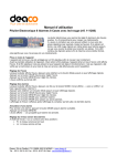
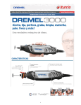
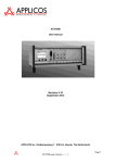
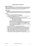
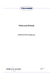
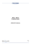
DB100/2, DB100/3, DB100/4,
DB100/2TC,
DB200/2, DB200/3
Dri-Block® Heaters
OPERATOR’S MANUAL
Issue 7
06/2014
Part code: 6106451
2
CONTENTS
INTRODUCTION ........................................................................................................ 5
BEFORE USE............................................................................................................. 6
Unpacking.................................................................................................................................................6
SAFETY AND INSTALLATION .................................................................................. 7
Warning ....................................................................................................................................................7
Operator Safety ........................................................................................................................................7
Installation ................................................................................................................................................7
Environmental Conditions ........................................................................................................................8
Guarantee.................................................................................................................................................8
SÉCURITÉ ET CONSIGNES D’INSTALLATION ....................................................... 9
Avertissement ...........................................................................................................................................9
Sécurité de l’opérateur .............................................................................................................................9
Installation ................................................................................................................................................9
Conditions environnementales .............................................................................................................. 10
Garantie ................................................................................................................................................. 10
SICHERHEITS- UND INSTALLATIONSINFORMATIONEN .................................... 11
Achtung ................................................................................................................................................. 11
Sicherheit des Bedienpersonals ............................................................................................................ 11
Inbetriebnahme...................................................................................................................................... 11
Umweltbedingungen .............................................................................................................................. 12
Garantie ................................................................................................................................................. 12
INFORMAZIONI SULLA SICUREZZA E L'INSTALLAZIONE ................................. 13
Avvertenza............................................................................................................................................. 13
Sicurezza dell'operatore ........................................................................................................................ 13
Installazione........................................................................................................................................... 13
Condizioni ambientali ............................................................................................................................ 14
Garanzia ................................................................................................................................................ 14
INFORMACIÓN DE SEGURIDAD E INSTALACIÓN ............................................... 15
Advertencia............................................................................................................................................ 15
Seguridad del operario .......................................................................................................................... 15
Instalación ............................................................................................................................................. 15
Condiciones ambientales ...................................................................................................................... 16
Garantía ................................................................................................................................................. 16
CONTACT INFORMATION ...................................................................................... 17
SPECIFICATIONS .................................................................................................... 18
DB100/2, DB100/3 and DB100/4 .......................................................................................................... 18
DB200/2 and DB200/3 .......................................................................................................................... 19
DB100/2TC ............................................................................................................................................ 20
OPERATION ............................................................................................................ 21
Installation ............................................................................................................................................. 21
Power up screen.................................................................................................................................... 22
The front panel controls ......................................................................................................................... 22
Setting the temperature units ................................................................................................................ 23
Setting the operating temperature ......................................................................................................... 23
Setting the timer .................................................................................................................................... 23
After use ................................................................................................................................................ 24
User maintenance ................................................................................................................................. 24
Calibration ............................................................................................................................................. 25
ADDITIONAL INFORMATION.................................................................................. 26
Fault Finding .......................................................................................................................................... 26
Fuses ..................................................................................................................................................... 26
Safety over-temperature cut-out............................................................................................................ 26
Support contacts.................................................................................................................................... 27
3
ACCESSORIES ........................................................................................................ 28
REPLACEMENT PARTS .......................................................................................... 29
DECLARATION OF CONFORMITY ......................................................................... 30
4
INTRODUCTION
Please read all the information in this manual before using the unit.
®
Techne Dri-Block heaters provide a safe, dry, constant temperature source in the laboratory. The
units can be used for incubation, boiling, inactivation, wet ashing, sample concentration, enzyme
analysis and many other clinical and industrial purposes.
The units cover the temperature range from ambient +5°C to 100°C or 200°C (depending on model)
using machined aluminium alloy blocks as the heat transfer medium. Independent indicator lights
indicate mains power, heater action and over-temperature cut-out. An ON/OFF switch is mounted on
the rear panel, together with the mains connector and a double fuse holder.
Temperature setting is via a simple push button display. Temperatures can be displayed in °C or °F.
Each unit also has a built-in count-down timer which can be set in 1 minute intervals to 99h 59m.
The units are constructed of painted aluminium alloy and polyphenylene sulphide (PPS) plastic,
which is strong yet lightweight and can resist sustained temperatures as high as 260°C. Even though
the units heat up rapidly, venting and highly efficient insulation ensure that the cases remain cool
enough to handle even at maximum operating temperatures.
Each unit is supplied with an extraction tool for easy removal of the insert blocks.
The operating instructions in this Operator’s Manual cover the following range of digital Dri-Block
heaters:
Voltage,
frequency
Model number
Description
DB100/2
Dri-Block heater ambient to 100°C, accepts 2 insert blocks
DB100/2/115
Dri-Block heater ambient to 100°C, accepts 2 insert blocks
DB100/3
Dri-Block heater ambient to 100°C, accepts 3 insert blocks
DB100/3/115
Dri-Block heater ambient to 100°C, accepts 3 insert blocks
DB100/4
Dri-Block heater ambient to 100°C, accepts 4 insert blocks
DB100/4/115
Dri-Block heater ambient to 100°C, accepts 4 insert blocks
DB100/2TC
DB100/2TC/115
®
®
230V, 50-60Hz
®
115V, 50-60Hz
®
230V, 50-60Hz
®
115V, 50-60Hz
®
230V, 50-60Hz
®
115V, 50-60Hz
®
Dri-Block heater ambient to 100°C, accepts 2 insert blocks,
twin control
®
Dri-Block heater ambient to 100°C, accepts 2 insert blocks,
twin control
230V, 50-60Hz
115V, 50-60Hz
®
230V, 50-60Hz
®
230V, 50-60Hz
®
230V, 50-60Hz
®
115V, 50-60Hz
DB200/2
Dri-Block heater ambient to 200°C, accepts 2 insert blocks
DB200/2/115
Dri-Block heater ambient to 200°C, accepts 2 insert blocks
DB200/3
Dri-Block heater ambient to 200°C, accepts 3 insert blocks
DB200/3/115
Dri-Block heater ambient to 200°C, accepts 3 insert blocks
The features of individual models are outlined in the Specifications section of this manual.
®
®
Note: This manual covers the digital Dri-Block heater range. The analogue Dri-Block heaters DB-2A,
DB-3 and DB-3A are covered in a separate user manual.
5
BEFORE USE
®
Before using the Dri-Block heater please make sure you have read this manual carefully. If there is
any doubt relating to the proper use of this equipment, the staff at Bibby Scientific Ltd. or your
supplier will be happy to assist you.
UNPACKING
When unpacking the unit please ensure that the following have been removed from the packaging:
®
•
Dri-Block heater
•
6101308 Extraction tool
•
Mains cables (UK and EU or US)
•
Operator’s manual
•
Guarantee card
The user is advised to keep the original packaging in case the instrument ever needs to be returned
for service or repair. Bibby Scientific Ltd. accepts no responsibility for damage incurred unless the
unit is correctly packed and transported in its original packaging.
®
The Dri-Block heater range
6
SAFETY AND INSTALLATION
®
Please read all the information in this manual before using the Dri-Block heater.
WARNING
HIGH TEMPERATURES ARE DANGEROUS: they can cause serious burns to operators and ignite
combustible material.
Techne have taken great care in the design of these units to protect operators from hazards, but
operators should pay attention to the following points:
•
USE CARE AND WEAR PROTECTIVE GLOVES TO PROTECT HANDS
•
DO NOT use combustible substances near hot objects
•
DO NOT operate the instrument in the vicinity of inflammable liquids or gases.
•
DO NOT place any liquid directly into the instrument.
OPERATOR SAFETY
All operators of Techne equipment must have available the relevant literature needed to ensure their
safety. It is important that only suitably trained personnel operate this equipment, in accordance with
the instructions contained in this manual and with general safety standards and procedures. If the
equipment is used in a manner not specified by Bibby Scientific Ltd. the protection provided by the
equipment to the operator may be impaired.
All Techne instruments are designed to conform to international safety requirements and are fitted
with an over-temperature cut-out.
If a safety problem should be encountered, switch off the unit at the mains socket and remove the
plug from the electricity supply.
INSTALLATION
The instrument should be carried using both hands. Never move or carry the instrument when in use
or connected to the mains electricity supply.
1. All Techne instruments are supplied with a power cable; this may be integral or plug-in.
2.
Before connecting the instrument to the mains electricity supply, check the voltage
against the rating plate (located on the back of the unit). Please note that the unit
must be earthed to ensure proper electrical safety. Connect the mains cable to a
suitable plug according to the table below.
Connections
Live
Neutral
Earth
230V, 50/60Hz
115V, 50/60Hz
Brown
Black
Blue
White
Green/yellow
Green
UK ONLY: The fused plug supplied with the mains cable is fitted with a 5 amp fuse to protect the
instrument and the operator.
Note that units marked 230V on the rating plate work at 207V; units marked 115V work at 104V. In
both cases, however, the heating rate will degrade by approximately 8%.
3. Place the unit on a suitable flat bench or in a fume cupboard if required, ensuring that the air inlet
vents on the underside are free from obstruction.
4. Plug the mains cable into the socket on the back of the instrument.
5. Switch on the instrument. Symbols on or near the power switch of the unit have the following
meanings:
7
I
Mains Switch On
O
Mains Switch Off
Replacement cable
2
Should the mains lead need replacement, a cable of 1mm of harmonized code H05VV-F connected
to an IEC320 plug should be used. IF IN DOUBT CONSULT A QUALIFIED ELECTRICIAN.
ENVIRONMENTAL CONDITIONS
®
The Dri-Block heater is designed operate under the following conditions:
•
Indoor use
•
Ambient temperature range +5ºC to +40ºC
•
Altitude to 2000m
•
Relative humidity up to 80%
•
Mains supply fluctuations not exceeding 10%
•
Over voltage category II IEC 60364-4-443
•
Pollution degree 2
•
Use with a minimum distance all-around of 200mm from walls or other items
Note: The control specifications are quoted at an ambient temperature of 20ºC. The specification
may deteriorate outside an ambient temperature of between 10ºC and 30ºC.
The instrument has been tested for radio frequency interference and is certified under EN61326.
GUARANTEE
The instrument is guaranteed against any defect in material or workmanship for the period specified
on the enclosed guarantee card. This period is effective from the date of purchase; within this period
all defective parts will be replaced free of charge provided that the defect is not the result of an
accident, misuse or negligence. Servicing under this guarantee should be obtained from the supplier
of the instrument.
This manual has been prepared for the convenience of Techne’s customers and nothing in this
manual shall be taken as a warranty, condition or representation concerning the description,
merchantability, fitness for purpose or otherwise of the unit or components.
Notwithstanding the description and specification(s) of the instruments contained in the operator’s
manual, Techne reserves the right to make such changes as it sees fit to the instruments or to any of
the components.
8
SÉCURITÉ ET CONSIGNES D’INSTALLATION
®
Veuillez lire attentivement toutes les instructions de ce document avant d’utiliser le Dri-Block heater.
AVERTISSEMENT
Les TEMPÉRATURES ÉLEVÉES SONT DANGEREUSES car elles peuvent provoquer de graves
brûlures chez l’opérateur et enflammer les matériaux combustibles.
Techne a apporté un soin tout particulier à la conception de ces appareils de façon à assurer une
protection maximale des opérateurs, mais il est recommandé aux utilisateurs de porter une attention
spéciale aux points suivants :
•
PROCEDER AVEC PRUDENCE ET PORTER DES GANTS POUR SE
PROTEGER LES MAINS
•
NE PAS utiliser de matériaux combustibles auprès d’objets chauds.
•
NE PAS utiliser l’appareil à proximité de liquides ou de gaz inflammables
•
NE PAS verser de liquides directement dans l’appareil.
SECURITE DE L’OPÉRATEUR
Tous les utilisateurs de produits Techne doivent avoir pris connaissance des consignes et instructions
nécessaires à la garantie de leur sécurité. Important: cet appareil doit impérativement être manipulé
par un personnel qualifié et être utilisé selon les instructions données dans ce document, en accord
avec les normes et procédures de sécurité générales. Dans le cas où cet appareil ne serait pas utilisé
selon les consignes précisées par Bibby Scientific Ltd., la protection pour l’utilisateur ne serait alors
plus garantie.
Tous les appareils Techne sont conçus pour répondre aux normes de sécurité internationales et sont
dotés d’un coupe-circuit en cas de surchauffe.
En cas de problème de sécurité, couper l’alimentation électrique au niveau de la prise murale et
enlevez la prise connectée à l’appareil.
INSTALLATION
Porter l'appareil à deux mains. Ne jamais déplacer ou transporter l’appareil lorsqu’il est en
fonctionnement ou branché à l’alimentation électrique.
1. Tous les appareils Techne sont livrés avec un câble d'alimentation, qui peut être intégré à l'appareil
ou à raccorder.
2.
Avant de raccorder l’appareil à l’alimentation électrique sur secteur, vérifier la tension
requise indiquée sur la plaque d’identification (située au dos de l’appareil). Il est
important que l’appareil soit relié à la terre pour assurer la protection électrique
requise. Brancher le câble secteur sur une prise appropriée, voir tableau ci-après.
Connexions
230V, 50/60 Hz
115V, 50/60 Hz
Phase
Marron
Noir
Neutre
Bleu
Blanc
Terre
Vert/jaune
Vert
ROYAUME-UNI SEULEMENT: La prise avec fusible intégré fournie avec le câble secteur est
munie d’un fusible 5 A destiné à protéger l’appareil et l’utilisateur.
Remarque : les appareils dont la plaque indique 230 V peuvent fonctionner sur 207 V, et ceux dont
la plaque indique 115 V peuvent fonctionner sur 104 V. Dans les deux cas cependant, la capacité
de chauffage diminuera d’environ 8 %.
9
3. Placer l’appareil sur une surface plane ou si nécessaire sous une hotte d’aspiration, veiller à ce
que les trous d’aération situés sous l’appareil ne soient pas obstrués.
4. Raccorder le câble d’alimentation à la prise située à l’arrière de l’appareil.
5. Allumer l'appareil. Les symboles situés sur ou à côté de l’interrupteur de l’appareil ont la
signification suivante :
I
Interrupteur secteur en position Marche
O
Interrupteur secteur en position Arrêt
Câble de rechange
S’il s’avère nécessaire de remplacer le cordon d’alimentation, utiliser un câble de 1 mm² conforme à
la norme H05VV-F relié à une prise IEC320. EN CAS DE DOUTE, CONSULTER UN ELECTRICIEN
QUALIFIE.
CONDITIONS ENVIRONNEMENTALES
®
Le Dri-Block heater est conçu pour fonctionner dans les conditions suivantes:
•
Pour un usage intérieur seulement
•
Température ambiante +5°C à +40°C
•
Altitude inférieure à 2000m
•
Humidité relative ne dépassant pas 80%
•
Fluctuations de l’alimentation n’excédant pas 10% de la valeur nominale
•
Catégorie II IEC 60364-4-443 de surtension
•
Degré de pollution 2
•
Utiliser à une distance minimale sur le pourtour de 200mm par rapport aux murs et autres
équipements
Remarque: Les paramètres sont indiqués pour une température ambiante de 20°C. Ces
caractéristiques peuvent se détériorer en dehors d’une température ambiante de 10 à 30°C.
L’appareil a été testé en matière de radiofréquences et est certifié selon la norme EN61326.
GARANTIE
L’appareil est garanti contre tout défaut de matériaux ou vice de fabrication pendant la période
précisée sur la carte de garantie jointe. Cette période s’applique à compter de la date d’achat. Au
cours de cette période, toutes les pièces défectueuses seront remplacées gratuitement dans la
mesure où la défaillance n’est pas due à un accident, une mauvaise utilisation ou une négligence.
Toute réparation sous garantie sera effectuée par le fournisseur.
Le présent manuel a été exclusivement rédigé à l’attention des clients de la marque Techne et rien
dans son contenu ne doit être pris comme une garantie, une condition ou une affirmation concernant
la description, la commercialisation, l’adéquation à un usage particulier de l'appareil ou de ses
composants.
Malgré la description et les caractéristiques techniques des appareils données dans le manuel de
l’utilisateur, la société Techne se réserve le droit d’apporter les changements nécessaires à l’appareil
ou à tout élément qui entre dans sa composition.
10
SICHERHEITS- UND INSTALLATIONSINFORMATIONEN
®
Lesen Sie diese Anleitung vor Verwendung des Dri-Block heater bitte sorgfältig durch.
ACHTUNG
HOHE TEMPERATUREN STELLEN EINE GEFAHRENQUELLE DAR. Sie können schwere
Brandverletzung verursachen und brennbare Stoffe entzünden.
Techne hat bei der Konstruktion dieses Gerätes sehr darauf geachtet, daß der Bediener vor
Gefahren geschützt ist. Dennoch sollten Sie auf die folgenden Punkte achten:
•
UMSICHTIG VORGEHEN UND SCHUTZHANDSCHUHE TRAGEN
•
KEINE brennbaren Stoffe in der Nähe heißer Gegenstände verwenden
•
Das Gerät NICHT in der Nähe entzündlicher Flüssigkeiten oder Gase betreiben
•
Flüssigkeiten NICHT direkt auf das Gerät auftragen.
SICHERHEIT DES BEDIENPERSONALS
Alle Benutzer von Techne Geräten müssen Zugang zu der entsprechenden Literatur haben, um ihre
Sicherheit zu gewähren. Es ist wichtig, daß diese Geräte nur von entsprechend geschultem Personal
betrieben werden, das die in dieser Gebrauchsanweisung enthaltenen Maßnahmen und allgemeine
Sicherheitsbestimmungen und - vorkehrungen beachtet. Wenn das Gerät anders eingesetzt wird als
vom Hersteller empfohlen, kann dies die persönliche Sicherheit des Anwenders beeinträchtigen.
Die Geräte von Techne entsprechen den internationalen Sicherheitsbestimmungen und sind mit einem
automatischen Übertemperaturabschalter ausgestattet.
Wenn ein Sicherheitsproblem auftreten sollte, muß das Gerät ausgeschaltet und vom Stromnetz
getrennt werden.
INBETRIEBNAHME
Das Gerät mit beiden Händen tragen. Das Gerät unter keinen Umständen transportieren, wenn es in
Betrieb ist, oder während das Gerät noch am Netz angeschlossen ist.
1.
Alle Geräte von Techne werden mit einem Netzkabel geliefert, das entweder eingesteckt wird
oder fest mit dem Gerät verbunden ist.
2.
Vor dem Anschluss bitte kontrollieren, ob die Stromversorgung den Angaben auf dem
Typenschild (auf der Geräterückseite) entspricht. Um die elektrische Sicherheit zu
gewährleisten, muss dieses Gerät geerdet werden. Schließen Sie das Netzkabel
entsprechend der folgenden Tabelle an einen geeigneten Stecker an.
Anschluss
230V, 50/60Hz
115V, 50/60Hz
Phase
Braun
Schwarz
Neutral
Blau
Weiß
Grün/Gelb
Grün
Erde
NUR FÜR GROSSBRITANNIEN: der mit dem Netzkabel gelieferte Sicherungsstecker enthält
eine 5 Amp. Sicherung zum Schutz des Geräts und des Anwenders.
Geräte, die für 230 Volt ausgelegt sind, können auch bei 207 Volt arbeiten, Geräte für 115 Volt
auch bei 104 Volt. In beiden Fällen verringert sich die Aufheizrate um ca. 8%.
3.
Stellen Sie das Gerät auf einen geeigneten ebenen Tisch oder in einem Abzugsschrank auf und
sorgen Sie dafür, dass die Lufteinlassschlitze auf der Geräteunterseite nicht blockiert sind.
4.
Stecken Sie das Netzkabel in die Buchse auf der Geräterückseite ein.
5.
Schalten Sie das Gerät ein:
11
I
Netzschalter Ein
O
Netzschalter Aus
Ersatzkabel
2
Bei einem eventuellen Austausch des Netzkabels wird ein Kabel vom Typ H05VV-F mit 1 mm
Adernquerschnitt und Europastecker (IEC 320) benötigt. IM ZWEIFELSFALL EINEN ELEKTROFACHMANN HINZUZIEHEN.
UMWELTBEDINGUNGEN
®
Der Dri-Block heater ist für den Einsatz unter folgenden Bedingungen ausgelegt:
•
Gebrauch in Innenräumen
•
Umgebungstemperatur zwischen +5ºC to +40ºC
•
Höhe: bis zu 2000 m
•
Relative Feuchte nicht über 80%
•
Netzspannungsschwankungen nicht über 10%
•
Überspannungsklasse 2 IEC 60364-4-443
•
Verschmutzungsgrad 2
•
Der Mindestabstand zwischen dem Gerät und umgebenden Wänden oder Gegenständen muss
200mm betragen
Hinweis: Die Gerätespezifikationen beziehen sich auf eine Umgebungstemperatur von 20ºC und
können sich außerhalb des Bereichs 10ºC bis 30ºC verschlechtern.
Das Gerät wurde auf HF-Störeinflüsse geprüft und entspricht den EMV-Bedingungen nach EN61326.
GARANTIE
Techne gewährleistet, dass dieses Gerät für den auf der Garantiekarte angegebenen Zeitraum keine
Herstellungs- und Materialmängel aufweist. Dieser Zeitraum tritt ab dem Verkaufsdatum in Kraft.
Innerhalb dieses Zeitraums werden alle defekten Teile kostenlos ausgetauscht, soweit der Defekt
nicht auf einen Unfall, Missbrauch oder Nachlässigkeit zurückzuführen ist. Wartungsarbeiten, die
unter diese Garantie fallen, müssen von der Verkaufsstelle für dieses Gerät gehandhabt werden.
Diese Anleitung wurde zur Information der Kunden von Techne erstellt und stellt in keinster Weise
eine Gewährleistung, Bedingung oder Darstellung bezüglich der Beschreibung, Marktgängigkeit oder
Zweckdienlichkeit dieser Geräte oder Bauteile dar.
Unabhängig von Beschreibung und Spezifikation(en) des hier beschriebenen Geräts behält sich
Techne das Recht vor, Änderungen an diesem Gerät oder dessen Bauteilen vorzunehmen.
12
INFORMAZIONI SULLA SICUREZZA E L'INSTALLAZIONE
®
Leggere attentamente il presente manuale prima di usare il Dri-Block heater.
AVVERTENZA
Le ALTE TEMPERATURE SONO PERICOLOSE in quanto possono provocare serie ustioni agli
operatori e dare fuoco al materiale combustibile.
La Techne ha posto particolare cura nel progettare questo strumento, al fine di proteggere gli
operatori da eventuali pericoli, ma gli utilizzatori devono prestare attenzione ai seguenti punti:
•
PRESTARE ATTENZIONE ED INDOSSARE GUANTI PROTETTIVI PER LE
MANI
•
NON usare sostanze combustibili vicino ad oggetti caldi
•
NON mettere in funzione lo strumento nei pressi di liquidi o gas infiammabili
•
NON collocare alcun tipo di liquido direttamente nello strumento.
SICUREZZA DELL'OPERATORE
Il personale che utilizza l’apparecchiatura Techne deve avere a disposizione la documentazione
necessaria al fine di assicurare la loro incolumità. È importante che solo personale adeguatamente
addestrato utilizzi questo apparecchio, in conformità alle istruzioni contenute in questo manuale e nel
rispetto delle normative e procedure generali di sicurezza. Se l’apparecchio è utilizzato in modo non
specificato da Bibby Scientific Ltd., la protezione fornita dall’apparecchiatura all’utilizzatore potrebbe
essere a rischio.
Tutte le unità Techne sono state progettate in conformità ai requisiti internazionali di sicurezza e sono
equipaggiate con un interruttore anti surriscaldamento.
Se si dovesse verificare qualche problema di sicurezza, disconnettere l’apparecchio dalla rete.
INSTALLAZIONE
Occorre trasportare lo strumento usando entrambe le mani. Non spostare né trasportare lo
strumento quando è in funzione o collegato all’alimentazione elettrica di rete.
1.
Tutti gli strumenti Techne sono forniti con un cavo di alimentazione; può essere integrale o
plugin.
2.
Prima di collegare lo strumento all'alimentazione elettrica di rete, controllare la
tensione confrontandola con la targhetta riportante i valori nominali (si trova sul retro
dell'unità). Notare che al fine di garantire la corretta sicurezza elettrica, occorre
che l'unità sia messa a terra. Collegare il cavo di rete ad una presa idonea secondo
la tabella riportata alla pagina successiva.
Connessione
230V, 50/60Hz
115V, 50/60Hz
Sotto tensione
Marrone
Nero
Neutro
Blu
Bianco
Terra
Verde/giallo
Verde
SOLO REGNO UNITO: la spina con fusibile fornita con il cavo di rete è dotata di un fusibile da 5
Amp per proteggere lo strumento e l'utente.
Tenere presente che gli apparecchi riportanti sulla targhetta 230 V funzionano a 207V. Gli
apparecchi riportanti 115V funzionano a 104V. Comunque, in entrambi i casi la velocità di
riscaldamento diminuirà approssimativamente dell’8%.
13
3.
Collocare l'unità su un banco piano idoneo o in una cappa aspirante se necessario, assicurandosi
che gli sfiati delle prese d'aria nella parte inferiore non siano ostruiti.
4.
Inserire il cavo di rete nella presa che si trova sul retro dello strumento.
5.
Accendere lo strumento:
I
Interruttore di rete Acceso
O
Interruttore di rete Spento
Cavo di ricambio
2
Qualora occorra sostituire il cavo di rete, si dovrà utilizzare un cavo di 1mm codice armonizzato
H05VV-F collegato ad una spina IEC 320. IN CASO DI DUBBIO, RIVOLGERSI A UN
ELETTRICISTA QUALIFICATO.
CONDIZIONI AMBIENTALI
®
Il Dri-Block heater è stato progettato per funzionare nelle seguenti condizioni:
•
uso interno
•
range di temperatura ambiente da +5ºC a +40ºC
•
altitudine massima 2000 m.
•
umidità relativa non superiore all’80%
•
oscillazione dell’alimentazione di rete non superiore al 10%
•
categoria di sovratensione II IEC 60364-4-443
•
grado di inquinamento 2
•
Con distanza minima tra i lati dell’apparecchio e il muro o altri oggetti di almeno 200mm
Nota: le specifiche di controllo sono indicate ad una temperatura ambiente di 20ºC. Le specifiche
potrebbero peggiorare fuori da una temperatura ambiente compresa tra 10ºC e 30ºC.
Lo strumento è stato collaudato per interferenze da radiofrequenze ed è certificato secondo la norma
EN61326.
GARANZIA
Lo strumento è garantito da qualsiasi difetto nei materiali o nella lavorazione per il periodo specificato
nella scheda di garanzia allegata. Questo periodo è valido dalla data di acquisto; entro tale periodo,
tutte le parti difettose saranno sostituite gratuitamente, a condizione che il difetto non sia la
conseguenza di un incidente, un uso improprio o negligenza. L'assistenza secondo quanto stabilito
dalla presente garanzia deve essere ottenuta dal fornitore dello strumento.
Il presente manuale è stato preparato ad uso dei clienti di Techne e niente di quanto in esso
contenuto costituisce garanzia, condizione o rappresentanza riguardo la descrizione, la
commerciabilità, l'idoneità allo scopo o altrimenti dell'unità o dei componenti.
Nonostante la descrizione e le specifiche dello strumento contenuti nel manuale dell'operatore,
Techne si riserva il diritto di apportare le modifiche ritenute opportune agli strumenti o a qualsiasi loro
componente.
14
INFORMACIÓN DE SEGURIDAD E INSTALACIÓN
®
Lea atentamente este manual antes de utilizar el Dri-Block heater.
ADVERTENCIA
LAS ALTAS TEMPERATURAS SON PELIGROSAS, ya que pueden ocasionar quemaduras graves a
los operarios y prender el material combustible. Techne ha puesto gran cuidado en el diseño de estos
aparatos para proteger al usuario de cualquier peligro; aún así se deberá prestar atención a los
siguientes puntos:
•
TENGA CUIDADO Y LLEVE
PROTEGERSE LAS MANOS
GUANTES
DE
PROTECCIÓN
•
NO utilice sustancias combustibles cerca de objetos calientes
•
NO utilice el instrumento cerca de líquidos o gases inflamables
•
NO coloque un líquido directamente en el instrumento.
PARA
SEGURIDAD DEL OPERARIO
Todos los usuarios de equipos Techne deben disponer de la información necesaria para asegurar su
seguridad. De acuerdo con las instrucciones contenidas en este manual y con las normas y
procedimientos generales de seguridad, es muy importante que sólo personal debidamente
capacitado opere estos aparatos. De no ser así, la protección que el equipo le proporciona al usuario
puede verse reducida.
Todos los equipos Techne han sido diseñados para cumplir con los requisitos internacionales de
seguridad y traen incorporados un sistema de desconexión en caso de sobre temperatura.
En caso de que surgiera un problema de seguridad, desconecte el equipo de la red.
INSTALACIÓN
El instrumento se debe transportar con las dos manos. No mueva ni lleve el instrumento cuando se
utilice o esté conectado al suministro eléctrico principal.
1.
Todos los instrumentos Techne se suministran con un cable de alimentación, que puede ser
integrado o ‘enchufable’.
2.
Antes de conectar el instrumento al suministro eléctrico, compruebe que el voltaje
coincida con el indicado en la placa de régimen (situada en la parte trasera de la
unidad). El instrumento debe disponer de una toma de tierra para garantizar la
seguridad eléctrica adecuada. Conecte el cable de alimentación a un enchufe
adecuado según la siguiente tabla.
Conexión
Con corriente
Neutro
Toma de tierra
230V, 50/60Hz
115V, 50/60Hz
Marrón
Negro
Azul
Blanco
Verde/amarillo
Verde
SÓLO PARA EL REINO UNIDO: El enchufe suministrado con el cable de alimentación incluye
un fusible de 5 amperios para ofrecer protección al instrumento y al usuario.
Asegúrese de que los equipos marcados 230V en la placa indicadora funcionan a 207V y de
que los equipos marcados 115V funcionan a 104V. No obstante, en ambos casos la velocidad
de calentamiento se verá reducida en un 8% aproximadamente.
15
3.
Sitúe la unidad sobre una mesa plana o en una campana de laboratorio si es necesario, y
asegúrese de que los orificios de ventilación situados en la parte inferior no tienen ninguna
obstrucción.
4.
Conecte el cable de alimentación en el enchufe situado en la parte trasera del instrumento.
5.
Encienda el instrumento:
I
Interruptor de alimentación encendido
O
Interruptor de alimentación apagado
Cable de repuesto
2
Si es necesario sustituir el cable de alimentación, se debe utilizar un cable de 1mm de código
armonizado H05VV, conectado a un enchufe IEC320. EN CASO DE DUDA, PÓNGASE EN
CONTACTO CON UN ELECTRICISTA.
CONDICIONES AMBIENTALES
®
El Dri-Block heater está diseñado para utilizarse en las condiciones siguientes:
•
Uso en interior
•
Intervalo de temperatura ambiente +5ºC a +40ºC
•
Altitud: hasta 2000 m
•
Humedad relativa no superior al 80%
•
Fluctuaciones del suministro eléctrico no superiores al 10%
•
Categoría de sobrevoltaje II IEC 60364-4-443
•
Nivel de contaminación 2
•
Separado de paredes u otros objetos a una distancia mínima de 200mm
Nota: Las especificaciones de control corresponden a una temperatura ambiental de 20ºC. Las
especificaciones pueden empeorar si se utiliza el instrumento fuera del intervalo de temperatura
comprendido entre 10ºC y 30ºC.
Se han realizado pruebas para comprobar la interferencia de radiofrecuencia del instrumento, el cual
cumple la normativa EN61326.
GARANTÍA
El instrumento está garantizado contra cualquier defecto en el material o la fabricación durante el
período especificado en la tarjeta de garantía que se adjunta. Este período entra en vigor a partir de
la fecha de compra. Durante este período, se reemplazarán sin cargo alguno todas las piezas
defectuosas, a condición que el defecto sea resultado de un accidente, uso incorrecto o negligencia.
El distribuidor del instrumento proporcionará información sobre las reparaciones realizadas bajo esta
garantía.
Este manual se ha preparado con una finalidad informativa para los clientes de Techne y ninguna
parte del manual se deberá considerar como una garantía, condición o reflejo con respecto a la
descripción, comerciabilidad, idoneidad para un fin determinado o de otro tipo de la unidad o sus
componentes.
Con independencia de la descripción y las especificaciones del instrumento que se indican en el
manual del operario, Techne se reserva el derecho de realizar cambios en el instrumento o en
cualquiera de sus componentes cuando lo estime oportuno.
16
CONTACT INFORMATION
For technical, sales or servicing information, contact your local Techne dealer or:
UK
Bibby Scientific Ltd.
Beacon Road
Stone
Staffordshire
ST15 0SA
UK
Tel: +44 (0)1785 812121
Fax: +44 (0)1785 810405
E-mail: [email protected]
www.techne.com
North and South America
Bibby Scientific US Inc. t/a Techne Inc.
3 Terri Lane, Suite 10
Burlington, N.J. 08016
USA
Toll Free (in NA): 800-225-9243
Tel: +1 609 589 2560
Fax: +1 609 589 2571
E-mail: [email protected]
www.techneusa.com
France
Bibby Scientific Limited
Bâtiment Le Deltaparc Parc Silic PN2
7 rue du Canal
BP 55437 VILLEPINTE
95944 ROISSY Charles de Gaulle
France
Tel: +33(0)148 63 78 03
Fax: +33(0)148 63 78 01
E-mail: [email protected]
www.bibby-scientific.com
Asia
Bibby Scientific - Singapore
Prudential Tower, Level 26
30 Cecil Street
Singapore 049712
Tel: +65 6631 2976
Fax: +44 (0) 1785 810405
e-mail: [email protected]
www.bibby-scientific.com
Middle East
Bibby Scientific Middle East Ltd.
PO Box 27887, Engomi 2433
Nicosia
Cyprus
Tel: +357 22 660 423
Fax: +357 22 660 424
e-mail: [email protected]
17
SPECIFICATIONS
DB100/2, DB100/3 AND DB100/4
DB100/2
DB100/2/115
DB100/3
DB100/3/115
DB100/4
DB100/4/115
2
3
4
Temperature display
5 character LED
5 character LED
5 character LED
Working temperature range
Ambient +5°C to
100°C
Ambient +5°C to
100°C
Ambient +5°C to
100°C
0°C
0°C
0°C
Set point resolution
0.1°C
0.1°C
0.1°C
Set point accuracy at 37°C
≤±1°C
≤±1°C
≤±1°C
Set point accuracy at 100°C
≤±1.5°C
≤±1.5°C
≤±1.5°C
Temperature stability at 37°C
≤±0.1°C
≤±0.1°C
≤±0.1°C
Temperature stability at 100°C
≤±0.15°C
≤±0.15°C
≤±0.15°C
Max. temperature variation
within a block
<0.2°C at 37°C
<0.3°C at 100°C
<0.2°C at 37°C
<0.3°C at 100°C
<0.2°C at 37°C
<0.3°C at 100°C
Max. temperature variation
between similar blocks
<0.5°C at 37°C
<1.0°C at 100°C
<0.5°C at 37°C
<1.0°C at 100°C
<0.5°C at 37°C
<1.0°C at 100°C
8 minutes
7 minutes
7 minutes
Yes
Yes
Yes
1min / 99h59min
1min / 99h59min
1min / 99h59min
Thermal fuse
Thermal fuse
Thermal fuse
202 x 260 x 105mm
279 x 260 x 105mm
356 x 260 x 105mm
230V or 115V,
50-60Hz
230V or 115V,
50-60Hz
230V or 115V,
50-60Hz
300W
450W
600W
5kg
6kg
7kg
Specification
Number of insert blocks
Minimum set temperature
Heat up time 25°C to 100°C
Countdown Timer with audible
beeps
Minimum / Maximum timer
Safety over-temp cut-out
Overall dimensions (W x D x H)
Electrical supply
Power
Shipping weight
Note: The control specifications are quoted for an ambient temperature of 20°C for units fitted with
2, 3 or 4 insert blocks type F3506. The specification will be closely held if the ambient temperature is
in the range 10°C to 30°C. Outside this range the quoted figures may deteriorate but the unit will still
work safely.
Note: Different block inserts may take different amounts of time to equilibrate to the same
temperature.
18
DB200/2 AND DB200/3
DB200/2
DB200/2/115
DB200/3
DB200/3/115
2
3
5 character LED
5 character LED
Ambient +5°C to 200°C
Ambient +5°C to 200°C
0°C
0°C
Set point resolution
0.1°C
0.1°C
Set point accuracy at 37°C
≤±1°C
≤±1°C
Set point accuracy at 100°C
≤±1°C
≤±1°C
Temperature stability at 37°C
≤±0.1°C
≤±0.1°C
Temperature stability at 100°C
±0.15°C
±0.15°C
Max. temperature variation within a block
<0.2°C at 37°C
<0.2°C at 100°C
<0.2°C at 37°C
<0.2°C at 100°C
Max. temperature variation between
similar blocks
<0.5°C at 37°C
<1.5°C at 100°C
<0.5°C at 37°C
<1.5°C at 100°C
Heat up time 25°C to 100°C
8 minutes
7 minutes
Heat up time 25°C to 200°C
23 minutes
19 minutes
Yes
Yes
1min / 99h59min
1min / 99h59min
Thermal fuse
Thermal fuse
202 x 260 x 105mm
279 x 260 x 105mm
230V or 115V, 50-60Hz
230V or 115V, 50-60Hz
300W
450W
5kg
6kg
Specification
Number of insert blocks
Temperature display
Working temperature range
Minimum set temperature
Countdown Timer with audible beeps
Minimum / Maximum timer
Safety over-temp cut-out
Overall dimensions (W x D x H)
Electrical supply
Power
Shipping weight
Note: The control specifications are quoted for an ambient temperature of 20°C for units fitted with
2, 3 or 4 insert blocks type F3506. The specification will be closely held if the ambient temperature is
in the range 10°C to 30°C. Outside this range the quoted figures may deteriorate but the unit will still
work safely.
Note: Different block inserts may take different amounts of time to equilibrate to the same
temperature.
19
DB100/2TC
Specification
Number of insert blocks
Temperature display
Working temperature range
“Temperature setting range”
Minimum set temperature
DB100/2TC
DB100/2TC/115
2
5 character LED
Ambient +5°C to 100°C
0°C
Set point resolution
0.1°C
Set point accuracy at 37°C
≤±1°C
Set point accuracy at 100°C
≤±1.5°C
Temperature stability at 37°C
≤±0.1°C
Temperature stability at 100°C
≤±0.15°C
Max. temperature variation within a block
<0.2°C at 37°C
<0.3°C at 100°C
Max. temperature variation between similar
blocks when set to the same temperature
<0.5°C at 37°C
<1.0°C at 100°C
Heat up time 25°C to 100°C
Overall dimensions (W x D x H)
Countdown Timer with audible beeps
Minimum / Maximum timer
Safety over-temp cut-out
Overall dimensions (W x D x H)
Electrical supply
Power
Shipping weight
8 minutes
279 x 260 x 105mm
Yes
1min / 99h59min
Thermal fuse
279 x 260 x 105mm
230V or 115V,
50-60Hz
300W
5kg
Note: The control specifications are quoted for an ambient temperature of 20°C for units fitted with
2, 3 or 4 insert blocks type F3506. The specification will be closely held if the ambient temperature is
in the range 10°C to 30°C. Outside this range the quoted figures may deteriorate but the unit will still
work safely.
Note: Different block inserts may take different amounts of time to equilibrate to the same
temperature.
20
OPERATION
INSTALLATION
See also the sections on Safety and Installation.
1. Place the unit on a suitable flat bench or in a fume cupboard if required, ensuring that the air inlet
vents on the underside are free from obstruction.
2. Select the insert aluminium alloy block(s) appropriate for the application. A list of available blocks
is given in the section ‘Accessories’. Ensure that both the underside of the block(s) and the top of
the hotplate are clean; efficient heat conduction between these two surfaces is essential.
Top view showing three insert blocks in place
3. Place the insert blocks onto the hotplate in the well of the unit and place the tubes containing the
sample liquid in the blocks.
4. The heater design, temperature sensor and control circuit give good temperature control and
uniformity, but it is important that there is a close fit of the tubes in the block to allow efficient heat
transfer.
5. If less than the maximum number of insert blocks are fitted it is recommended that plastic half
blocks (part code F4466) are fitted to the space either side of the aluminium block. The half blocks
have the effect of reducing heat loss, thus improving temperature stability.
Rear view
1.
2.
Power ON/OFF switch.
Mains cable socket.
6. Plug the mains cable into the socket in the rear of the unit. Connect to the mains electricity supply
with the plug provided or one wired correctly for your supply. Switch the power ON from the switch
located next to the mains input lead. The front display will then light up.
21
POWER UP SCREEN
When you first switch on, the display will initially flash the currently installed firmware version of the
unit. It will display this for 1 second and then the actual temperature of the plate will be indicated.
THE FRONT PANEL CONTROLS
The front panel controls consist of four buttons for controlling the display, a five digit LED display and
three indicators.
The front panel controls
1. Five digit LED display.
2. Power indicator. When lit, this shows that there is power to the unit.
3. Heater indicator. When this is flashing, it indicates that the heater is heating the unit or
®
controlling the temperature. If the Dri-Block is above the set temperature then the indicator
will be off.
4. Over-temperature indicator. If this is lit, it indicates that the unit has developed a fault and the
over-temperature cut-out has been triggered. This will cause the heater to be switched off and
the unit will begin to cool even if the heater light is on. The unit should be returned to Bibby
Scientific or its authorised agent for investigation.
5. Set/reset. Press to show the set temperature. If the timer is activated, pressing and holding
this button deactivates the timer. This button also silences the beeper.
6. Up arrow button. Used together with the set/reset button or timer button to increase the set
temperature or time. Used together with the Down arrow button, this button can be used to
change the temperature display from °C to °F.
7. Down arrow button. Used together with the set/reset button or timer button to decrease the set
temperature or time.
8. Timer. Press to set or activate the timer. This button also silences the beeper.
22
SETTING THE TEMPERATURE UNITS
1. Press the Up arrow and Down arrow buttons together to toggle between °F and °C.
Note: When the unit is tuned off, on subsequent power-up the units will revert to °C.
SETTING THE OPERATING TEMPERATURE
1. To display the set temperature on the digital display, press and hold the set/reset button.
2. To adjust the set temperature, press the set/reset button and hold it while pressing the Up or
Down arrow buttons. Each press of the Up arrow or Down arrow buttons will increase or
decrease the set temperature by 0.1°C. If the buttons are held down the temperature change
will accelerate to 20°C per second.
3. When the set/reset button is released, the current heater temperature is displayed.
4. The heater indicator will flash if the new set temperature is higher than the current heater
temperature and will continue to flash to show that the unit is controlling the temperature.
5. The heater indicator will turn off if the new set temperature is lower than the current heater
temperature and will only start to flash when approaching the set temperature.
6. For optimal accuracy, allow the block inserts to equilibrate to the set temperature for about 30
minutes.
DB100/2TC
The model D100/2TC accommodates 2 aluminium blocks with independent temperature controls so
that each block may be set to a different temperature. The operation of the controls for each block is
as described above.
If using this model with only one block in place, the side with no block should have its set temperature
adjusted to 30°C.
Note: Due to variations in heat losses with different designs of insert block, the actual temperature
may vary. The units are calibrated using model F3506 insert blocks. If you need to control the
temperature to a greater accuracy than the instrument’s set point, place a thermometer in a
designated hole in one of the blocks. For greater accuracy still, you can place a thermometer in the
sample liquid in one of the test tubes.
In either of these cases, it may be necessary to readjust the set temperature to achieve the precise
temperature required. Allow the temperature of the unit to stabilise after each adjustment. There will
be a time lag between the heater plate and the insert block achieving the set temperature due to the
thermal contact between them.
SETTING THE TIMER
1. To set the timer, press and hold the timer button and press the Up or Down arrow buttons.
Each press of the Up arrow or Down arrow buttons will increase or decrease the set time by 1
minute. If the buttons are held down, the time change will accelerate to 200 min per second.
2. Release the timer button to activate the timer. An audible beep will be heard once the timer is
activated.
3. When the count-down time has completed, an audible beep will be heard and the display will
show the word ‘End’ alternatively with the current heater temperature. Press the set/reset
button to cancel the beeper. The unit will start to cool to ambient once the count-down time
has completed.
4. To stop the timer at any point during the count-down period, press and hold the set/reset
button or the timer button until the word ‘Stop’ appears and an audible beep is heard.
23
5. To display the current heater temperature while the timer is active, press the timer button. The
display will show the heater temperature and the letter ‘t’ will flash on the left hand side
indicating the timer is counting down. Press the timer button again to revert to the timer countdown.
6. To re-run the same timer count-down, press the timer button until an audible beep is heard.
7. To turn the timer function off, press and hold the timer button and press the Down arrow
button until the word ‘OFF’ appears.
AFTER USE
When you have finished heating samples, remember that parts of the unit – the tubes, blocks and
associated accessories – may be very hot. Take the precautions listed in the section Safety and
Installation. We recommend that the blocks should be allowed to cool to 70°C or below before being
removed from the heating unit.
To remove an insert block, screw the extractor tool into the threaded hole and lift the block out
®
vertically. Never leave the extractor tool in the block while it is being used in the Dri-Block heater.
Removing an insert block with the extractor tool
USER MAINTENANCE
®
Before cleaning your unit, disconnect it from the power supply. The outer case of the Dri-Block
heater may be cleaned with a cloth dipped in water or ethanol (methanol can also be used). No part
of the case or cover should be immersed in the solvents. Do not use aggressive solvents such as
acetone or abrasive cleaners. Do not use bleach or strong acids.
Before using any cleaning or decontamination method except those recommended here, the
responsible person should check with Techne that the proposed method will not damage the
equipment.
24
CALIBRATION
Note that if you change the calibration from that set at the factory you may change the
calibration at all temperatures. You may get different calibration with different blocks.
Make sure that you have good thermal contact between the insert blocks and the heater plate in the
®
Dri- Block heater. For best results, push all the block inserts to the right hand side so they are
touching. In order to ensure that the calibration you are setting is correct, you will need to use an
independently calibrated temperature probe or thermometer.
®
First, measure the actual temperature of the particular block you want to use in the Dri-Block heater
using the calibrated probe or thermometer. If the calibration is not correct then you can follow the
procedure outlined below. Before you begin, make sure that the block and the unit are below 35°C.
1. Set the temperature display to the lowest setting. This will ensure that the block is at ambient
temperature for the next procedure.
2. Insert your calibrated probe or thermometer into the thermometer hole of the right hand block
insert. A little silicone oil can be placed in the hole if necessary to give a better heat transfer.
3. Press and hold the Down arrow button then press the Up arrow button. The word ‘CAL’ will be
shown on the display. The unit will now heat to 40°C and stabilise for 30 minutes.
4. After a period of 30 minutes the unit will beep and the display will change to show the word
‘rEAdy’. Measure the actual temperature of the block using the thermometer or probe.
5. Press the set/reset button and using either the Up arrow or the Down arrow buttons, adjust the
display to show the same temperature as the value measured by the thermometer.
6. Press and hold the set/reset button then the timer button. The unit will beep and proceed to
the next calibration temperature. With the DB100 units the second calibration temperature is
95°C and with the DB200 units the temperature is 195°C. The unit will now heat and stabilise
for 30 minutes.
7. After a period of 30 minutes the unit will beep and the display will change to show the word
‘rEAdy’. Measure the actual temperature of the block using the thermometer or probe.
8. Press the set/reset button and using either the Up arrow or the Down arrow buttons, adjust the
display to show the same temperature as the value measured by the thermometer.
Note: Up to this point it is possible to cancel the calibration by turning the unit off.
9. To complete the calibration procedure, press and hold the set/reset button then the timer
button. The unit will beep and the word ‘done’ will briefly flash on the display. The unit will
return to normal operation.
Note: The calibration routine for the DB100/2TC is the same as above except each block position
should be calibrated separately.
Note: Aluminium block inserts are designed to allow for thermal expansion up to 200°C. For this
reason there will be a small air space around the blocks at ambient temperature. The heat source is
®
the base of the Dri- Block heater. For best results push all the block inserts to the right hand side so
they are touching.
25
ADDITIONAL INFORMATION
Note that this equipment should only be dismantled by properly trained personnel. Removing the
outer cover exposes potentially lethal mains voltages. There are no user serviceable parts within this
equipment.
FAULT FINDING
®
Should you have any problems with your Dri-Block heater which cannot be easily remedied, you
should contact your supplier and return the unit if necessary. Please include details of the fault
observed and remember to return the unit in its original packing. Bibby Scientific Ltd. accepts no
responsibility for damage to units which are not properly packed for shipping: if in doubt, contact your
supplier, giving the full serial number of the unit.
FUSES
If the display on the front panel is not lit, one of the two fuses may have blown. Check that there is no
external cause, such as a faulty plug or lead. Check both fuses and replace the faulty fuse with a
new one of the correct value (fuse values are given on the label next to the power inlet). Note that
fuses should only be replaced by a qualified electrician.
The holder for the two fuses is built into the mains input socket. First remove the power cable and
then gently prise the fuse drawer open with a flat-bladed screwdriver or similar tool. Each fuse can be
removed by using the screwdriver as a lever.
Exchange the faulty fuse in the fuse holder for a working fuse of the correct value. Finally, replace
the fuse drawer in the fuse compartment and push the drawer shut. Fuses which blow repeatedly
indicate a serious fault and you should return the unit to your supplier for repair.
Model
DB100/2
DB100/3
DB100/4
DB200/2
DB200/3
DB100/2TC
Fuses for 230V
2 x 3.15 Amp
2 x 3.15 Amp
2 x 4.00 Amp
2 x 3.15 Amp
2 x 3.15 Amp
2 x 3.15 Amp
Fuses for 115V
2 x 4.00 Amp
2 x 6.30 Amp
2 x 6.30 Amp
2 x 4.00 Amp
2 x 6.30 Amp
2 x 4.00 Amp
SAFETY OVER-TEMPERATURE CUT-OUT
In the event of a fault occurring which could cause the heater to over-heat, a thermal fuse will cut in
and remove power from the heater. This will occur when the temperature reaches approximately
192°C in the DB100 models and 240°C in the DB200 models.
26
SUPPORT CONTACTS
If you require further technical or application assistance please contact Techne at:
E-mail: [email protected].
Phone: +44 (0)1785 810433
Fax: +44 (0)1785 810405
For servicing information please contact:
Bibby Scientific Ltd.
Service Department
Beacon Road
Stone
Staffordshire
ST15 0SA
E-mail: [email protected].
Phone: +44 (0)1785 810475
Fax: +44 (0)1785 810405
We are continually striving to improve our products and software. If you have any comments and
suggestions on how we can do things better please send them to us at: [email protected].
27
ACCESSORIES
Insert blocks are made of aluminium alloy and must be ordered separately from the heater units. The
following block inserts can be obtained from Bibby Scientific Ltd. or your Techne distributor:
Part
code
F3501
F3502
F3503
F3504
F3505
F3506
Nominal tube size
F3508
F3509
F3510
Plain block (single)
6mm
10mm
12mm
13mm
15mm
16mm and 15ml
Falcon tubes
19mm
25mm
10mm Cuvettes
F3512
Plain block (triple)
F4460
Plain block (single)
F4461
F4462
F4463
7mm and 9mm
24mm
26mm
1.5ml Microfuge
tubes
1.5ml Microfuge
tubes (red)
1.5ml Microfuge
tubes (blue)
0.5ml Microfuge
tubes
Half block plastic
spacers
2.0ml Microfuge
tubes
0.2ml Microfuge
tubes
96-Well PCR plate
Gelation timer
sample cup
384-Well PCR plate
50ml Falcon tubes
96-Well flat-bottom
plate
30mm tubes
43mm vessels
20mm tubes
12mm Vials
20mm Vials (triple)
23mm Vials (triple)
12mm Vials
15mm Vials
12mm Vials
16mm Vials
13mm Vials
F3507
F4464
F4464R
F4464B
F4465
F4466
F4470
F4471
F4473
F4476
F4477
F4480
F4481
F4485
F4487
F4490
F4501
F4515
F4516
F4567
F4568
F4569
F4675
F4676
28
None
30
20
20
20
12
Hole
diameter
(mm)
6.5
10.5
12.75
13.8
15.75
Hole
depth
(mm)
38
48
48
48
48
Conical
Conical
Conical
Conical
Conical
Block
dimensions
(mm)
95 x 75 x 50
95 x 75 x 50
95 x 75 x 50
95 x 75 x 50
95 x 75 x 50
95 x 75 x 50
12
16.75
48
Conical
95 x 75 x 50
8
6
2 channels
Thermometer
only
Thermometer
only
20 + 10
6
6
19.75
25.75
13 x 95
48
48
38
Conical
Conical
Flat
95 x 75 x 50
95 x 75 x 50
95 x 75 x 50
-
-
-
95 x 225 x 50
-
-
-
95 x 75 x 50
7.0 and 9.5
24.75
26.75
38
48
48
Conical
Conical
Conical
95 x 75 x 50
95 x 75 x 50
95 x 75 x 50
20
10.9
35
Tapered
95 x 75 x 50
20
10.9
35
Tapered
95 x 75 x 50
20
10.9
35
Tapered
95 x 75 x 50
30
7.9
27
Tapered
95 x 75 x 50
-
-
-
-
98.8 x 40.2 x
18.5
20
10.8
35
Conical
95 x 75 x 50
72
4.4
13.8
Tapered
95 x 75 x 50
96
5.5
17.3
Tapered
95 x 150 x 61
1
46.5
48
Flat
95 x 75 x 50
384
5
Rectangular
ridge
5
2
8
20
18
18
20
12
20
12
20
3.57
28.9
7
48
Tapered
Conical
95 x 150 x 61
95 x 75 x 50
28.9
48
Flat
95 x 150 x 61
30.5
43.8
20.75
12.75
20.2
23.2
12
15.75
12.75
16.75
13.8
48
45
48
25
35
35
24
30
20
35
25
Conical
Flat
Conical
Conical
Flat
Flat
Flat
Flat
Flat
Flat
Flat
95 x 75 x 50
95 x 75 x 50
95 x 75 x 50
95 x 75 x 50
95 x 225 x 50
95 x 225 x 50
95 x 75 x 50
95 x 75 x 50
95 x 75 x 50
95 x 75 x 50
95 x 75 x 50
Number of
holes
Base
profile
REPLACEMENT PARTS
The following replacement parts can be obtained from Bibby Scientific Ltd. or your Techne dealer:
Product code
HH179(S)
HH180(S)
FCABLEUS
6101308
Description
UK mains lead with plug, 230V
European mains lead with plug, 230V
US mains lead with plug, 115V
Spare block extraction tool
29
DECLARATION OF CONFORMITY
30