1
ATX7006
User manual
Revision 2.10
September 2013
APPLICOS bv, Veldkampseweg 1, 8181LN, Heerde, The Netherlands
Page 1
ATX7006 user manual rev.2.10
1 Table of Contents
1
2
Table of Contents.................................................................................................... 2
General information ................................................................................................ 5
2.1
Update information ................................................................................................................... 5
2.2
Theory of operation................................................................................................................... 5
2.3
Test methods ............................................................................................................................ 6
2.3.1
Analog to digital tests ........................................................................................................ 6
2.3.2
Digital to Analog Tests ...................................................................................................... 7
2.3.3
Measurement timing .......................................................................................................... 8
3
Module descriptions ............................................................................................... 9
3.1
Controller module ..................................................................................................................... 9
3.1.1
Controller display and settings ........................................................................................ 10
3.1.2
Setup of USB communication ......................................................................................... 11
3.1.3
Setting up ATX7006 communication in ATView7006/ATCom7006 ............................... 13
3.1.4
How to copy files to the ATX7006 ................................................................................... 13
3.2
Digital I/O module ................................................................................................................... 15
3.2.1
DIO Clock source board .................................................................................................. 15
3.2.2
Digital I/O module in low speed mode ............................................................................. 15
3.2.3
Digital I/O module in High speed capture mode.............................................................. 18
3.2.4
Digital I/O module in High speed stimulus mode ............................................................ 19
4
3.3
AWG20 20-bit/2Msps Arbitrary Waveform Generator ............................................................ 20
3.4
AWG18 18 bit / 300Msps Arbitrary Waveform Generator ...................................................... 22
3.5
AWG16 16 bit / 200Msps Arbitrary Waveform Generator ...................................................... 25
3.6
WFD20 20bit / 2Msps Waveform Digitizer.............................................................................. 28
3.7
WFD16 16-bit / 180Msps Waveform Digitizer ........................................................................ 30
3.8
Dual reference Source module (DRS) .................................................................................... 33
3.9
Dual Power Supply module (DPS) ......................................................................................... 37
3.10
ATX7006 power supply .......................................................................................................... 40
Measurement set-up ............................................................................................. 41
4.1
Setup the stimulus generator .................................................................................................. 41
4.1.1
Defining a Stimulus signal ............................................................................................... 41
4.1.2
Programming a signal definition into a stimulus memory ................................................ 47
4.1.3
Setup the stimulus address counters .............................................................................. 48
4.1.4
Setup of stimulus loop and latency counters ................................................................... 49
4.1.5
Setup the capture memory address counters ................................................................. 49
4.1.6
Setup of capture loop and latency counters .................................................................... 50
4.1.7
Setup of the stimulus generator the commands to use, step by step. ........................... 52
4.2
Digital IO Pattern Generator and Data IO setup ..................................................................... 53
4.2.1
Setup the measurement timing with the Pattern Bit definition ........................................ 53
4.2.2
Setup static output lines (SDO) ....................................................................................... 63
4.3
Initialize and connect signal module channels ....................................................................... 64
4.3.1
Initialize and connect analog frontend of stimulus or capturing channels ...................... 64
4.3.2
Initialize and connect reference and power supply channels .......................................... 64
4.3.3
Start the measurement .................................................................................................... 66
4.4
Post measurement steps ........................................................................................................ 68
4.4.1
Set modules back in configuration mode ........................................................................ 68
4.4.2
Calculation-parameter and -options definition ................................................................. 68
4.4.3
Start calculation ............................................................................................................... 77
4.4.4
Read out measurement and calculation results .............................................................. 81
5
Command reference ............................................................................................. 86
5.1
Overview ................................................................................................................................. 86
Page 2
ATX7006 user manual rev.2.10
5.2
6
7
General Syntax ....................................................................................................................... 90
Command descriptions ........................................................................................ 91
Specifications...................................................................................................... 163
7.1
DIO module, inputs, outputs ................................................................................................. 163
7.2
Specifications AWG20 module ............................................................................................. 164
7.3
Specifications WFD20 module ............................................................................................. 164
7.4
Specifications AWG16 module ............................................................................................. 164
7.5
Specifications WFD16 module ............................................................................................. 165
7.6
Specifications Dual reference source module ...................................................................... 165
7.7
Specifications Dual power Supply module ........................................................................... 166
Page 3
ATX7006 user manual rev.2.10
LIABILITY DISCLAIMER
The product described in this manual is warranted in accordance with the terms as set forward in
applicable quotations or purchase orders. Product performance is affected by configuration,
application, software control, and other factors. The suitability of this product for a specific application
must be determined by the customer and is not warranted by APPLICOS.
APPLICOS shall not be liable for any special, incidental or consequential damage.
Information in this manual is intended to be accurate and reliable. However APPLICOS assumes no
responsibility for any errors, which may appear in this document nor does it make any commitment to
update the information contained herein.
Page 4
ATX7006 user manual rev.2.10
2 General information
The ATX7006 is fully integrated system containing all hardware for testing A/D and D/A converters. The
controller module runs the Windows XP operating system and controls the complete system including
communication, signal calculation, and measurement result analysis.
Via Ethernet or GPIB, the ATX communicates with a pc or tester. Software on the PC gives an easy to
use graphic interface and measurement setup tools.
Equipped with the standard ATX7006 modules, the system is suitable for testing A/D and D/A
converters of 16 bit or more. The test speed is programmable up to 2MHz. Various analog modules are
available to cover measurements from DC up to 400Msps
2.1
Update information
ATX7006 features and commands are added, adjusted and extended on a regularly basis.
On www.atx7006.com , the latest manual version and a complete ATX command overview can be
found. The site also contains articles, frequently asked questions and application notes.
It is recommended to check the site regularly, to be informed about the latest developments.
2.2
Theory of operation
The ATX7006 is controlled by a PC or by means of commands sent via Ethernet or IEEE-488
communication. The block diagram shows the basic structure of an ATX7006 test setup.
The controller receives commands for setting up the measurement, calculates the desired stimulus
waveforms and stores it to the appropriate sourcing module, and sets up the modules for the
measurement. Storage of more than one stimulus signal in one module is possible.
In each generating or capturing module, loop counters are built in for applying or capturing a signal
repeatedly during settling (settle loops) or measurement (measurement loops)
When all settling and measurement loops are captured, a "ready" signal is set active by the capturing
module, indicating the end of the measurement.
The digital IO module has a double function. The module captures digital results or sources digital
stimulus the Device Under Test (DUT). An addition to this, the DIO has control over the timing of the
measurement by means of a built-in, user-programmable Pattern Bit Generator.
The Pattern Generator generates 8 universal signals that are available for synchronization between
the ATX7006 and the DUT (i.e. start conversion). 7 dedicated Pattern Bit channels are used for
Page 5
ATX7006 user manual rev.2.10
internal synchronization and IO data control, 2 of which are the capture and stimulus-clock, both lead
through the backplane to clock the generator and digitizer modules. Other dedicated clocks are used
for serializing or de-serializing in the data path between DUT and capture/stimulus memory.
The clock source for the Pattern Generator can either be the internal 200MHz clock, a user applied
front clock or a backplane clock. This backplane clock can be driven by one of the modules in the
system.
After the measurement, the results are read from the capturing modules and analysed by the
controller by means of several implemented calculation algorithms.
Besides capturing and generating modules, an ATX carries a reference module with a high precision
temperature controlled reference source, from which two programmable reference channels are
derived. The reference module is also used as the reference source for auto calibration of the ATX
modules.
A Power supply module with two independent channels is available for powering the device under
test. The module has options for PSRR measurements, current measurements and current limited
operation. The maximum channel output current is 200mA.
The system is powered by a unique power supply , consisting of a low noise linear analog power
supply block for the analog module frontends and a powerful switching supply that provides power to
the digital part of the ATX modules. System Power supply current can be monitored. Also the fans in
the ATX system are controlled from the power supply module.
2.3
Test methods
The tests available in the ATX are various. The test method, dynamic or linear, is determined by the
type of stimulus signal that is applied to the DUT and the calculation algorithm chosen for the analysis
of the captured results. The timing of the measurement in normal DIO mode operation is determined
by the programming of the Pattern Generator.
2.3.1 Analog to digital tests
For A/D tests, the DIO is the capturing module and should be set to input. Prior to the measurement a
waveform generator module is loaded with one or more stimulus signal(s). During the measurement,
the content of the stimulus memory is converted, the analog signal and appears at the module output.
Optionally an additional offset is added to the stimulus signal. The converter data can either be
captured parallel, byte wise or serial. After the measurement the contents of the DIO memory is
analyzed. If the device under test generates two's complement code, the DIO data control box can
perform an XOR function over the captured data, inverting the MSB.
Available signal types:
Analog ramp
Defined with number of steps, start and end voltage or by start voltage and voltage increment.
This type of signal is commonly used for D/A linearity tests and statistical tests.
For linearity tests, the ramp steps should be of a higher resolution than the converter under test. The
resolution of the ramp steps is dependent on the chosen AWG output range, and the number of steps
used.
For statistical tests, multiple ramps can be stored the stimulus memory. Alternatively the stimulus
contents can be applied repeatedly. The DIO memory then stores a multiple of the applied ramps.
The statistical parameter consists of the number of occurrences of each code in the measurement
array.
Analog sine wave
Defined by number of stimulus steps, number of periods within this stimulus, offset, amplitude and
phase. for FFT purposes, the number of steps preferably is a power of 2 number. The number of
periods used is preferably a prime number. This signal type is commonly used for A/D dynamic tests
Page 6
ATX7006 user manual rev.2.10
Analog triangle wave
Defined by number of stimulus steps, number of periods within this stimulus, offset, amplitude, phase
and symmetry.
Analog Square wave
Defined by number of stimulus steps, number of periods within this stimulus, offset, amplitude, phase
and symmetry.
Available linearity calculation methods :
A/D linearity calculation
The calculation delivers parameters like gain-, offset- and full-scale error, INLE, DNLE, TUE.
Additionally, a report of missing codes can be generated. Error calculation can be performed using
an endpoint line or a best fitting line. Additionally, an array containing the deviations from the chosen
reference line is available
With several ramps in one measurement it is possible to perform statistical parameter calculations.
A/D dynamic calculation
This calculation delivers parameters like SINAD,THS,SND,SFDR Peak distortion Peak Spurious and
ENOB. Additionally, the complete FFT array and list of harmonics are available.
2.3.2 Digital to Analog Tests
For D/A tests the DIO is the sourcing module and should be set to output. Prior to the measurement
a DIO stimulus memory is loaded with one or more signals. During the measurement, the content of
the memory is put via the ATX digital output to the DUT. The data can be applied either parallel, byte
wise or serial.
If the device under test needs two's complement code, the DIO data control block can perform an
XOR function over the stimulus, inverting the MSB. Additionally unused bits can be masked out with
an AND function.
After the measurement the contents of a digitizer module memory is analyzed.
Available signal types:
Digital ramp
Defined with number of steps, start and end code or by start code and code increment.
A digital ramp commonly used for D/A linearity tests. For averaging purposes, it is possible to define
a ramp that applies the same code multiple times. The ramp increment value should then be fraction.
Alternatively the stimulus contents can be applied repeatedly.
Digital sine wave
Defined by number of stimulus steps, number of periods within this stimulus, offset code, amplitude
and phase. The digital sine wave signal is used for D/A dynamic tests . For FFT purposes, the
number of steps is preferably a power of 2 number. The number of periods used is preferably a prime
number.
Digital triangle wave
Defined by number of stimulus steps, number of periods within this stimulus, offset, amplitude, phase
and symmetry.
Digital Square wave
Defined by number of stimulus steps, number of periods within this stimulus, offset, amplitude, phase
and symmetry.
Page 7
ATX7006 user manual rev.2.10
Available calculation methods:
Calculation procedures are implemented for measurement result analysis. After calculation, the
calculated error plots and error parameters are available.
D/A linearity calculation
This calculation delivers the gain- and offset error , full scale error, INLE, DNLE, TUE..
With several ramps in one measurement it is possible to perform statistical parameter calculations.
D/A dynamic calculation
This calculation is not different from the A/D dynamic calculation. In fact, the same calculation
commands are used, resulting in the same parameters SINAD,THS,SND,SFDR, Peak distortion,
Peak Spurious and ENOB.
Chapter 4 will describe in detail how to setup the calculation and retrieve the calculation results.
2.3.3 Measurement timing
During the test, a user-defined stimulus signal (digital or analog) is applied to a converter under test.
The dedicated ATX7006 StimClk Pattern Bit is used for clocking the stimulus signal in the generating
module.
The DUT converts each applied sample, optionally controlled by one or more of the eight user
available Pattern Bit channels.
The converted result is captured and stored in the memory of the capturing module. The timing of
capture and storage is controlled with CaptClk, one of the dedicated Pattern Bit channels.
Both CaptClk and StimClk are controlled by the Pattern Generator and available on the backplane of
the ATX7006.
More dedicated Pattern Bit channels may be needed, i.e. to (byte wise) latch the incoming data or to
clock the serial data. The use and function of the Pattern Bit channels are discussed in more detail in
the section “ Setup the measurement timing with the Pattern Bit definition”
Page 8
ATX7006 user manual rev.2.10
3 Module descriptions
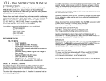
The ATX7006 is a modular system. In this section, the modules are described in detail.
The figure below represents a possible ATX7006, configuration.
The ATX has space for a maximum of 9 modules of various kind. The first available slot position is
assigned to the DIO module. The remaining slots are universal and can be assigned unrestrictedly.
3.1
Controller module
The controller module is a Windows-XP™ based controller unit that takes control over the ATX7006
specific backplane bus.
After switching on the ATX7006 with the backplane power switch, the Power supply starts up the
standby voltage. In standby mode, the Controller power switch LED lights up yellow. The ATX can
then be switched on by pressing the power switch. The power switch led then lights green. When the
power switch is pressed again the ATX shuts down and the power supply then switches over to
standby mode. Avoid switching off the system with the backside main switch when the ATX is
not in standby mode.
After power up, the controller starts the operating system and then starts the ATX7006 firmware
application. This application controls the modules in the system, handles all communication,
calculates stimulus signals and performs signal analysis calculations
Communication is established via GPIB (IEEE communication port) or Ethernet. To establish
communication using the Ethernet connector, the ATX can be connected to a local network . For a
direct communication link between a PC and the ATX, a crosslink Ethernet cable or optionally an
USB to Ethernet adapter can be used.
Page 9
ATX7006 user manual rev.2.10
3.1.1 Controller display and settings
Depending on the display settings, the touchscreen display shows the "Home" window giving status
information of the ATX, command interpretation and the installed modules.
The tabs on top of the window, lead to communication and display configuration settings. Selections
can be made using the touch screen, or a mouse.
To change the communication settings, select the communication tab and the communication
settings window opens. The GPIB communication can be enabled and the used GPIB address can be
configured . Alternatively, the commands GPIB_ADDR and GPIB_STATUS can be used for this.
The network configuration settings can be found in this tab.
Most network connections will be provided with a DHCP server. Select "Network with DHCP enabled".
This is the default setting.
If a static IP is required, or if a USB communication is preferred, the Standalone mode should be
selected. In that case, the IP address and subnet mask should be filled in at the “Advanced” tab.
Page 10
ATX7006 user manual rev.2.10
An example of a valid subnet is 255.255.255.0. This value should correspond with the subnet mask
on the client (pc) side. A valid IP address could be 192.168.2.2.
The corresponding commands for the network configuration are LAN_STATICIP, LAN_DHCP and
LAN_SUBNETMASK.
It is also possible to change the default port at which the ATX7006 is listening for incoming data, on
the “Advanced” tab. The corresponding command to change the port is LAN_PORT.
The “Display” tab allows to configure the display setup of the ATX7006.
When an external display is connected and selected to be used, the ATX7006 flat panel is disabled.
The touch screen calibration can also be started in this window. This calibration is to link the sensed
touch screen sensor coordinates to the right spot on the screen. The software of the touchscreen
interface "learns" which spots on the touch sensor overlay which spots on the screen.
3.1.2 Setup of USB communication
For USB communication with the ATX7006 system, a Network USB adapter is provided. Please
connect the USB cable to your PC and connect the network side with a cross link cable to the
ATX7006. The ATX7006 should be configured in Standalone/Static IP network mode (see description
above). On the pc side follow the next steps:
Go to Control Panel -> Network Connections and select the Local Area Connection of the
Sitecom USB to Ethernet adapter
Double click this icon select properties. Then select Internet Protocol (TCP/IP).
Page 11
ATX7006 user manual rev.2.10
Click on Properties and select "Use the following IP address:"
Fill in e.g. 192.168.2.3 for the IP address and 255.255.255.0 for the Subnet mask. The subnet
mask should correspond with the subnet mask on the ATX7006, while the IP address should
be different from the ATX7006 IP address .
Click on the Advanced button and select the tab WINS
At the NetBIOS settings, select the second item "Enable NetBIOS over TCP/IP “
Click Ok, again Ok and Close If the ATX7006 is configured with a static IP (e.g. 192.168.2.2)
Now, communication should be possible by using the IP address or NetBIOS name.
Page 12
ATX7006 user manual rev.2.10
3.1.3 Setting up ATX7006 communication in ATView7006/ATCom7006
Start ATView7006 and from the menu, select [Options][Communication settings]. Alternatively,
these settings can be configured in ATCom, using [File][Communication].
The configuration dialog opens:
Type the ATX NetBIOS name or IP address in the location field. The NetBIOS name can be found in
the upper-right corner of the ATX7006 controller display. On the ATX Express the NetBIOS name can
be found on the controller handle label.
Alternatively, the dialog can find all ATX systems in a specified workgroup. For this, specify the
workgroup name in the workgroup field and click find. (This will take some time). After this, the ATX
system can be selected from a list in the location field.
Optionally, the ATX server port can be specified. This port is set to 30111 by default.
Authentication is disabled by default on the ATX. Authentication can be configured using the
commands LAN_USER and LAN_ENABLEAUTH.
Press “Test” to check if communication settings are correct.
For GPIB communication settings, select the GPIB tab. In this tab, GPIB address and communication
timeout can be configured. Note that the entered GPIB address should correspond with the GPIB
address setting in the ATX. The GPIB address factory setting is address 4. To change this address,
use the command GPIB_ADDR. Alternatively, these settings can be changed using the ATX7006
touch screen, as described in section 3.1.1.
3.1.4 How to copy files to the ATX7006
For using the ATX commands EXECUTE_CMDFILE and EXECUTE_SCRIPT, the user needs to copy
the desired command file(s) or lua script file to the ATX system. For this, a connection should be
established for file transport. There are two possible ways to establish such a connection with the
ATX7006:
Network sharing
FTP connection
Network sharing
By default, the ATX7006 has network sharing for the userdata folder enabled. Please browse to the
workgroup ATX7006 (default) and select the ATX7006. A username and password is required to get
Page 13
ATX7006 user manual rev.2.10
access. The Network sharing username and password is a windows setting. The password and
username for network sharing is atx7006.
FTP connection
The ATX7006 has a build in ftp server. To start this server, refer to the command FTP (FTP START to
start the server listening on the default port 21). Again, the default start folder of the ftp server is
”userdata”. If the ATX7006 LAN communication is not protected with a specified username and
password, use the default username and password. The default Username is atx7006, the default
password is atx7006 as well. If the ATX7006 LAN communication is protected with a password,
please use the corresponding username and password.
LAN usernames and passwords are managed with the command LAN_USER.
file location.
As described above, the user file source directory is located on the ATX7006 system: c:/userdata.
When using a command or Lua file, a complete filename should be entered, including the file
extension and the path under the user data directory (excluding the folder name c:/userdata).
Example:
To run a command file named test.cmd, located in ATX folder c:\userdata\cmdfiles:
EXECUTE_CMDFILE cmdfiles\test.cmd
Page 14
ATX7006 user manual rev.2.10
3.2
Digital I/O module
The DIO module can operate in the following configurations:
Low speed mode (DIOLS)
In this mode, both capture and stimulus mode are supported. The data IO lines can be programmed
as input or output and can support up to 20-bit parallel or 24-bit serial formats. By default, the capture
and source memory depth is b 4M-words x 24bit. Using the DIO_IOMODE command, it is possible to
select a memory depth of 8M-words x16 bit. This option is supported from DIO FPGA revision 8
(see CID) and higher and firmware release 1.26 and higher.
The maximum data rate is 50MHz while the maximum Pattern Generator input clock frequency is
100MHz. The single ended IO levels are programmable to support 3.3V to 5V CMOS.
High speed (DIOHS) Capture mode
In the High speed capture mode, the DIO memory captures measurement data. The data width is
maximum 16-bits and is captured parallel on the SCSI connector. All inputs are operating in LVDS
format.
The measurement timing is controlled using delay lines. The maximum data rate is 200MHz.
High speed (DIOHS) Stimulus mode
In the High speed stimulus mode, the DIO memory holds stimulus data. The data width is maximum
16 bit and is applied parallel on the SCSI connector. All outputs are operating in LVDS format.
The measurement timing is controlled using delay lines. The maximum data rate is 200MHz.
By default, the DIO module starts in the DIOLS mode. When the operational mode is changed, the
module FPGA is reloaded automatically. Refer to the DIO_OPMODE command for more information.
DIO Front panel led
The DIO has one LED on the front panel, indicating the DIO status.
off
green
red
Module is in configuration mode.
Module is in measurement mode.
During power-up and at FPGA (re)load.
3.2.1 DIO Clock source board
Every DIO has an on board 200MHz crystal oscillator that generates a basic clock for the module.
Beside this oscillator, there is a clock source board.
On older DIO models this clock source board holds crystal oscillators of 120MHz, 140MHz , 160MHz
and 180MHz.
Newer DIO modules are equipped with a PLL clock generator board, which can generate virtually any
clock frequency between 2kHz to 945MHz. This PLL also emulates the legacy oscillator clock
sources, if they are selected.
The older modules can be recognized by their FPGA revision: in low speed mode, they have an
FPGA revision below 5, in high speed mode the FPGA revision is below 4.
The clock source can be selected with CCS. The PLL frequency can be set with DIO_PLL_FREQ.
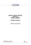
3.2.2 Digital I/O module in low speed mode
In low speed mode , the DIO module operates in a Pattern Generator based configuration.
The figure illustrates a simplified block diagram of the DIO in this configuration.
Pattern Generator
Page 15
ATX7006 user manual rev.2.10
The measurement timing is controlled by the programming of the Pattern Generator .
The timing of one sample consists of one pattern memory loop through a user defined part of the
pattern memory. The Pattern Bit memory depth is 256kWord.
The Pattern Generator runs at a maximum clock frequency of 100MHz, resulting in a 10ns timing
resolution.
The generator has 16 user programmable channels. Eight of those pattern channels are available to
the user as so called user Pattern Bits. The remaining bits are dedicated Pattern Bit channels, used
for internal synchronisation and IO data control. Two of those dedicated Pattern Bit channels are the
stimulus and capture-clock.
The Capture-clock is used to sample and store incoming (converted) data for the DIO in capture
mode and for all capturing (digitizing) modules in the system.
The Stimulus-clock is used to sample the outgoing DIO data, as well as being the sample clock for
all generator modules in the system. The capture-clock and stimulus-clock are provided through the
backplane to all module slots. The stimulus-clock is also available on the SCSI connector HSO pin.
For fine-tuning of the timing, additional programmable delay lines are put in the capture-clock and
stimulus-clock lines.
Clock sources
The Pattern Generator input clock is selected from a range of clock sources.
The PLL clock source board
Backplane Clock, Optionally sourced by one of the installed modules
An external clock source, connected to the front panel. The front clock input impedance is
50ohms, AC coupled and has a minimum input frequency of 1 MHz. The maximum input clock
frequency is 400MHz. The applied clock level may range from 200mVpp to 3.3Vpp .
Page 16
ATX7006 user manual rev.2.10
The Pattern Generator maximum input clock frequency of 100MHz. The mentioned clock sources can
therefore be divided by a factor 1,2,4 , 8 or 16 (for modules with clock source board), or 1..32 (for
modules with the PLL clock board).
In addition, HSI or a backplane clock can be chosen as clock source for the Pattern Generator. HSI is
an input line coming from the SCSI connector. The backplane clock can be driven by one of the
installed modules for synchronized timing with a distinct module clock frequency.
The PLL clock in its turn has a on board 10MHz oscillator reference. The 10MHz PLL clock reference
may also be applied externally, on the frontpanel . When an external clock is used as PLL reference,
the clock frequency should be 10Mhz.
Clock source selection is managed by the CCS command.
Note: DIO modules with FPGA revision lower than 5 are not equipped with a PLL board. A
revision check can be done using the CID command.
Trigger
Once the module is set in measurement mode, it waits for the trigger to be activated. By default, the
trigger is a software trigger, a bit set on receipt of the trigger command CTRIG_STATUS.
Alternatively, a trigger can be supplied from the front-panel and used to synchronize the start of the
pattern generation from an external source.
The level sensitivity is depending on the hardware- and FPGA revision.
For new FPGA revisions (5 or above for lowspeed mode, or 4 and above for highspeed mode), the
trigger input for the DIO is high sensitive.
For older FPGA revisions (below 5 for lowspeed mode, and belof 4 for highspeed mode), the trigger
input for the DIO is low sensitive.
The trigger input pin has an internal pulldown resistor, so leaving the input open sets the trigger input
low.
Pattern generator loop trigger
Optionally, the start of each pattern loop of the pattern generator can be controlled by a dedicated
pattern loop trigger pin, situated on the SCSI DIO connector pin 32. This is implemented to
synchronize the pattern generator loop with external signals, for example a “Conversion ready”
signal from a DUT. For more information, refer to the command PB_MODE.
Stimulus data generation and data capture
The capture/stimuli memory is 4 Mwordx24 bits. The maximum data rate is 50Mhz.
In stimulus mode, the StimClk from the Pattern Generator clocks the address counter. For data
generation, a user defined part of the memory is used. This way it is possible to store different
stimulus signals into different segments of the memory. The segment containing the stimulus data can
be repeated (looped) for settling purposes (Settle loops) or averaging purposes (Measurement
loops).
In capture mode, the CaptureClk increments the address counter. The captured data is stored in the
capture memory once the settle loops are finished (the settle loop counter has counted down to zero)
Generally, the number of measurement loops is one. Otherwise data of a preceding measurement
loop is overwritten.
Data control
The DIO supports the following IO modes for capturing or generation:
Parallel The maximum data width is 20 bit, limited by the number of available data IO pins
Byte by byte The maximum data width 2x 8bits
Serial data mode The maximum data width is 24 bits, limited by the memory word length.
The timing of the data IO is controlled with dedicated Pattern Bit channels.
IO levels
Page 17
ATX7006 user manual rev.2.10
The IO levels are adjustable, using the DIO_IOV command. They can be set to a voltage of 1.2 Volts
or to an adjustable voltage between 1.8 and 3.3 Volts (in ca. 256 steps). When the DIO operates in
capture mode, it is recommended to adjust the DIO IO level to the IO level applied.
Note: The level of the Pattern Bit channels goes along with the programmed IO level.
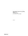
3.2.3 Digital I/O module in High speed capture mode
This high speed operation mode is set with DIO_OPMODE1 . The functional block diagram of the
High speed DIO has much in common with the low speed DIO diagram.
The data direction is now set to parallel input and all IO levels are differential LVDS.
The measurement timing is now derived from the clock source selection.
An on board PLL clock source with 10MHz PLL reference is available. Alternatively, the backplane
clock or an external clock source, connected to the front panel, can be used. The front clock input
impedance is 50 ohms, AC coupled and has a minimum input frequency of 1 MHz and a maximum
input clock frequency of 400MHz. The front clock may also be used as 10MHz reference clock source
for the PLL clock circuit.
Clock source selection is managed by the CCS command.
The mentioned clock sources can be divided with the Card Clock Divider (see CCLKDIV command)
by a factor 1, 2, 4, 8 or 16 (for modules with clock source board), or 1..32 (for modules with the PLL
clock board).
Note: DIO modules with FPGA revision lower than 5 are not equipped with a PLL board. A
revision check can be done using the CID command.
The Trigger signal, either being an external or a software trigger, enables the clock source
synchronously. The clock is split into three clocks, each timed with a delay line:
Page 18
ATX7006 user manual rev.2.10
- DUT Clock which is lead directly to the SCSI connector .
- CaptureClk which clocks the capturing module, in this case the DIO capture memory.
- StimClk which clocks the stimulus module, for example the AWG16 module.
The clock that leads to the DIO capture memory is also available on the SCSI connector as DCLK.
The timing relation between stimulus, capture and DUT clock can be adjusted by programming the
delay lines with DIO_CLKDELAY
3.2.4 Digital I/O module in High speed stimulus mode
This high speed operation mode is set with DIO_OPMODE2 . The functional block diagram of the
High speed stimulus mode has much in common with the previously described DIOHS capture mode.
The data direction is now set to parallel output and, again, all IO levels are differential LVDS. The
measurement timing is also derived from the selected card clock source, selected with CCS.
The same clock sources as described in the HSDIO capture mode are available.
The Trigger signal, either being an external or a software trigger, enables the clock source
synchronously. The clock is split into three clocks, each timed with a delay line:
The DUT clock and is lead directly to the SCSI connector.
CaptureClk which clocks the capturing module, for example the WFD16 module.
StimClk now clocks the DIO stimulus memory.
The stimulus clock that leads to the DIO memory is also available on the SCSI connector as DCLK.
The timing relation between stimulus, capture and DUT clock can be adjusted by programming the
delay lines with DIO_CLKDELAY
Page 19
ATX7006 user manual rev.2.10
3.3
AWG20 20-bit/2Msps Arbitrary Waveform Generator
The AWG20 module is a 20-bit, 2Msps Arbitrary Waveform Generator for medium speed / high
resolution waveform generation. The module has 8 output ranges to accommodate different DUT
input ranges.
Output voltage and available signal ranges
The output voltage swing is -10.24V to +10.24V for each output.
The output range (Signal voltage difference output relative to ground) can be set to : 0.08V, 0.16V,
0.32V, 0.64V, 1.28V, 2.56V, 5.12V, 10.24V (Vpp, single ended) . The differential output voltage
(between both outputs) is twice the programmed output voltage.
DC offset
The DC offset is added to the signal voltage by the DC offset DAC. The offset voltage range is from 5.12V to 5.12V , programmable in a 9,76uV resolution. The DC offset DAC is always connected to the
signal path. The voltage sensed on the ground sense input is added to the programmed offset voltage
to compensate for DC voltage loss over the ground connection.
The output voltage is composed as follows:
Voutpos Vsignal (Vdcbase Vgndsense )
Voutneg Vsignal (Vdcbase Vgndsense )
Voutpos
Voutneg
Vsignal
Vdcbase
Vgndsense
is the output voltage relative to ground on the positive force output.
is the output voltage relative to ground on the negative force output.
is the voltage programmed to the signal DAC, either by the CV command or the
stimulus.
is the voltage programmed to the dc offset DAC, either by the COV command.
is the voltage sensed on the GND sense input.
Page 20
ATX7006 user manual rev.2.10
Signal module selection
On board there are 4 signal module sockets. Each signal module can be equipped with 2 signal
conditioning functions.
By default, there is one signal module installed, containing two low pass filters to remove quantization
noise and improve THD at higher frequencies. This signal module carries the following filters:
1.2kHz Active 4-pole Butterworth low pass filter selected with command CPATH1
12kHz Active 4-pole Butterworth low pass filter selected with command CPATH2
40kHz Active 4-pole Butterworth low pass filter selected with command CPATH3
200kHz Active 4-pole Butterworth low pass filter selected with command CPATH4
The signal conditioning function of each signal path can be read and is set with CPATH_INFO
Placement of extra signal modules, up to a total of 4, is optional. Customized signal modules can be
designed for application specific purposes, to add extra ranges or specific filter types.
Alternatively, with command CPATH0, the signal can bypass the signal modules.
Connection options:
The switching of the gate relays can be configured with the CC command in the following ways:
1. Both outputs disconnected (CC0)
2. Differential, low impedance output with GND sense active (CC1)
3. Differential, 50 ohms output with GND sense active ( (CC2)
4. Differential, low impedance output with GND sense internally connected to AGND (CC3)
5. Differential, 50 ohms output with GND sense internally connected to AGND (CC4)
Clocks and trigger
The stimulus address counter is clocked either by the stimulus-clock coming from the backplane or by
an external clock. The backplane stimulus-clock is generated by the DIO module.
The clock applied will be used as sample clock and stimulus address counter clock and will not be
divided on this module. The applied clock frequency is equal to the sample frequency. The minimum
high time of the sample clock is 200ns.
The external clock can be connected to the backplane DIO clock line and can then be used as clock
source for the Pattern Generator. The clock can be switched to the backplane with parameter o of the
CCS command.
In most applications, a software trigger is used to start generation of the signal. Optionally, an external
trigger can be applied. An external trigger logic 3.3V TTL level sensitive. Trigger polarity (active low or
high) is for the external trigger programmable. Trigger source and polarity are defined with the CTRIG
command.
Latency counter
The clock to the signal memory counter is lead true a so called Latency Counter. Optionally, this
counter can be programed to create an additional clock latency, which can be seen as a user
configurable hold off counter. In normal AD converter measurements, it is not likely to use this
function, the Latency counter value should then kept to value 0. For other measurement setups, the
hold off feature may be useful.
Module auto calibration
For optimum accuracy performance, it is recommended to observe a warming-up period of at least
one hour after power up. The module auto calibration should be run at least every three months. An
auto calibration can be started with the command “CCAL_START” . The calibration time is dependent
of the number of available signal paths, and takes about 10 minutes plus 10 minutes for each signal
path. The auto-cal of an AWG module with 2 signal paths takes approximately 30 minutes. Refer to
Appendix B: Calibration procedure for details on the auto calibration sequence.
Front panel LEDs:
The front panel LEDs reflect the status of the module and the channel connection:
Page 21
ATX7006 user manual rev.2.10
The main module led:
off
Module is in configuration mode.
green Module is in measurement mode.
red
During initialization, self-test, auto-cal. Remains red after self-test error or
initialization error.
The Channel gate led (small led near the connector) :
off
Gate relays are open
green Gate relays are closed
red
Channel auto-cal active
3.4
AWG18 18 bit / 300Msps Arbitrary Waveform Generator
The AWG-18 module is a 18-bit, 300Msps Data update rate waveform generator, for high frequency
signal generation. In combination with a user selectable 2x or 4x or interpolation filter, the DAC is
capable of sampling at a frequency up to 1.2GHz. The maximum generated signal frequency is
150MHz, limited by the maximum 300Msps data rate. Interpolation reduces the influence of sinx/x at
high signal frequencies. The maximum DIO generated clock frequency is 200MHZ. For Sample
frequencies above 200MHz, an external clock should be applied.
Ranges
The following ranges can be set:
Range HF Path, (Vpp)
HF Path, (Vpp)
single ended
Differential
@50 Ohm load @100 Ohm
Differential load
0
4.63
3.28
1
3.28
2.32
2
2.32
1.64
3
1.64
1.16
4
1.16
0.82
5
0.82
0.58
6
0.58
0.41
7
0.41
0.29
LF path(Vpp)
Differential
@ No load
LF path(Vpp)
Differential
@50 Ohm load
6.55
4.64
3.28
2.32
1.64
1.16
0.82
0.58
3.28
2.32
1.64
1.16
0.82
0.58
0.41
0.29
Page 22
ATX7006 user manual rev.2.10
Output impedance
The output impedance of both Signal paths is 50 ohms. Therefore, signal amplitude is load
dependent.
When the HF path is used in differential output mode, a 100 Ohm differential load should be
connected between the outputs. In single ended mode, the P output should be loaded with a 50
ohms load. The P output is disconnected.
HF path
The HF path has a pass band of 10Mhz..100MHz and will not output DC. A differential or single
ended output configuration can be selected. In single ended output configuration, The P output is AC
coupled by means of an output capacitor, while the N output is open. In Differential output
configurations, the output is coupled by means of a single ended to differential HF transformer The
output transformer common is AC coupled to GND by means of a capacitor..
HF path Filters
The HF path has a filter bank containing 6 low pass filters. One Filter is optional an may be custom
specified . The installed filters are 7 pole elliptic low pass Filters with the following cutoff frequencies:
The “Signal path selection” section in this paragraph describes the filter selection.
LF path
The LF path has a pass band of DC..50Mhz.
The filter bank in the LF path consists of two 3-pole low pass filters with the following cutoff
frequencies.
15 MHz
30 MHz
To optimize noise performance in the lowest voltage , the range attenuator is situated close to the
output.
DC offset
The LF path has a separate DC offset dac for P and N output. This way it is possible to program two
different output offset levels on the output. An offset voltage can be set in the range from - 2.5V to
+2.5V , at no load condition. When the output is loaded with 50 ohms, the offset voltage is divided to
a range of -1.25V to +1.25V.
In the lowest ranges, (range 4,5 6 and 7) the output attenuator is switched in the signal path. In this
situation, the offset is also attenuated with a factor 12dB.
Signal path selection
As described, the board has an LF path and an HF path, each with a filter bank. The signal path is set
using CPATH command.
The following signal path configuration can be chosen:
LF signal path, Bypass filter: CPATH0
LF signal path through …MHz low pass filter CPATH1
LF signal path through …MHz low pass filter CPATH2
HF signal path, Bypass filter: CPATH10
HF signal path, through …MHz low pass filter : CPATH11
HF signal path, through …MHz low pass filter : CPATH12
HF signal path, through …MHz low pass filter : CPATH13
HF signal path, through …MHz low pass filter : CPATH14
HF signal path, through …MHz low pass filter : CPATH15
HF signal path, through …MHz low pass filter : CPATH16
HF signal path, through Custom pass filter : CPATH17, filter is not installed by default
The signal conditioning function of each signal path can be read and is set with CPATH_INFO
Page 23
ATX7006 user manual rev.2.10
In the HF path, placement of an extra Filter module is optional. Customized Filter modules may be
designed to replace the default filter for application specific purposes, to add specific filter types.
Connection options:
The switching of the gate relays can be configured with the CC command in the following ways:
1. Both outputs disconnected (CC0)
2. Differential, 50 ohms output (both HF and LF path) (CC1)
3. Single ended 50 ohms output (HF path only) (CC2)
Clocks and trigger
The stimulus address counter is clocked either by the stimulus-clock coming from the backplane or by
an external (user) clock. The backplane stimulus-clock is sourced by the DIO module.
The applied clock will be used as sample clock and stimulus address counter clock.
The applied clock can be divided internally up to a factor of 4 (CCLKDIV).
When external clock frequencies higher than 300MHz are applied, the clock to the stimulus memory
needs to be divided, because of the 300MHz maximum data rate limit. In this case, the converter
should be set to an interpolation mode. The command CINTERP is used to set the desired
interpolation mode :
CINTERP 1
CINTERP 2:
CINTERP 4:
(normal mode: fsample = fdata )
(fsample=2xfdata)
(fsample=4xfdata).
Where fsample is equal to the applied clock, divided by the setting of CCLKDIV
The product of the value set with CCLKDIV and the value set with CINTERP is limited by hardware
and has a maximum value of 4.
The possible combinations of CCLKDIV and CINTERP are:
CINTERP
1
1
1
1
2
2
4
CCLKDIV
DAC Sample
clock rate
DATA clock rate
DAC
DATA
Latency
Latency
(Fclk
(Fclk
periods)
periods)
1
Fclk
Fclk
128
TBD
2
Fclk/2
Fclk /2
256
TBD
3
Fclk/3
Fclk /3
128
TBD
4
Fclk /4
Fclk /4
384
TBD
1
Fclk
Fclk /2
216
TBD
2
Fclk /2
Fclk /4
432
TBD
1
Fclk
Fclk /4
376
TBD
Fclk is the module input clock frequency either from the front or from the DIO.
Total
Latency
(Fclk
periods)
TBD
TBD
TBD
TBD
TBD
TBD
TBD
The external trigger source cannot be used in combination with the internal sample clock.
The threshold levels of the trigger and clock source can be programmed to either 0V (for AC trigger or
clock sources) or to 1V for TTL compatible clock sources. The trigger is active when the level is higher
than the chosen threshold level.
Module latency and Initialization conversions
The latency of the module is dependent of the interpolation mode and clock divider setting . The Table
in the clocks and trigger section of this chapter shows the total latency according to the interpolation
and clock divider setting. After the measurement is started, it takes the total number of latency clock
cycles before the first digital sample can be measured at the analog output.
Page 24
ATX7006 user manual rev.2.10
Memory
The module contains a 8 M word stimulus memory. The stimulus memory array size must be a
multiple of eight.
Module auto calibration
For optimum performance, it is recommended to observe a warming-up period of at least one hour
after power up. The module auto calibration should be run at least every 3 months. An auto
calibration can be started with the command “CCAL_START”. Refer to Appendix B: Calibration
procedure for details on the auto calibration sequence.
Front panel LEDs:
The front panel LEDs reflect the status of the module and the channel connection:
The main module led:
off
Module is in configuration mode.
green Module is in measurement mode.
red
During initialization, self-test, auto-cal. Remains red after self-test error or initialization
error
The Channel gate led:
off
Gate relays are open
green Gate relays are closed
red
Channel auto-cal active
3.5
AWG16 16 bit / 200Msps Arbitrary Waveform Generator
The AWG-16 module is a 16-bit, 200Msps update rate Arbitrary Waveform Generator for high
frequency waveform generation.
Output voltage and available signal ranges
The output voltage range is -5.12V to +5.12V for each output.
The output signal range (Signal DAC voltage swing relative to ground) can be set to : 240mV, 320mV,
480mV, 640mV, 960mV, 1.28V 1.92V, 2.56V (Vp, single ended) The range is set with command
CRA. The differential output voltage (between both outputs) is twice the programmed output voltage.
Page 25
ATX7006 user manual rev.2.10
DC offset
The DC offset is added by a so called DC offset DAC. The voltage range is from -2.56V to 2.56V ,
programmable in a 78.125 uV resolution. The offset is always connected to the signal path.
The output voltage is composed as follows:
Voutpos V signal V dcbase
Voutneg V signal V dcbase
Voutpos is the output voltage relative to ground on the positive force output.
Voutneg is the output voltage relative to ground on the negative force output.
Vsignal is the voltage programmed to the 20 bit signal DAC, either by the CV command or the stimulus.
Vdcbase is the voltage programmed to the 20 bit dc offset DAC, either by the COV command.
Filter section
One of the three third order Butterworth low pass filters can be switched into the signal path .The
available filters have a cut off frequency of resp. 15MHz , 30MHz and 60MHz.
Clocks and trigger
The stimulus address counter is clocked either by the stimulus-clock coming from the backplane or by
an external (user) clock. The backplane stimulus-clock is sourced by the DIO module.
The clock will be used as sample clock and stimulus address counter clock and will not be divided on
this module. The applied clock frequency is equal to the sample frequency.
The external clock first leads through a clock-enable circuit. The trigger signal is synchronized with
the negative edge of the applied clock and then enables the passage of the clock signal to the clock
mux.
The external trigger source cannot be used in combination with the internal sample clock.
The threshold levels of the trigger and clock source can be programmed to either 0V (for AC trigger or
clock sources) or to 1V for TTL compatible clock sources. The trigger is active when the level is higher
than the chosen threshold level.
Initialization conversions
The DAC chip that is used on this module has a built-in self-calibrating feature. Each time the sample
clock is started, this self-calibration requires ca. 8500 clock cycles (and thus conversions) to reach it’s
optimum accuracy.
The latency of this module is 23. This means that after the measurement is started, it takes 23 clocks
before the first digital sample can be measured at the analog output.
Memory
The module contains a 8 M word stimulus memory. The stimulus memory array size must be a
multiple of eight.
Module auto calibration
For optimum performance, it is recommended to observe a warming-up period of at least one hour
after power up. The module auto calibration should be run at least every 3 months. An auto
calibration can be started with the command “CCAL_START” . Refer to Appendix B: Calibration
procedure for details on the auto calibration sequence.
Front panel LEDs:
The front panel LEDs reflect the status of the module and the channel connection:
Page 26
ATX7006 user manual rev.2.10
The main module led:
off
Module is in configuration mode.
green Module is in measurement mode.
red
During initialization, self-test, auto-cal. Remains red after self-test error or
initialization error
The Channel gate led:
off
Gate relays are open
green Gate relays are closed
red
Channel auto-cal active
Page 27
ATX7006 user manual rev.2.10
3.6
WFD20 20bit / 2Msps Waveform Digitizer
This module is a 20 bit Waveform Digitizer for medium-speed / high resolution waveform capturing
and analyzing. The module has a large number of configuration options. There are 8 input ranges to
choose from, which gives easy solutions for applying DUTs with various output voltages. A filter-bank
with 3 Low Pass filters provide signal conditioning options to obtain the best result in dynamic
performance: low noise and anti-aliasing. The special combination of four 18 bit ADCs to a 20 bit
converter gives an excellent SNR and linearity. With 4M-word (12M-byte) of memory a large number
of samples can be captured.
Input voltage and available input ranges
The common mode input voltage range is -10 to +10V for each input. The input range (voltage
difference over both inputs) can be set to : 0.544V, 0.816V, 1.36V, 2.04V, 2.72V, 4.08V, 5.44V, 8.16V
(Vpp)
DC offset DAC
Voltage range -5V to 5V programmable in a 9,54uV resolution. When used, the DC offset DAC
applies a common mode voltage to the - input of the input buffer. The DC voltage is not available on
the front connector. The DC offset DAC is connected, using the CC command.
filter selection
The following on board filters are available:
40kHz Active 4-pole Butterworth low pass filter
250kHz Passive 5-pole Butterworth low pass filter
800kHz Passive 6-pole elliptic low pass filter
Filter path selection is set with the CPATH command.
Connection options:
The switching of the gate relays can be configured with the CC command in the following ways:
n=0
Both inputs disconnected (gate relays open)
n=1
Single ended: +input connected, - input connected to AGND
n=2
Single ended: +input connected, - input connected to DC base DAC
n=3
Both inputs connected to front
n=4
Single ended: + to AGND , -input connected to front
n=5
Single ended: + to AGND , -input connected to DC offset DAC
n=6
Both inputs connected to AGND
Page 28
ATX7006 user manual rev.2.10
The input impedance for + and – input is 100Mohm typical, when connected.
Capture-clock timing
The maximum throughput rate of the module is 2Msps in Warp mode, and 1.5Msps in normal mode.
The operational mode is set with COPMODE.
For optimum performance it is recommended to program the falling edge of the capture-clock within
70ns after the rising Capture-clock edge. A minimum clock high time of 20ns should be observed.
Alternatively, the capture-clock high time can be programmed to at least 385ns in Warp mode or to
520ns in normal mode.
In Warp mode, the time between conversions should not exceed 1ms.
Clock source selection
The memory address counter is clocked either by the Capture-clock coming from the backplane or by
an external clock. The backplane Capture is generated by the DIO module. The chosen clock will not
be divided on this module.
The external clock may be connected to the backplane DIO clock line and can then be used as clock
source for the Pattern Generator. The clock can be switched to the backplane with parameter o of the
CCS command.
Module auto calibration
A module auto calibration should be run at least every 3 months. For optimum accuracy
performance, it is recommended to observe a warming-up period of at least one hour after power up.
An auto calibration can be started with the command “CCAL_START” and takes approximately two
minutes. Refer to Appendix B: Calibration procedure for details on the auto calibration sequence.
Front panel LEDs:
The front panel LEDs reflect the status of the module and the channel connection:
The main module led:
off
Module is in configuration mode.
green Module is in measurement mode.
red
During initialization, self-test, auto-cal. Remains red after self-test error or
initialization error
The Channel gate led (small led near the connector) :
off
Gate relays are open
green Gate relays are closed
Page 29
ATX7006 user manual rev.2.10
3.7
WFD16 16-bit / 180Msps Waveform Digitizer
The WFD16 module is a 16-bit, up to 180Msps sample rate Waveform Digitizer for high frequency
waveform digitizing.
Input and signal ranges
The common mode input voltage range is dependent of the chosen signal range.
Common mode input voltage range
+/- 7.12 Vdc
+/- 5.70 Vdc
+/- 3.56 Vdc
+/- 2.85 Vdc
+/- 1.78 Vdc
+/- 1.42 Vdc
+/- 0.89 Vdc
+/- 0.71 Vdc
3.84 Vp
3.072 Vp
1.92 Vp
1.536 Vp
0.96 Vp
0.768 Vp
0.48 Vp
0.384 Vp
Ranges
2.56 Vp
2.048 Vp
1.28 Vp
1.024 Vp
0.64 Vp
0.512 Vp
0.32 Vp
0.256 Vp
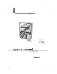
The input range can be set with the CRA command
The voltage difference between the inputs can be +/- the given input range in Vp.
Example:
The figure shows the possible maximum signal amplitude for the chosen range of 2.56 Vp
Page 30
ATX7006 user manual rev.2.10
Filter section
One of the three third order Butterworth low pass filters can be switched into the input signal path.
The available filters have a cut off frequency of resp. 15 MHz , 30MHz and 60MHz It is possible to
bypass the filters. Refer to the CPATH command for filter path selection.
Input configurations and DC offset DAC.
The connection of each input can be set, independent from each other, to one of the following input
configurations:
+ or – input configurations
-0-1-2-3-4-5-6-
Open
50 ohms input impedance, DC coupled input
50 ohms input impedance, AC coupled input
Buffered input, input impedance is 10k ohms, DC coupled
Buffered input, input impedance is 10k ohms, DC coupled
Input connected to DC offset DAC (input connector floats)
Internally connected to AGND (input connector floats)
The CC command has therefore two connection parameters n and o. Parameter n for selecting the
connection of the positive input, parameter o for selecting the connection of the negative input.
When only one parameter (n) is defined, both inputs are connected in the same configuration:
Examples:
CC1 : Both inputs 50 Ohms DC coupled. It has the same meaning as CC1,1.
CC2,5 Positive input AC coupled 50 ohms input impedance.
Negative input connected to DC offset DAC
CC0
Both gate relays open, inputs disconnected.
The DC offset DAC is a 16 bit DAC that can be programmed from -2.56V to +2.56 Volts.
A differential input can be set by setting both inputs to the same input connection number, 1 to 4
The module is connected in a single ended configuration when one of the two inputs is set to
connection number 5 or 6.
The command is used to connect the AWG16 inputs as desired.
Clocks and trigger
The address counter is clocked either by the capture-clock coming from the backplane or by an
external (user) clock. The backplane capture-clock is sourced by the DIO module.
The clock will be used as the sample clock and capture memory address counter clock and will not be
divided on this module. The applied clock frequency is equal to the sample frequency.
The external clock first leads through a clock-enable circuit. The trigger signal is synchronized with
the negative edge of the applied clock and then enables the passage of the clock signal to the clock
mux. The trigger is pulled high, so when not connected the trigger is active.
The external trigger source cannot be used in combination with the internal sample clock.
The threshold levels of the trigger and clock source can be programmed to either 0V (for AC trigger or
clock sources) or to 1V for TTL compatible clock sources. The trigger is active when the level is higher
than the chosen threshold level.
Memory
The module contains a 8 M word capture memory.
The capture memory array size must be a multiple of two.
Page 31
ATX7006 user manual rev.2.10
Module auto calibration
For optimum performance, it is recommended to observe a warming-up period of at least one hour
after power up. The module auto calibration should be run at least every 3 months. An auto
calibration can be started with the command “CCAL_START” . The auto-cal of the WFD module takes
approx 100 seconds. Refer to Appendix B: Calibration procedure for details on the auto calibration
sequence.
Front panel LEDs:
The front panel LEDs reflect the status of the module and the channel connection:
The main module led:
off
Module is in configuration mode.
green Module is in measurement mode.
red
During initialization, self test, auto cal. Remains red after self test error or
initialization error
The Channel gate led:
off
Gate relays are open
green Gate relays are closed
red
Channel auto cal active
Page 32
ATX7006 user manual rev.2.10
3.8
Dual reference Source module (DRS)
The Dual Reference Source module consists of two independent channels, each providing a
programmable voltage ranging from -10 Volts to +10 Volts. The output of the DAC is monitored by an
ADC which adjusts the output voltage more accurate. The result is a 20-bit equivalent DAC.
The ADC resolution is dependent on the selected A/D update rate. The output settling time is
therefore dependent of this accuracy.
The figure below shows how the output voltage settles to the programmed output voltage (Vp) when
the module is in controlled mode.
The loop controller calculates the DAC codes belonging to the programmed output voltage. The DAC
is programmed with this code and the output voltage is then sampled again. From this sample a
correction is calculated and the DAC is programmed again. Taking a sample and calculating a
correction code occurs with one control-loop time tc. For the most part, tc is determined by the A/D
resolution setting.
Typically, the output voltage steps toward the programmed output voltage within 2 or 3 times tc. When
the ADC reads an output voltage that's within a certain area from the programmed output voltage, the
output voltage is considered to be settled.
Page 33
ATX7006 user manual rev.2.10
As long as the output voltage is within this settle area, the output voltage can be corrected by the loop
controller with 0,3uV max. (Vcm) within one tc. However, when the absolute difference between the
ADC reading and the programmed output voltage is greater than the defined settle area, the controller
calculates a new correction value, resulting in a larger correction glitch.
The faster the ADC is running, the ADC results get more noisy, increasing the chance on such a
correction glitch. To minimize correction glitch occurrences, a higher ADC resolution can be chosen.
The drawback is longer settling time. Alternatively, a larger settled area can be programmed, the
drawback of this is that the "settled" output voltage can deviate more from the desired voltage.
The resolution can be changed with the "DRS20_RES" command.
DRS20 resolution setting
setting n
ADC ENOBs
0
1
2
3
4
5
6
7
24.4
24
23.5
22.9
22.5
22
21.6
21.2
approx Ts for 5V swing
within +/-43uV
338
146
75
40
21
13
8
NA
The settle area is programmed with command "DRS20_SETTLEAREA" and is actually the max
difference in ADC code reading and the ADC code reading that corresponds to the programmed
output voltage. One ADC code is approx 2.7uV. The default settled area is set to 16 this corresponds
to 16x +/-2.7uV = +/- 43uV .
After settling to the programmed voltage, it is possible to switch off the ADC controlled mode and put
the channel in static mode. This is to eliminates the occurrence of correction glitches on the output
voltage. This can be done with the "COPMODE" command.
The ADC of the loop controller can also be used as a voltmeter. The ADC input is switched between
the sense lines and measures the voltage difference. The voltage on the negative sense line is
clamped to AGND by two diodes. Therefore, the voltage level on the GND sense should be within +/0.6V from AGND. The input voltage range on the positive sense input ranges from -10V to +10V.
For a voltage measurement a special connection mode is implemented. Use command CC3 to
connect the sense lines only. Internally, this command connects the ADC input mux to the sense lines
and disconnects the sense line from the reference four wire buffer circuit.
DRS20_MV? DRS20 single voltage measurement.
n = expected voltage
Page 34
ATX7006 user manual rev.2.10
The fixed 7.2V Reference voltage on the module is an ultra-stable, temperature controlled reference.
It is used for the module itself, but also as a calibration reference for other modules within the system
via the backplane connector. To calibrate the ATX7006, the exact output voltage of this fixed
reference should be measured and stored as a calibration parameter. This voltage is available on the
SMB connector, situated on the DRS front panel.
There is also a possibility to connect the output of channel 1 to the backplane as calibration reference.
Refer to Appendix B: Calibration procedure for a calibration procedure description
Module auto calibration
For optimum accuracy performance of the reference module, it is recommended to perform a module
auto cal regularly Auto calibration should definitely be run approximately one hour after power
up. An auto calibration can be started with the command “CCAL_START”. Auto calibration of the
reference module takes approximately five seconds.
Test board filtering
The reference output may be filtered near the devices reference connection. The maximum
recommended capacitive load for a reference channel is 10uF. Larger capacitive loads may result in
slow sense circuit responses. An additional filter may be used to suppress broadband noise. A simple
RC network works fine for high impedance reference inputs. When the reference current is resistive
and changes dynamically with converter code, an additional post-filter opamp buffer can be used as
low impedance reference voltage driver.
Connection options
Each channel output of the DRS has a buffer amplifier circuit with Kelvin inputs. The load can be
connected using a 4-wire or 2-wire connection. With a 4-wire connection, the sense lines should be
connected to the force lines near the load.
The voltage difference between force and accompanying sense lines should not exceed 0.6 Volts.
The sense lines are clamped with two diodes.
From 0.6V voltage difference, current starts to run through the clamping diodes, resulting in an output
voltage error. Every nano Ampere of input clamping current results in at least 1uV output voltage
error.
Page 35
ATX7006 user manual rev.2.10
In two-wire connection mode, the sense lines are connected internally. The sense pins on the
connector can remain unconnected.
Front panel LEDs
The front panel LEDs reflect the status of the module and the channel connection:
The main module led:
off
controlled mode is off
red
During initialization, self-test, auto-cal. Remains red after self-test error or
initialization error.
The Channel gate led (small led near the connector) :
off
Gate relays are open
green Gate relays are closed (two or 4 wire)
red
Channel auto cal active
Page 36
ATX7006 user manual rev.2.10
3.9
Dual Power Supply module (DPS)
The DPS module is a 2 channel power supply with a programmable output voltage range of +/- 12V
at a maximum load of 200mA for each channel. In addition, the current and voltage at the output can
be monitored.
DAC
The channel output voltage range is +/-12V, programmable in steps of 371uV. For PSRR
measurements it is possible to generate a modulated voltage. For this purpose, the control block has
a stimulus memory of 8ksamples for each channel. To use the stimulus function, the module should
be set in measurement mode. The sample clock used for the stimulus function is derived from an on
board 1MHz clock source. By means of a clock divider, programmed with, CCLKDIV, the sample
clock frequency can be set between 1Hz and 1MHz. The stimulus starts when set in measurement
mode and after receiving a channel dedicated software trigger. Due to the limited 1.1kHz bandwidth of
a DPS channel, fast transients may be programmed but will not appear on the output voltage.
Output driver voltage and current limit
To minimize dissipation the output driver supply voltage is internally switched to +/-7.5V or +/-15V,
dependent on the voltage programmed to the channel. The output voltage is automatically switched to
15V for output voltages greater than 5.5 Volts. The maximum dissipation is approx 2W, which in
normal operation, is the case if the output voltage is set to 5.50 volts. The voltage drop over the driver
is then 9.5Volts. At a load current of 200mA, the driver dissipates 1.9Watts.
Each output has a programmable current limit so each channel can be used as programmable
current source. This limit can be programmed between 10mA and 200mA in 0,22mA steps. The
current limit is set to 200mA by default. When the current limit is reached, the channel gate LED will
light up red.
A maximum output driver dissipation of 2W should be taken in account when setting the current limit and
the card output voltage. When the output voltage drops due to the current limit, the voltage over the
output driver increases. When expected output voltage is lower than 5.5 volts, it is recommended to
Page 37
ATX7006 user manual rev.2.10
force the driver supply voltage to 7.5V to decrease the dissipation. This is done by programming the
DAC to an output voltage lower than 5.5 Volts.
To calculate the dissipated power :
Pdissipatio n U driver I lim it
The voltage across the driver is equal to the Driver supply voltage minus the Channel output voltage.
U driver U sup ply U out
U out I limit * Rload
U sup ply 15V @ CV 5.50Volts; 7.5V @ CV 5.5Volts
So, when the DAC is set to a voltage >=5.5V
Pdissipation (15 U out ) I limit 15 I limit I limit * Rload
2
When the DAC is set to a voltage <5.5V:
Pdissipation (7.5 U out ) I limit 7.5 I limit I limit * Rload
2
When the output driver dissipation is too high, the driver can overheat and the internal thermal
shutdown circuit activates. The output driver is then shut down and all relays, of both channels are
disconnected. The module cannot be used until the thermal conditions are normal again and
the status register of the channel is reset. (refer to the command DPS16_STATUS command
description) The current limit and the over temperature status can also be read from a status register
with this command.
The current limit circuit is sensitive to abrupt and fast short circuit conditions. The parasitic elements
of the interconnect lead inductances between the output amplifier and the load can cause significant
transient voltage spikes over the current sensing circuit which can lead to polarity reversal from
sourcing current limit to sinking and vice versa. In some cases, this can cause the current limit circuit
to go to the incorrect current limit direction and hang up. To prevent such situations it is highly
recommended to avoid hot switching.
Should the current limit circuit come in this condition, then use the following command sequence to
solve the current limit hang up:
CV0;CC0; program the output voltage to 0Volts, disconnect the module
DPS16_CL10 ; program the current limit to the minimum current limit of 10mA
DPS16_CL200 ; program the current limiter back to the desired value.
Current and voltage monitoring
Each channel has a 16bit ADC converter to monitor the actual Voltage and current at the channel
output. The resolution is 372uV and 7,6uA respectively.
To monitor DPS channel load current or actual output voltage, the command DPS16_MCor
DPS16_MVcan be used.
The measured output voltage on the DPS channel can differ from the programmed output voltage
when the channel output current has reached the selected current limit.
Additionally, the ATX system supply currents can be monitored using the PS_CURRENT command.
This is to prevent an overload situation of the system supply voltages.
The current rating of the +/-8 volts system supply is 2 ampere in total. This supply voltage is used for
DPS output voltages programmed beneath 5.5 volts.
Page 38
ATX7006 user manual rev.2.10
The current rating of the +/-15 volts System supply is 1.5 ampere in total. This supply voltage is used
for DPS output voltages programmed above 5.5 volts;
Connection options:
Each channel output of the DPS has a buffer amplifier circuit with Kelvin inputs. The load can be
connected to the load using a 4 wire or 2 wire connection.
With a 4 wire connection, the sense lines should be connected to the force lines near the load. In two
wire connection mode, the sense lines can remain unconnected. They are connected in the module
internally.
Front panel leds:
The front panel leds reflect the status of the module and the channel connection:
The main module led:
off
Module is not in measurement mode (CMODE command)
green Module is in measurement mode
red
Module performs auto-cal, self-test or module has self-test error
The Channel gate led (small led near the connector) :
off
Gate relays are open
green Gate relays are closed (two or 4 wire)
red
Channel is in current limit Channel or auto-cal active
Page 39
ATX7006 user manual rev.2.10
3.10 ATX7006 power supply
The power supply of the ATX7006 system consists of a switching and a linear section.
The switching supply provides the controller module and digital section of the modules. The linear
section provides the Analog section of the modules.
On/off switching
The main power switch is situated on the ATX7006 Back panel. When switched on, the digital supply
starts up the standby supply voltage. The controller power switch-led lights up yellow. The primary
part of the analog supply also switches on, but the regulator circuitry is disabled. When the power
switch on the controller module is pressed, the ATX supply switches over from standby to on. All
digital and analog supplies are switched on and the fans start to run. The controller power switch-led
then lights up green. The ATX starts up the operating system and the application software. Switching
off the ATX7006 with the backside main power switch while the ATX is not in standby mode
should be prevented. To shut down, first press the front power button. The operating system is shut
down and then the power supply switches back to “stand-by”. After this, the power supply main switch
can be switched off.
The supply current can optionally be monitored by means of the command PS_CURRENT.
Mains selector (110-240V Mains voltage)
The factory setting of the mains selector is the 240V, unless agreed
otherwise. For a mains voltage of 110-120V, the mains selector should
be switched to “120” using an average-size blade screwdriver. The fuse
rating should correspond to the mains voltage selected.
Caution: Always operate the ATX7006 with the correct mains
voltage. A mains voltage higher than selected with the mains
selector may result in damage to the ATX.
Fuse replacement (110-240V Mains voltage )
The fuse should always be replaced with the same type and value.
The replacement fuse should be of a Antisurge (T) 20mm x 5mm
Ceramic type . The current rating is dependent of the mains voltage
selected:
220-240V:
2.5A
110-120V:
5A
100V Mains supply
In case of a 100V mains supply, the mains voltage should be at least
96V.The maximum allowed mains voltage is 110V. Operation with
incorrect mains voltage will result in damage to the ATX7006.
At the Power entry, a second fuse holder is situated at the mains selector
position.
The fuses should always be replaced with the same type and value.
The replacement fuse should be of a Antisurge (T) 20mm x 5mm
Ceramic type . For a 100V mains voltage, the current rating is :
Left fuse:
2.5A (Analog supply)*
Right fuse:
2.5A (Digital supply)
2
*The fuse should have a minimum I t value of 14. Recommended
Fusetype is Littlefuse 213 series with “Time lag surge withstand”.
Page 40
ATX7006 user manual rev.2.10
4 Measurement set-up
This section describes in detail how to setup a measurement and the result calculations using the
ATX7006 commands.
When ATVIEW is used to setup a measurement, a command set is generated automatically. ATVIEW
performs the measurement and calculates the result.
Using ATVIEW, a detailed knowledge of the command structure is not needed. However, to get a
clear vision about the operation of the ATX7006 system it is useful to take notice of the commands
needed to setup a measurement. When the system operates without ATVIEW , for example in an
ATE environment, it is necessary to know the details of measurement setup and calculation settings
needed to retrieve the desired measurement results.
Generally, a measurement consists of the following steps:
-Setup the stimulus generator and capture memory
-Select and define a stimulus signal.
-Program the signal definition into a module stimulus memory
-Setup the stimulus address counters
-Setup of stimulus loop and latency counters
-Setup the capture memory address counters
-Setup of capture loop and latency counters
-Measurement timing and static IO setup
-Setup the measurement timing with the Pattern Bit definition
-Setup static output lines
-Initialize and connect module channels
-Initialize and connect reference and power supply channels
-Connect the used generator or capturing modules
-Start the measurement
Post measurement steps
After the measurement, the following steps can be taken:
-Calculation-parameter and -options definition
-Start calculation
-Read out measurement and calculation results
Note: By default, calculation of parameters is not supported in ATX-Express systems.
4.1
Setup the stimulus generator
A stimulus generator is the digital part in a module that generates the test signal. It consists of a
memory and an address counter. The address counter is initiated with the address that holds the first
sample. During the test the address counter is incremented on each cycle of a stimulus-clock. At the
end of the stimulus signal definition, the address counter is reloaded with the start address. This way
the stimulus can be looped.
The stimulus signal can either be digital (digital IO module in stimulus mode) or analog (waveform
generator module) In this section, the setup of this stimulus generator is discussed.
4.1.1 Defining a Stimulus signal
One complete stimulus signal definition is called a signal item. It is possible to define up to 10
different signal items. This makes it easy to change a stimulus signal or to load different signals in
different modules or even on different locations in one stimulus memory. This option reduces memory
load time when switching of stimulus signals is desired.
Page 41
ATX7006 user manual rev.2.10
The stimulus signal form in the signal item is a result of a summation of one or more signal
definitions. Depending on the measurement type, a signal definition can contain a ramp, a sine, a
triangle, or a square wave.
The figure shows the sequence to define one or more signal items and load them in one or more
modules.
First, the signal item to store one or signal definitions in should be selected with SIGNAL_SELECT. A
maximum of ten different signal items can be programmed.
Next, the signal definition(s) can be stored in the signal item, using the SIGNAL and SIGNAL_ADD
command. A signal definition is a collection of parameters that define the type of signal, and
accompanying signal properties like amplitude, phase, number of samples, etc.
SIGNAL(_ADD) n,o,p,q[,r,s,t] Define signal
n = signal type:
n=0
n=10
n=1
n=11
n=2
n=12
Digital ramp defined by endpoints and number of steps
Analog ramp defined by endpoints and number of steps
o = start value of ramp
p = end value of ramp
q = number of ramp steps
r = settle steps, placed at the start of the ramp (default value=0)
s = repeat (total number of repetitions of the ramps in this definition)c
Digital ramp defined by start point, increments and number of steps
Analog ramp defined by start point, increments and number of steps
o = start value of ramp
p = increment value
q = number of ramp steps
r = settle conversions, placed at the start of the ramp (default value=0)
s = repeat (total number of the ramps in this definition)
Digital sine wave
Analog sine wave
o = amplitude (peak)
p = offset
q = number of samples
r = periods (default 1)
s = phase (degrees, default 0)
Page 42
ATX7006 user manual rev.2.10
SIGNAL(_ADD) n,o,p,q[,r,s,t] Define signal
(continued )
n = signal type:
n=3
n=13
n=4
n=14
n=5
n=15
n=6
n=16
Digital triangle wave
Analog triangle wave
Digital square
Analog square
o = amplitude (peak)
p = offset
q = number of samples
r = periods (default 1)
s = phase (degrees, default 0)
t = symmetry (%, 0..100, default 50)
digital from file
analog from file
o=filename(on the Atx7006 system) each sample should end with LF
digital custom
analog custom
o= add sample or multiple sample separated by comma
A digital value for increment, amplitude offset is right oriented, the card driver recalculates the signal
(i.e. digital shift) for the appropriate module.
To load the stimulus signal into the stimulus memory, the target module should first be selected. The
actual stimulus signal is calculated and stored with the CMF command. Optionally, the start address
of the stimulus signal can be assigned. This way, more than one signal can be stored into one
stimulus memory to eliminate memory load time during tests.
The resulting stimulus signal after the CMF command is executed, is a summation of signals defined
in a signal item.
For analog signal definitions, this summation results in a stimulus signal with an amplitude that is
clipped at value 0.0 and 1.0. Value 0.0 corresponds to the minimum scale and 1.0 corresponds to
the maximum scale of the stimulus signal DAC.
In fact, an analog signal definition results in a multiplier , that is multiplied with the output range of the
DAC.
The frequency of a signal is determined by the total number of samples or array size (q) ,the number
of periods (r) and the sample frequency fsample
f sig
f sample periods
arraysize
f sample r
q
r
or
q t sample
or
f signal q t sample
Alternatively, the number of periods can calculated with:
periods(r )
f signal arraysize
f sample
f signal q
f sample
The use of the signal definition command is best described following some examples.
Page 43
ATX7006 user manual rev.2.10
example 1:
Desired output signal: sine wave 6Vpp, 1kHz, fsamp=500kHz generated with the AWG20
module in 65536 samples.
The desired output stimulus signal is a sine wave 6Vpp, centred in the output range of the signal
Waveform generator signal DAC. Note that the DC offset DAC adds an extra offset, independent from
the signal definition. The value of the DC offset DAC is therefore disregarded in this example. There is
only one harmonic, so only one signal definition should be entered for this signal item.
The generating module is a AWG20, set in the 10.24Vpp range.
In the sine definition, the amplitude is defined in Volts peak. The desired peak amplitude of a 6Vpp
sine wave is 3V.
The amplitude parameter o for the signal definition is calculated :
o
desiredAmplitude(Vp ) 0.5 Amplitude (Vpp)
DACrange
DACrange
o
3(Vp )
0.29296875
10 .24
The offset parameter p:
Offset(Vo)
;[0 p 1]
DACrange
Offset(Vo)
0V
p 0.5
0.5
DACrange
10 .24V
p 0.5
The frequency of the sine wave is determined by the total number of samples (q) ,the number of
periods (r) and the sample frequency.
f sig
r
q t sample
To get a 1kHz sine wave with a sample freq. of 500kHz (tsample=2us) using 65536 samples the number
of periods can be calculated:
r f sig q t sample 1 10 3 65536 2 10 6 131
When defining a sine wave, it is best to choose a prime number of periods. 131 happens to be a
prime number. Otherwise, r could be replaced with the nearest prime number resulting in a slightly
different signal frequency.
The signal definition parameters are now put together in the Signal command:
signal12,0.29296875,0.5,65536,131
Page 44
ATX7006 user manual rev.2.10
example 2:
Desired signal definition should be stored in signalitem1:
Sine wave with amplitude Vpp 60% of full scale around midscale, 1kHz,
added sine wave of 10% of full scale, 10kHz
fsamp=500kHz generated with the AWG20 module in 65536 samples.
first, select the signal item to be edited:
SIGNAL_SELECT1
Then define the signal parameters for the 1kHz sine:
SIGNALn,o,p,q,r
n=12 for analog sine
o=0,3 (amplitude peak is 30% of full scale)
p=0,5 (sine should be located around halve)
q=65536 (number of samples)
r=131 (131 periods in 65536 samples and fs=500khz result in 0.99945kHz )
SIGNAL12,0.3,0.5, ,65536,131
Then define the signal parameters for the 10kHz sine:
SIGNAL_ADDn,o,p,q,r
n=12 for analog sine
o=0,05 (amplitude peak is 5% of full scale)
p=0 (no additional offset to keep the resulting signal around midscale)
q=65536 (number of samples)
r=1307 (1307 periods in 65536 samples and fs=500khz result in 9.97162kHz )
SIGNAL_ADD12,0.05,0, 65536,1307
SIGNAL? now returns the two signal definitions in signalitem1:
12,0.300000,0.500000,65536,131,0.000000
12,0.050000,0.000000,65536,1307,0.000000
Page 45
ATX7006 user manual rev.2.10
example 3:
What happens if the 1kHz sine has an amplitude of 90% of full scale and the 10Khz sine keeps
the same amplitude of 20%pp of full scale
Like in example 2, we define the two sine waves:
SIGNAL12,0.45,0.5, 65536,131
(90%pp amplitude)
SIGNAL_ADD12,0.10,0,65536,1307 (20%pp amplitude)
The signal definition will result in a signal item positioned around midscale with a theoretical
amplitude of 110% of full scale. As expected, the signal is clipped at value 0 and 1:
example 4:
Definition of a digital ramp stimulus that steps from code 0 to code 0xF in 16 steps. The
desired number of ramps in the stimulus is 2 with 5 settle conversions )in between the ramps.
SIGNAL0,0x0,0x0F,0x10,5,2 (SIGNAL0=digital ramp defined by start and endpoint)
0x10 is the total number of ramp steps excluding the settle conversions
OR
SIGNAL1,0x0,1,0x10,5,2
(SIGNAL1=digital ramp defined by startpoint and increment)
0x10 is the total number of ramp steps excluding the settle conversions
When this signal item is stored into memory it results in the following stimulus:
Page 46
ATX7006 user manual rev.2.10
4.1.2 Programming a signal definition into a stimulus memory
To program one of the 9 signal items into the selected module memory, the CMF command can be
used.
CMF[n,o,p]
n is the signal item,
o is the memory offset address.
p is the number of logical shifts applied to the data before storage.
In case of an analog signal definition, the CMF command converts the analog definition with values
ranging between 0 and 1 into the module's digital domain. In case of a 20 bit module, an analog
sample of value 1 is converted in a 20 bit value 3FFFFhex.
An offset address can be specified. This defines the start address of the storage location in the
stimulus memory. This way it is possible to store more than just one signal item into one module
memory. By default, this offset address is 0.
When needed, the digital codes written to the stimulus memory can be logically shifted with shift
parameter p. For a left shift (least significant bits are loaded with 0) a negative shift value should be
given. This feature can be used for (serial) DA converters that do not use the least significant bits of
the applied data.
If for example p = -2, a digital ramp with codes, 0,0x1,0x2,0x3,0x4,0x5.. etc. is stored into the
memory as 0x0,0x4,0xB,0xC,0x10,0x14.. etc.
Example:
To store signalitem0 into card0 from memory address 0:
send command 0CMF : the default values for n and o are used, 0CMF0,0 has the same result
To store signalitem0 into card6 from memory address 800hex:
send command 6CMF0,0x800
To store signalitem2 into card2 from memory address 400hex:
send command 2CMF2,0x400
Once a stimulus signal is stored, it is possible to read back the signal from the module memory with
the command CSIGNALDn,o (card signal dump), n is the start address, o is the number of samples to
dump.
In case of an analog module, this command returns the actual voltage values that correspond with the
stored hexadecimal values.
In case of a digital module, this command returns the contents of the memory in hexadecimal format.
Page 47
ATX7006 user manual rev.2.10
4.1.3 Setup the stimulus address counters
The stimulus is now loaded into the stimulus memory. Now, the stimulus address counter should be
initiated , normally to the "return-to" address which is the start of the stimulus signal. The command
"CMEMA" writes this start address directly to the stimulus counter.
The "return to" and "end" address pointers of the stimulus should also be defined. The return to
address is the address that is loaded into the address counter when the end of the stimulus is
reached.
The end address defines the position of the last sample of the stimulus . When the address counter
reaches this address, it is reloaded with the defined "return to" address.
The stimulus return to address is defined with the command CMEM_RET
The stimulus end address is defined with CMEM_END
In the figure, the address counter is initiated to the address holding sample data # -3.
The memory return address is set to the address holding sample data #0, while the end address is
set to the address holding sample data #130.
When the measurement starts, data# -3..data# -1 will be part of the stimulus only once. When the
address pointer reaches the cmem_end pointer, the address counter returns to the CMEM_RET
pointer situated at sample #0
In most situations, the address counter "CMEMA" will be initiated with the "CMEM_RET" address.
NOTE1: the end address is always one smaller than the number of stimulus steps.
NOTE2: In case of a ramp signal, the number of stimulus steps is the sum of settle
conversions and ramp step.
CMEM_END= CMEM_RET + (Stimulussteps-1)
Example:
The stimulus signal is situated between stimulus address 0X1000 and stimulus address 0x2000
The module that generates the stimulus is the AWG20 module on card location 2.
CSELECT2; select card location2
CMEMA0x1000 ; initiates the address counter to the start address
CMEM_RET0x1000 ; sets the return to address to address 0x1000
CMEM_END0x2000 ; sets the stimulus end address to address 0x2000
Page 48
ATX7006 user manual rev.2.10
4.1.4 Setup of stimulus loop and latency counters
The idea behind settle loops is that a stimulus signal is applied ("looped") a number of times before
the actual capturing starts. Settle loops can be programmed to let filters on the test board settle .
During a measurement loop, the capturing module captures and stores the converted results.
In the generating module, the length of one loop is determined by the number of samples between
the end address and return-to address. The total number of times a stimulus is repeated is basically
set by the sum of the number Settle loops and measurement loops
The Settle- and Measurement-loop counters can be configured with the CSL and CML command.
Latency counter
The latency counter in the capturing module is situated between the sample clock source and the
stimulus memory. The counter counts down from the programmed number of latency samples . As
long as the latency counter has not counted down to zero, the memory address counter does not
increment. This way, the actual start of the settle loops and measurement loop process can be
delayed a number of samples. The latency counter can be programmed with the CLC command.
For a generating DIO module the latency counter delays the stop of the DIO generation at the end of
the measurement. This way, the Pattern Generator continues the capture-clock generation for
capturing the remaining measurement samples.
4.1.5 Setup the capture memory address counters
The capturing memory and address counter has the same architecture as a stimulus memory. The
setup of this memory is therefore nearly similar to the setup described in the stimulus setup section.
Obviously, the clearest difference is that the memory does not need to be filled with a signal
definition. before the measurement.
To put it shortly, the address counter with end- and return-to address, loop- and latency counters
should be initiated.
memory start
The address counter can be loaded directly with the address from which the captured data can be
written. Generally this will be address 0 of the memory
The command "CMEMA" writes this start address directly to the memory counter.
memory end address
The stimulus end address is defined with CMEM_END
The end address is defined by the number of samples to capture and can be calculated :
CMEM_END= start address+(samples-1)
The number of capturing samples can be equal to or be a multiple of the stimulus samples, i.e. for
averaging.
Return-to address
In most cases, the capture memory will not "loop back" and overwrite previously captured results.
When looping (either settle or measurement loops) is used, the return-to address should be defined
to the capture start address. This is the same address as initially written to the address counter.
Page 49
ATX7006 user manual rev.2.10
4.1.6 Setup of capture loop and latency counters
The actual capturing of the measurement data can be delayed a number of signal loops, i.e. to let test
board filters settle.
In the capturing module, the length of one loop is determined by the number of positions between
the end and return-to address defined in the capturing module. Generally the return-to address will be
defined to address 0. Note that the loop length of the capturing module can be different from the loop
length defined in stimulus module! For instance to capture a the results of multiple stimulus loops.
During a settle loop the capturing module counts the number of samples that is in one loop, but
does not store the converted data. Knowing this, The capture loop length can be equal to or be a
multiple of the stimulus loop length.
Once the settle loop counter has counted down to zero, the actual capturing starts in the
measurement loop. The number of measurement loops in a capturing module is normally 1.
When the measurement loop counter in the capture module decrements to zero, the "ready" signal to
the backplane is released (open collector or function) to sign that the capturing is ready.
The Settle- and Measurement-loop counters can be configured with the CSL and CML command.
Latency counter
In a capturing module, the latency counter is situated between the sample clock source and the
capture memory. When the counter has counted down to zero, the capture memory address counter
starts and counting. The actual capturing process is then delayed the programmed number of
latency samples. The latency counter can be programmed with the CLC command.
Page 50
ATX7006 user manual rev.2.10
Example:
The figure shows an example of a measurement existing of two loops, one settle loop and one
measurement loop. For the simplicity of the example, the number of stimulus steps is limited to 23.
Note that for a dynamic test, a power of two number of samples is recommended, with reference to
the post measurement FFT calculation.
The signal is generated by the AWG20 module in slot 2, amplitude is 2.5Vp, offset=0V. The device
under test is an 8 bit parallel A/D converter with a latency of 4. The data as available at the output 4
sample clock cycles after the actual sample moment. The latency counter in the DIO module is
therefore set to 4.
The figure shows that the capture module starts the settle loop counter 4 samples after the start of the
measurement. At that moment, the stimulus address counter has already reached value 4. The
capture memory address counter remains at address 0 until the settle loop is completed.
Note : instead of programming one settle loop at the capture module side, it is possible to program
the latency counter to a value equal to the latency+ the total number of samples in the generator
settle loops. So, in this case, the DIO settle loop counter could be set to 0 and the latency counter to
4+23=27. This can be useful when the capture module captures a multiple of stimulus loops. In this
case, the capture loop length is also that multiple times the stimulus loop length .
Commands used to setup the memories, counters and signal path of both modules :
SIGNAL_SELECT0
SIGNAL12,0.488828,0.50,23,1,0
CSELECT2
CMF0,0
CMEM_END22; CMEM_RET0
CMEMA0
CSL1;CML1;CLC0
CV0;COV0
CRA2
;CC1
CSELECT0
CMEM_END22; CMEM_RET0
CMEMA0
CSL1;CML1;CLC4
DIO_ANDMASK0xFF
DIO_IOMODE0,0
;2.5Vp= 48.8828% of 5.12volt range 0Voffset=signal DAC at
midscale=50%,23 samples, one period
;select module2 (AWG20)
;store signal item 0 in stimulus memory from address 0
;end address is address 22; return-to address=0
;initiate stimulus address counter to 0
;settle loop counter=1;measurementloopcounter=1;latencycounter=0
;set Signal DAC and offset DAC to 0Volts
;select range=5.12Vtt and connect card
;select module0 (DIO)
;end address is address 22; return-to address=0
;initiate stimulus address counter to 0
;settle loop counter=1;measurementloopcounter=1;latencycounter=4
;set DIO AND mask to 8 bit (Highest DIO bits are forced to 0 by AND operation
;set DIO to input and in parallel mode
The required programming of the Pattern Bits is not considered in this example . Refer to the section
Setup the stimulus address counters for a practical example on programming the patternbit
generator.
Page 51
ATX7006 user manual rev.2.10
4.1.7 Setup of the stimulus generator the commands to use, step by step.
Step
select signal item to edit
define signal type/form
(optional) define a signal to add in
this signal item
select module to store
the signal to
store signal item in module
define stimulus end address
define stimulus return to address
init address counter to stimulus
start address
Define settle loops
Define measurement loops
Define Latency counter
Stimulus generator ready to use
select capturing module
define stimulus end address
define stimulus return to address
init address counter to stimulus
start address
Define settle loops
Define measurement loops
Define Latency counter
Capturing memory ready to use
command used
SIGNAL_SELECT
SIGNAL
SIGNAL_ADD
example
SIGNALSELECT0 ;select signal item 0
SIGNAL10,0.75,0.85,256,6 ;analog ramp definition
CSELECT
CSELECT2; select module 2
CMF
CMEM_END
CMEM_RET
CMEMA
CMF0,0
CMEM_END255 end address=255
CMEM_RET0 return to address 0
CMEMA0 start at address 0
CSL
CML
CLC
CSL2 use one settle loop
CML2; use one measurement loop
CLC0 ; set latency to 0 samples
CSELECT
CMEM_END
CMEM_RET
CMEMA
CSELECT0; select module 0
CMEM_END511 end address=511
CMEM_RET0 return to address 0
CMEMA0 start at address 0
CSL
CML
CLC
CSL1 use one settle loop
CML1; use one measurement loop
CLC2 ; set latency to 2 samples
Page 52
ATX7006 user manual rev.2.10
4.2
Digital IO Pattern Generator and Data IO setup
4.2.1 Setup the measurement timing with the Pattern Bit definition
4.2.1.1 Pattern Bit assignment
The Pattern Generator is a digital stimulus generator that consists of a clock generator, 256K word by
16 bit memory and an address counter. Each bit of memory data is assigned to a so called Pattern
Bit-channel. The lowest 8 bits are User Bits. These bits are user available for timing and
synchronization between the ATX7006 and the DUT (i.e. star conversion).
The 8 highest bits are dedicated Pattern Bit channels, used for internal synchronization and IO data
control.
bit no /
channel#
0
1
2
3
4
5
6
7
8
9
10
11
12
13
14
Pattern Bit name
function
active state
User 0
User 1
User 2
User 3
User 4
User 5
User 6
User 7
not used
Serclk
CaptClk
StimClk
DataOE
PatBitOE
HB_OE/CLK
15
LB_OE/CLK
universal Pattern Bit channel available to user
universal Pattern Bit channel available to user
universal Pattern Bit channel available to user
universal Pattern Bit channel available to user
universal Pattern Bit channel available to user
universal Pattern Bit channel available to user
universal Pattern Bit channel available to user
universal Pattern Bit channel available to user
not used
serial clock for shift register
HSI bit / CAPT CLOCK BIT
HSO bit / STIM CLOCK
Output Data enable (tri-state)
User Pattern Bits output enable (tri-state)
data hb oe
higher byte I/O clock in byte wise mode
data lb oe
lower byte I/O clock in byte wise mode
n.a.
n.a.
n.a.
n.a.
n.a.
n.a.
n.a.
n.a.
n.a.
pos edge
pos edge
pos edge
low
low
low
pos edge
low
pos edge
Function of the dedicated Pattern Bit channels
Bit8 not used
This Pattern Bit channel is reserved for future applications.
Bit9 SerClk
This Pattern Bit channel is used as serial clock for the internal shift register. A shift register is used
when the device under test has serial data transfer. A data shift is performed on a positive edge.
One of the universal Pattern Bit channels should be used as serial clock for the DUT.
Bit10 CaptClk
This Pattern Bit channel is used as sample clock source for a capturing module. A capturing module
is a DIO in capture mode or a waveform digitizer module. The contents of the parallel input register or
serial shift register are stored on the positive edge of CaptClk. In a digitizer module, the positive
edge stores the converted data of the module A/D converter and starts a new conversion. CaptClk
also increases the capture memory address counter.
Bit11 StimClk
This Pattern Bit channel is used as sample clock source for a stimulus module. A Stimulus module
is a the DIO in stimulus mode or a waveform generator module. In the DIO, the positive edge of
StimCLK latches stimulus data into the parallel output register or in the serial shift register. In a
generator module, the positive edge of StimClk loads the signal DAC with new data and starts the
conversion and clocks the stimulus memory address counter. StimClk is available on the DIO
connector, labelled HSO.
Page 53
ATX7006 user manual rev.2.10
Bit12 DataOE
This Pattern Bit channel is used as data buffer output enable signal. When programmed logic high,
all DIO data outputs (bit 0..bit19) are in tri-state.
Bit13 PatBitOE
This Pattern Bit channel is used as Pattern Bits output enable signal. When programmed logic high,
the 8 universal Pattern Bit outputs are in tri-state.
Bit14 HB_OE/CLK
In parallel mode, this Pattern Bit channel is used as output enable signal of bit 8..bit 15. This bit is
ORed with Pattern Bit 12. If one of these bits are logic high, these outputs are in tree-state.
In byte wise output mode, this Pattern Bit channel clocks bit 8..bit 15 of the stimulus data in bit
0..bit7 of the output register.
In byte wise input mode, this Pattern Bit channel clocks bit 0..bit 7 of the parallel data inputs in bit
8..bit 15 of the data input register.
Bit15 LB_OE/CLK
In parallel mode, this Pattern Bit channel is used as output enable signal of bit 0..bit 7. This bit is
ORed with Pattern Bit 12. If one of these bits are logic high, these outputs are in tree-state.
In byte wise output mode, this Pattern Bit channel clocks bit 0..bit 7 of the stimulus data in bit
0..bit7of the output register .
In byte wise input mode, this Pattern Bit channel clocks bit 0..bit 7 of the parallel data inputs in bit
0...bit7 of the data input register.
The functional block diagram shows the position of the Pattern Generator as the center part of the
ATX7006 timing.
Page 54
ATX7006 user manual rev.2.10
When the DIO is set in measurement mode, the Pattern Generator initiates to the start address
defined with PB_MEM_START.The Pattern Bit channels are then initiated with the value on that start
address.
Next, when the trigger is set, the Pattern Generator starts to run.
The Pattern Bit memory address counter is reloaded with the "return to" address when it reaches the
pattern-end address, defined with PB_MEM_END. The return to address is defined with
PB_MEM_RET. The number of steps between the PB_start pointer and the PB_end pointer
determine the pattern loop length.
The first pattern loop starts from the start address. The Return-to address makes it possible to place a
one-shot sequence in the pattern between the memory start address and the return-to address
Before the start of the measurement, the initial state of the user Pattern Bits can be programmed to
with PB_OUT.
Example:
Setup a digital pattern of 128 steps including 16 "one shot" initialization positions. The start address
is 0. The loop length is then 128-16 = 112 steps
PB_MEM_START0
PB_MEM_RET16
PB_MEM_END127
; Pattern starts at address 0
; return to address 16. From address 0 to address 15 there are 16 initial steps.
; The loop runs between address 16 and address 127: 112 steps.
4.2.1.2 Pattern loop synchronization
In most cases, one pattern loop is run for each DUT conversion. When the device under test runs
asynchronous from the pattern generator clock, i.e. when the device has an on chip clock source and
acts as SPI master, it is possible to synchronize the execution of each pattern loop with a trigger. So,
the loop execution can be synchronized for each DUT conversion. If, for example, the DUT as a
“Conversion ready” pin, this signal may be used to start the execution of the next pattern loop.
The command PB_MODE configures the use of this pattern generator loop trigger.
The pattern generator loop trigger input is situated on the SCSI DIO connector, pin 32. The input
levels are the same as for all other SCSI pin levels, set with DIO_IOV
By default, PB_MODE is set to 0: the pattern is repeated (looped) continuously, without the need for a
loop-start synchronization trigger.
Refer to the command description for detailed information on the use of this command and the trigger
signal conditions.
4.2.1.3 Pattern Bit clock source and divider selection
The maximum Pattern Generator input clock frequency is 100MHz. For this clock 4 different sources
can be chosen:
-Internal PLL clock source
-Front panel clock
-HSI1
-Backplane clock
The command CCS selects the clock source of the Pattern Generator.
The Front panel clock and the internal PLL clock output go through a clock pre-divider. This divider
may be used to limit the input clock frequency to the maximum of 100MHz and to enlarge the DIO
timing range. The clock pre- divider is programmed with command "CCLKDIV" to a divider value of
1,2,4,8 or 16. From DIO FPGA revision 5, the divider value ranges from 1 to 32.
The front panel clock has a AC coupled, 50 ohms input impedance. The input level ranges between
0.5 and 3.3Vpp. The minimum front clock input frequency is 10MHz.
Page 55
ATX7006 user manual rev.2.10
Alternatively HSI1, situated on the SCSI connector, or the backplane DIO clock can be used as a
clock source.
The backplane DIO clock can be driven by one of the installed modules, to synchronize the timing of
the Pattern Generator with a distinct module clock frequency.
The Pattern Generator has a 24 bit input clock divider. The divider value is programmed with
command "PB_CLKDIV" , and can be set to a value between 1 and 16777216.
The Pattern Bit step time can now be calculated from:
Steptime
PB _ CLKDIV CCLKDIV
f clocksource
Example:
A 180Mhz clock is connected to the DIO front clock as clock source. This clock is divided by 4
to get a 3MHz Pattern Bit update rate (Step time=0.333us) the pattern clock divider is set to 15:
0CCS1
CCLKDIV4
PB_CLKDIV15
; Select module 0 clock source #1 : front clock
; set pre-divider value 4
; Pattern clock divider value 15
Now, assuming that one pattern loop covers one sample clock period, the pattern length (number of
pattern steps) determines the frequency of the sample and capture-clocks.
Sampletime steps Steptime
(1 PB _ MEM _ END PB _ MEM _ RET )
PB _ CLKDIV CCLKDIV )
f clocksource
4.2.1.4 Programming a pattern definition
The definition of a digital pattern is essentially similar to programming a stimulus signal. The status of
each Pattern Bit channel during one Pattern Bit step is reflected in the 16 bit value written into the
Pattern Bit memory. In other words, one write action to the memory defines the status of 16 Pattern
Bit channels at a certain time step.
The Pattern Bit steps can easily be programmed successively with the PB_MEML command. The
data sent with this command is stored from the current pattern memory address counter position. This
counter increments for each data word given.
Example:
The DUT is a 10 bit parallel DA converter with a settling time of 8us.
To load the parallel data a Chip select line LDAC line and a write line is used. Before the
measurement, the CLR line is held low for 0.5us
Page 56
ATX7006 user manual rev.2.10
To keep this example simple, a pattern step time of 0.5us is used. This keeps the pattern definition
short and simple.
In the example, the following Pattern Bits are used:
User0 (bit0) connected to the /CS pin
/CS is set low to select the DUT and make a data write action possible
User1 (bit1) connected to the /WR pin
/WR a low to high transition clocks the input data into the input register of the DUT
User2 (bit2) is connected to the /CLR pin
During the first two pattern steps (1us), the reset pin is kept low to initiate the device.
Because this reset action is done only once, the return to address is set to Pattern Bit
address 2, This way, the first two Pattern Bit addresses (holding the reset status) are
skipped when the Pattern Generator loops.
User3 (bit3) is connected to /LDAC. /LDAC loads the contents of the input register into the
DAC register. On the rising edge of LDAC, the conversion starts.
CaptClk (bit10) samples the ADC and clocks the capture memory of the WFD module. The
CaptClk bit is set 8μs (16 Pattern Bit steps of 0.5μs) after the rising edge of /LDAC.
The WFD module operates in normal mode. In this mode, the minimum CaptClk
high time is 530ns.
StimClk (bit11) clocks the digital stimulus generator situated in the DIO, and updates the DIO
output register.
On the rising edge of StimClk, the stimulus address counter increments and the DIO port is updated
with new data. This is done right before the DUT write operation. The firs stimulus data appears after
the first stimulus-clock pulse.
The timing diagram below shows the programming of the Pattern Bits.
In the columns on top, the Pattern Bit addresses and the corresponding Pattern Bit data is indicated.
The start address is indicated with a red line, while the return-to and end-address is indicated with a
green line.
The purple line indicates the considered settling time: 16 pattern steps of 0.5 μs each.
After this the CaptClock toggles once. One pattern step is 0.5μs which is to tight when the ADC is in
normal mode. CaptClock is programmed high during two successive pattern steps. This sequence is
repeated, for each sample to be measured.
One pattern loop takes 23 steps (from return-to address to end address) which corresponds to
11,5μs.
Page 57
ATX7006 user manual rev.2.10
The following command sequence can be used to program this pattern into the pattern memory:
CSELECT0
; select module in slot 0, this is the DIO slot.
PB_MEMA0
; set the Pattern Bit memory address counter to 0
PB_MEML0xB,0xB,0x80E,0xC,0xC,0xE,0x7,0xf,0xf,0xf
; load the first 10 pattern words
PB_MEML0xf,0xf,0xf,0xf,0xf, 0xf,0xf,0xf,0xf,0xf,0xf,0xf,0xf,0x40f,0x40f ; load the remaining 15 pattern words
PB_MEM_START0
; set start address to address 0 (red in diagram)
PB_MEM_RET2
; set return to address to address 2 (green in diagram)
PB_MEM_END25
; set end address to address 25 (green in diagram)
CCS0
; select clock source #0 : internal200 MHz clock
CCLKDIV2
; set pre-divider value 2 -> 100MHz clock with 10ns clock width input to pattern
generator
PB_CLKDIV50
; set Pattern clock divider value to 50, to get 500ns pattern steps
4.2.1.5 Serial data IO
Converters with a high speed serial IO interface are getting more common nowadays. The DIO is
equipped with 24 bit shift register, to establish serial communication with these devices. In serial
operation, parallel data bit d0 is used as serial data I/O pin.
The actual number of shift register bits used and shift direction is configurable. This structure is
convenient when a shift register smaller than 24 bits is needed.
For example, in serial input mode, with LSB first (Right-shift data direction), it is not needed to
perform 24 shift actions to align the LSB at the most right position of the shift register. The same goes
for serial output mode with MSB first (Left shift data direction)
The command "DIO_DB" configures the number of shift register stages used. To choose one of the
serial IO modes, use the "DIO_IOMODE" command.
Page 58
ATX7006 user manual rev.2.10
Serial OUTPUTMODE,MSB first : DIO_IOMODE1,1
In the figure, the shift register for DIOMODE1,1 is sketched out
The shift register "parallel load" is derived from the StimClk . SerClk shifts the data out, direction is
left, while logic 0 is shifted into the LSB.
The output data comes from the bit mux, pointing to the MSB register stage, set with DIO_DB.
After the first edge of SerClk, the MSB appears on the data output.
Serial OUTPUTMODE, LSB first : DIO_IOMODE1,2
In the figure, the shift register for DIOMODE1,2 is sketched out.
The shift register "parallel load" is derived from the StimClk. SerClk shifts the data out, direction is
right, while logic 0 is shifted into the MSB register stage, set with DIO_DB.
The output data comes from the LSB register stage. After the first edge of SerClk, the LSB appears
on the data output.
Page 59
ATX7006 user manual rev.2.10
Serial INPUTMODE, LSB first : DIO_IOMODE0,2
In the figure, the shift register for DIOMODE0,2 is sketched out.
SerClk shifts the serial data into the MSB register stage, set with DIO_DB. The shift direction is right
CaptClk then latches the shifted data into the DIO Capture memory.
Serial INPUTMODE,MSB first : DIO_IOMODE0,1
In the figure, the shift register for DIOMODE0,1 is sketched out.
SerClk shifts the serial data into the LSB register stage, Serial data shifts through up until the register
stage set with DIO_DB. The unused buts in the shift register remain unaffected. The shift direction is
left. CaptClk then latches the shifted data into the DIO Capture memory.
Serial IO timing Example:
In this example a serial 16 bit DAC is tested. The device communicates via a standard 3-wire SPI
compatible interface. /CS controls and frames the serial data loaded to the data on the SDA input.
Following a CS high low transition, data is shifted in MSB first. After 16 data bits have been loaded
into the serial input register, a low to high transition of /CS MSB transfers the data into the DAC
register. Pattern Bit step time is set to 0,1us steps.
SDA is connected to the DIO D0 pin.
The following Pattern Bits are used to setup the timing:
User0 (Pattern Bit0) connected to the /CS pin
/CS is set low to select the DUT and make a data write action possible
User1 (Pattern Bit1) connected to the DUT SCLK pin
the first rising edge of SCLK coincides with the first falling edge of Pattern Bit 9
(Serclk)
User2 (Pattern Bit2) connected to the DUT /CLR pin held low 5 steps
SerClk(Pattern Bit9) On the rising edge of SCLK data shifts out. The falling edge of SCLK
coincides with the rising edge of the DUT SCLK
CapClk(Pattern Bit10) samples the ADC and clocks the capture memory of the WFD
module. The Cap clock bit is set 8μs (16 Pattern Bit steps of 0.5us) after the rising
edge of /LDAC. The WFD module operated in normal mode. In this mode the
minimum CaptClk high time is 530ns.
StimClk(Pattern Bit11) clocks the digital stimulus generator situated in the DIO. Stimclock
should be situated preceding the shift action, to load stimulus data into the serial
shift register.
Page 60
ATX7006 user manual rev.2.10
The programmed pattern is as follows:
The following commands are used for this Pattern Bit setup:
CSELECT0
DIO_IOMODE 1,1
PB_MEMA0
; select module in slot 0, this is the DIO slot.
; select IOmode Serial OUT, MSB first
; set the Pattern Bit memory address counter to 0
PB_MEML 0x1,0x1,0x1,0x1,0x1,0x801,0x1,0x0,0x0,0x0,0x200, 0x2,0x200
PB_MEML 0x2,0x200,0x2,0x200,0x2,0x200,0x2,0x200, 0x2,0x200,0x2,0x200
PB_MEML 0x2,0x200,0x2,0x200,0x2,0x200,0x2, 0x200,0x2,0x200, 0x2
PB_MEML 0x200,0x2,0x200,0x2,0x200,0x2,0x0, 0x2,0x0,0x1,0x1
PB_MEML 0x1,0x1,0x1,0x1,0x1,0x1,0x401,0x401,0x401,0x401,0x401,0x1
PB_MEM_START0
PB_MEM_RET5
PB_MEM_END58
CCS0
CCLKDIV2
PB_CLKDIV10
DIO_IOV 3.3
DIO_DB16
; load the 58 pattern words
; set start address to address 0
; set return to address to address 5
; set end address to address 58
; select clock source #0 (internal200 MHz clock)
; set pre divider value 2 -> 100MHz clock with 10ns clock width input to Pattern Generator
; set Pattern clock divider value to 10, to get 0.1μs pattern steps
; set DIO IO voltage to 3.3Volts
; set DIO serial register width to 16bits
Page 61
ATX7006 user manual rev.2.10
4.2.1.6 Bytewise IO
Converters with multiplexed parallel data IO need to be accessed in two cycles.
This mode assumes the use of max 8 bits for data exchange. Use command DIO_IOMODEn,3, to
select the Bytewise IO, where n determines the data direction.
In bytewise input mode, HB_CLK (Pattern Bit 14) clocks bit 0..bit 7 of the parallel data inputs in bit
8..bit 15 of the data input register. LB_OE_CLK (Pattern Bit 15) ) clocks bit 0..bit 7 of the parallel data
inputs in bit 0..bit 7 of the data input register. DUT data should be connected to the D0..D8. CaptClk
then latches the shifted data into the DIO Capture memory.
Below a timing example. First the lowest byte and next the highest byte is clocked. Obviously the data
byte order can be swapped.
In bytewise output mode, StimClk latches stimulus data. HB_CLK (Pattern Bit 14) then clocks bit
8..bit 15 of the stimulus data in bit 0..bit7 of the output register. LB_CLK clocks bit 0..bit 7 of the
stimulus data in bit 0..bit7of the output register. DUT data should be connected to the D0..D8
Page 62
ATX7006 user manual rev.2.10
In the timing example, StimClk updates the stimulus data.
This data is then divided in two bytes. First the lowest byte and next the highest byte appears on the
DIO output. Obviously the data byte order can be swapped.
4.2.2 Setup static output lines (SDO)
The static output lines are implemented to output constant data. These outputs are meant for initial
settings on the load board (i.e. relays etc.)
The status of the static output lines is controlled by means of software command "DIO_SDOn". The
intention is that the static data lines are set prior to the measurement start.
For (low speed mode) FPGA revision 4 and higher and firmware release 1.10 and higher, the static
data output lines can also be used for an SPI bus. This SPI bus can, for example, be used to make
pre-measurement initialization settings for a DAC with an SPI configuration bus.
The SPI bus uses 3 static output data bits and the IO0 for data input (only necessary for SPI read
action).
The Pin configuration for the SPI bus is:
SDO5 = chip select,
SDO6 = clock,
SDO7 = data out and IO0 = data in.
Page 63
ATX7006 user manual rev.2.10
4.3
Initialize and connect signal module channels
Ranges, filter paths and reference voltage should be initialized and connected to the test board.
4.3.1 Initialize and connect analog frontend of stimulus or capturing
channels
Once the digital side of the stimulus and capturing module is initialized, the desired range, signal path
and offset voltage can be chosen.
Ranges
The available ranges are depending of the module type. When applicable, the range can be chosen
with the CRA command. For an analog module, the range setting should be considered during the
signal definition. Likewise, the voltage value calculation from the captured data is dependent on the
range setting.
Example:
2CRA4: choose range 4 for the module installed in slot2.
Signal path
With the CPATH command, the signal path on the module is chosen. A signal path can be a filter or
a filter bypass path. Alternatively on the AWG20 module a customized signal path , situated on a
customized signal module can be chosen. The signal path parameter is module specific.
Example:
2CPATH1: choose signal path 1 for the module installed in slot2.
Closing of the gate relays
The gate relay configuration and connection types are module dependent. Connections like 50ohms
output impedance, single ended or differential connection can be set with the CC command. Hot
switching of the gate relays is not recommended. Refer to the CC command description for the
connection options for the several cards.
Example:
1CC3 select WFD20 module in slot1 and connect inputs in differential mode
Offset voltage
Many modules have a so called DC offset DAC. The dc offset voltage is programmed using the COV
command. In the command descriptions a list of concerning modules is given. The voltage range that
can be programmed is module specific. For digitizer modules, the DC offset voltage is added to the
input voltage.
For generator modules, the offset voltage is added to the output voltage, independent of the voltage
programmed with the CV command. The CV command programs the signal-DAC voltage.
On some modules, the DC offset voltage can be disconnected from the signal path. This option is
covered in the Card Connect (CC) command, where appropriate.
Example:
1COV2.500
CC2
; set the WFD20 (slot1) DC offset DAC voltage to 2.50 Volts
; connect DC offset DAC to the – input of the WFD20
4.3.2 Initialize and connect reference and power supply channels
To program a voltage on the reference channel, follow the following sequence:
Select a desired reference resolution. The selected resolution relates to both DRS channels. By
default, the resolution is set to 22.5 bit resulting in a settling time of approx. 5ms. When a higher
accuracy or a faster settling time is needed, this setting can be changed, refer to the command
Page 64
ATX7006 user manual rev.2.10
description of DRS20_RES and the hardware description of the DRS module in section "Dual
reference Source module (DRS)".
Optionally, the DRS settling area can be changed to minimize the level and occurrences of correction
glitches. refer to DRS20_SETTLEAREA command description.
Connect the reference channels in four or two wire mode to the DUT.
Program the voltages of both channels and wait for the output voltage to settle. The expected settling
time is dependent of the voltage step, capacitive load of the DRS channel and the selected resolution.
When the output voltages have settled, it is an option to switch off the loop controlled mode of the
DRS channels, to optimize the output noise performance. Use the COPMODE command to stop the
loop controlled mode. The card operational mode must be set back to loop controlled mode before the
output voltage can be changed with the CV command.
Example:
In this command sequence, the DRS channels are programmed to +2.5V and -2.5V :
CSELECT3
DRS20_RES2
CCHANNEL1;CC1
CCHANNEL2;CC1
COPMODE1
CCHANNEL1;CV2.5
CCHANNEL2;CV-2.5
WAIT100
COPMODE0
; select module slot 3 with a DRS module installed
; set resolution to 23.5bit settling time is approx 75ms
; connect channel1 4 wire
; connect channel2 4 wire
; make sure the module is in loop controlled mode
; program channel1 to 2.5Volts
; program channel1 to 2.5Volts
; wait 100ms
; switch off loop controlled mode
To program a static voltage on the DPS channel, follow the following sequence:
Check the DPS status register of both channels. When one of the channels was in thermal
protection, the output voltage cannot be programmed. In this case bit 4 of the status register is set.
To reset the over temperature status, send the command DPS16_STATUS CLEAR.
Program the current limit with DPS16_CL. The current limit is programmable between 10mA and
200mA. By default, the current limit is set to the maximum output current.
Connect the channel DPS channel with the channel voltage set to 0 Volts
Optionally, the output current and voltage can now be measured with DSP16_MC? and DPS16_MV?
Example:
In this command sequence, the DPS channels are programmed to +5V and -5V :
CSELECT4
CCHANNEL1;DPS16_STATUS?
CCHANNEL2;DPS16_STATUS?
DPS16_STATUS_CLEAR
CCHANNEL1;DPS16_CL100;CC1
CCHANNEL2;DPS16_CL100;CC1
CCHANNEL1;CV5
CCHANNEL2;CV-5
WAIT30
; select module slot 4 with a DPS module installed
; status register reads 0x00 no current limit or thermal
protection occurred
; status register reads 0x02 no thermal protection but a
current limit status occurred
; reset the latched status bits of channel 2
; set channel1 current limit to 100mA and connect
; set channel2 current limit to 100mA and connect
; set channel1 output voltage to 5V
; set channel2 output voltage to -5V
; let output voltages settle 30ms.
Page 65
ATX7006 user manual rev.2.10
Hot switching of reference and power supply channels is not recommended. When a module is
disconnected, the output voltage should be programmed to 0 Volts before the gate relays are opened.
CSELECT3
;
COPMODE1
;
CCHANNEL1;CV0;CCHANNEL2;CV0 ;
WAIT50
;
CCHANNEL1;CC0;CCHANNEL2;CC0 ;
select module slot 3 with a DRS module installed
switch on DRS loop controlled mode
program channel1 and 2 output voltages to 0Volts
wait 50ms
disconnect both channels
4.3.3 Start the measurement
Once the stimulus signal definition is loaded, the ranges are chosen and all gate relays are closed,
the measurement can start.
To start up a measurement, each module should be set in measurement mode and then be triggered.
This can be done with separate module specific commands.
Alternatively, the TEST_STATUS command can be used to prepare the modules for the
measurement. To use this "Test_Status" command, the generating or capturing cards involved in the
measurement should be listed first. The "TEST_CARDS" defines the cards used . The order in which
the modules are approached in the setup-sequence is defined. The first card listed will be initiated
first, but will be the last module in the sequence that is set in measurement mode and receive the
trigger.
The TEST_STATUSn,o command has the following parameters:
n indicates the start(n=1) or stop(n=0) of the test
o is an option to keep the 33MHz backplane clock on (o=1) during the measurement.
by default, the clock is switched off (o=0) during the test.
When the backplane clock is turned off, backplane communication is impossible. Normally,
communication during a measurement is not necessary. However, slot communication during a
measurement can be convenient in the “debug” phase of the measurement setup.
The following steps are performed on receipt of TEST_STATUS1 (n=1).
Enable the ATX7006 system backplane clock
Clear the software triggers of the active cards
Reset measurement timing related registers
This is done by setting the cards in configuration mode and then back in measurement mode .
Activate the software trigger of the used cards.
The first card, listed in TEST_CARDS (generally the DIO) will be the last in the sequence to receive
the software trigger
Disable the ATX7006 system backplane
This option is set with the o parameter of the TEST_STATUS command
When the measurement is running, TEST_STATUS? status returns 0x1 or 0x3
When the measurement is ready, TEST_STATUS? returns a value 0x2 or 0x0
bit 0 of the response indicates the measurement status logic 0 states "measurement ready"
bit 1 of the response indicates the presence of the 33MHz backplane clock
Page 66
ATX7006 user manual rev.2.10
Example:
TEST_CARDS0,2
; use the module in slot 0 (card0) first after that use the module in slot 2
(card2)
; start test, with the backplane clock off. (same as TEST_STATUS1,0)
TEST_STATUS1
or
TEST_STATUS1,1
; start test with the 33MHz backplane clock on.
the sequence is:
Enable the ATX7006 system backplane clock
Clear the software trigger bits of card0 then of card2
Set the configuration mode, first card0 then card2
Set the measurement mode, first card2 then card0
Set the software trigger active, first card2 then card0
Disable the ATX7006 system backplane, in case of TEST_STATUS1,0
In the debug phase of a measurement setup, it can be convenient to check the signals of the
generating module with an oscilloscope. The module can be set in a continuous generating mode
using the CCONT command. After the module is set in measurement mode using the CMODE
command , the receipt of a trigger i.e. with the CTRIG_STATUS command , the module starts
generating the programmed signal.
Example:
A signal is programmed AWG module in slot 2.
To check the DIO and AWG signals with an oscilloscope, the module is set in continues generating
mode. The stimulus memory start, and stop addresses are already assigned as described in the
section ”Setup the stimulus address counters”
The DIO Pattern Generator is fully configured for the measurement, so it can supply the stimulusclock.
CSELECT2
CC1
CCONT1
; select slot2
; connect output
; set module in continuous generating mode: settle loop counter and
measurement loop counter values are “don’t care”
; select the DIO in slot 0
CSELECT0
CCONT1
Next start the measurement:
TEST_CARDS0,2
TEST_STATUS1,1
; use the module in slot 0 (card0) first after that use the module in slot 2
(card2)
; start test with the 33MHz backplane clock on to make it possible to
communicate with the module slots.
Post debug commands:
TEST_STATUS0
CSELECT0
CCONT0
CSELECT2
CCONT0
CC0
; stop the debug session
; disable DIO continuous mode
; disable AWG continuous mode
; disconnect card
Page 67
ATX7006 user manual rev.2.10
4.4
Post measurement steps
4.4.1 Set modules back in configuration mode
To set back the modules back in configuration mode, the module software trigger should be cleared
and then each module can be set back in operational mode. For each module a
CTRIG_STATUS command and a CMODE command can be sent.
Again, a more convenient way to do this is with the TEST_STATUS command. The test status is
terminated upon receipt of TEST_STATUS0
The command will follow this sequence:
Enable the ATX7006 system backplane clock
Clear the software trigger of the active cards,
Starting with the first card listed in TEST_CARDS
Set the cards in configuration mode,
Starting with the first card listed in TEST_CARDS
Example:
Before the measurement the active cards were defined with, TEST_CARDS0,2
TESTSTATUS0
Now stops the test following this sequence:
Enable the ATX7006 system backplane clock
Clear the software trigger bits of card0 then card2
Set the cards in configuration mode first card0 then card2
4.4.2 Calculation-parameter and -options definition
After the measurement, the results can be derived from the captured data. Dependent on the type of
measurement , various calculation algorithms can be started. Before calculation starts, several
calculation parameters and options should be defined. Raw measurement data may be retrieved
from capture memory using the commands CSIGNALD or CMEMD.
Note: Calculation of parameters is not supported for the ATX-Express system. For ATX-Express , the
calculation parameters can only be obtained using the ATView7006 software. If parameter calculation
in the ATX-Express is desired, please contact Applicos for the calculation support option.
Calculation parameters include the DUT parameters and details about the applied test signal
DUT parameters are: number of device bits,
full-scale and minimum-scale voltage
applied signal parameters are
start voltage/start code
number of samples applied
Calculation Options include settings for the calculation method.
It should be noted that the calculation procedure expects the captured data to be in straight binary
format. When the DUT has a two's complement output data format, the DIO XORMASK should be
used to invert the most significant data bit . This XOR mask can be applied during the measurement
or after the measurement. Refer to the DIO_XORMASK command description for more detailed
information.
Page 68
ATX7006 user manual rev.2.10
4.4.2.1 A/D Linearity test calculation parameters and options
A/D converter test parameters
With the command CALCPARAM_LIN_AD the A/D DUT parameters and details about the applied
ramp are given. When the applied analog ramp is sourced by one of the installed ATX modules, the
definition of the sourcing module address is sufficient. Otherwise, the exact ramp start and ramp end
voltages and the number of applied ramp samples should be defined:
CALCPARAM_LIN_ADn,o,p,q[,r,s,t]
n = number of DUT bits
o = DUT minimum-scale voltage
p = DUT full scale voltage
q = applied source. 1..8
q=0 for user configured, e.g. external (default)
with q set to 0 , parameters r, s, and t should be configured
q=1..8 slot number of used AWG module
with q set to anything other than 0, parameters r, s, and t are redundant
The default value for q is lowest AWG slot number in the system.
r = start voltage of applied ramp
s = end voltage of applied ramp
t = no. of steps of applied ramp
Extended parameters are optional when an halve LSB offset shift is needed. In this case, the first
expected A/D trippoint is located 0.5 LSB from the device minimum-scale. (e.g. bi-polar DUT). The
last trippoint is then positioned 1.5LSB from the full-scale voltage.
For calculation of the offset error, the position of the offset error can be given. In case of a bipolar
DUT, offset error is calculated at halve scale
When the DUT board adds an offset or contains an amplifier or attenuator the offset voltage and
attenuation should be given in order to calculate the actual device input voltage from the applied
voltage.
CALCPARAM_LIN_AD_EXTn[,o,p,q]
n = 1/2 LSB offset shift
n = 0 no shift (default)
n = 1 1/2 LSB offset shift
o = Differential or single ended ADC
0 Single ended ADC (default)
1 Differential ADC
p= Gain factor (default = 1.0), DUT in = (Vsource - Offset)*Gain
q= Offset (default = 0.0), DUT in = (Vsource - Offset)*Gain
Parameter o is reserved/don’t care for firmware revision 1.25 and lower. For firmware revision 1.26
and higher it is only relevant if parameter q of CALCPARAM_LIN_AD selects the applied AWG during
the linearity test. In case of a differential DUT the common mode output offset (COV) is not relevant
Page 69
ATX7006 user manual rev.2.10
and the DUT input voltage is the difference between the positive and negative AWG output
(differential output voltage). In case of a single ended DUT the input voltage is calculated at the
positive AWG output, including the output offset voltage (COV).
Example:
The A/D converter tested is a bipolar 10 bit converter, with an input range from -2.5 to +2.5 Volts.
The captured data is two's complement and needs to be converted to straight binary with an
XORMASK
The applied ramp voltage is sourced by an AWG20 module, located in slot2.
Applied ramp goes from -2.505Volts to +2.505Volts in 65536 steps
DIO_XORMASK0x200
; invert bit 9 when reading from the DIO capture memory
CALCPARAM_LIN_AD10,-2.5,2.5,2
; 10 bit converter, full and minimum-scale, module2 is signal source
alternative:
CALCPARAM_LIN_AD10,-2.5,2.5,0, -2.505, 2.505,65536
;instead of signal source, the applied ramp is
defined
CALCPARAM_LIN_AD_EXT1,0
; 0.5LSB offset shift and single ended ADC.
A/D converter calculation options
The error parameters Offset error, Gain error and Integral Non-Linearity error are related to the
reference line chosen. This reference line is often chosen as a straight line between the first and last
found trippoint location. Alternatively, a best fitting line through all found trip points can be used as
reference . With the CALCOPT_LIN_AD command, the reference line is chosen for calculation of the
mentioned error parameters.
During the linearity calculation it is an option to store an error plot array. The array holds the deviation
of each trippoint from a chosen reference. The following plots can be stored as array:
Deviation of trippoint location relative to the endpoint line (parameter n=0)
Deviation of trippoint location relative to the best-fitting line (parameter n=1)
Deviation from trippoint location relative to the TUE line (parameter n=2)
(The TUE line is the theoretical ideal line from minimum-scale to full scale of the device)
Deviation of DNL: (parameter n=3)
Ideally, any two adjacent trip points are exactly one LSB apart. The array holds the deviation of each
code relative to this ideal LSB value (parameter n=3)
From the captured digital ramp, the trippoint locations should be calculated. Two methods of
determining the trip-point location can be chosen : a search algorithm or a sort code algorithm. Refer
to "Appendix C: Error calculations" for more information on trippoint search methods, and reference
line selection and error calculation.
Page 70
ATX7006 user manual rev.2.10
Exclusion of ramp data.
Occasionally, the start and/or end of the A/D transfer function should be passed over for the error
calculations and a percentage of the converter ramp data should be excluded from the calculation.
The skipped data will not be included in the array, hence the plot array size is reduced. Parameters p
and q define the percentage of the start and end of the ramp to be excluded from calculation.
All mentioned calculation options are prompted in with the command CALCOPT_LIN_AD:
CALCOPT_LIN_ADn[,o,p,q,r]
n = error plot calculation setting
-1 = no error plot
0 = end point (default)
1 = best fit
2 = TUE
3 = DNLE
o = Error calculation reference line selection
0 = End Point line (default)
1 = Best Fitting line
when n = 0(end-point), o should be set to 0 as well
when n = 1(best-fit), o should be set to 1 as well
p = trippoint search method,
0 = search (default)
1 = sort codes
q = Start of ramp clipping:
exclude percent of raw ramp data at the beginning of the ramp (default 0%)
r = End of ramp clipping:
exclude percent of raw ramp data at the end of the ramp (default 0%)
Example:
The plot array should be filled with DNLE data.
The error calculation for INLE, offset and gain error should be based upon the best fitting line.
The trippoint should be determined using the search method.
The DUT is a 10 bit A/D converter first 86 codes should not be used for calculation. 86 codes of 1024
is 8.398%
CALCOPT_LIN_AD3,1,0,8.398
Page 71
ATX7006 user manual rev.2.10
4.4.2.2 D/A Linearity test calculation parameters and options
With the command CALCPARAM_LIN_DA the D/A DUT parameters and details about the applied
digital ramp are given. The applied digital ramp is sourced by the ATX DIO module
CALCPARAM_LIN_DAn,o,p,q,r,s[,t,u]
n = number of DUT bits
o = DUT minimum-scale voltage
p = DUT full scale voltage
q = start code of supplied signal
r = end code of supplied signal
s = no. of samples of supplied signal
t = Gain factor (default 1.0), Capture in = (VDUT*Gain) + Offset
u = Offset (default 0.0), Capture in = (VDUT*Gain) + Offset
When the DUT board adds an offset or contains an amplifier or attenuator between DUT outpt and
ATX WFD module, this additional offset voltage and attenuation should be given in order to calculate
the actual device output voltage from the measured DUT board output voltage.
Example1:
The DUT is a 8bit D/A converter the minimum-scale voltage is 0 volts, full-scale voltage is 2.5 Volts.
The applied ramp ramps up from code0 to code 3FF hex with increments of 1. (1024steps)
CALCPARAM_LIN_DA8,0,2.5,0,0x3FF,1024
Example2:
We have the same DUT and same applied signal, however on board is an amplifier that amplifies the
signal with a factor 2. At the output a 2.5V offset is applied (Theoretical DUT board output voltage
range is -2.5..+2.5V)
CALCPARAM_LIN_DA8,0,2.5,0,0x3FF,1024,2,-2.50
D/A converter calculation options
The error parameters Offset error, Gain error and Integral Non-Linearity error are related to the
reference line chosen. This reference line is often chosen as a straight line between the first an last
measured output voltage. Alternatively, a best fitting line through all output voltages can be used as
reference . With the CALCOPT_LIN_DA command, the reference line is chosen for calculation of the
mentioned error parameters.
During the linearity calculation it is an option to store an error plot array. The array holds the deviation
of output voltage from a chosen reference. The plot array can be loaded with the MR_LIN_ERR_DA
command.
Page 72
ATX7006 user manual rev.2.10
The following plots can be stored as array:
Deviation of code-voltage relative to the end-point line (parameter n=0)
Deviation of code-voltage relative to the best-fitting line (parameter n=1)
Deviation from code-voltage relative to the TUE line (parameter n=2)
(The TUE line is the theoretical ideal line from minimum-scale to full scale of the device)
Deviation of DNL: (parameter n=3)
Ideally, any two adjacent code-voltages are exactly one LSB apart. The array holds the deviation of
each voltage step relative to this ideal LSB value (parameter n=3)
CALCOPT_LIN_DAn,[o] :
n = error plot calculation
n = -1 : no error plot, error parameters are determined by the next parameter
n = 0 : end point (default)
n = 1 : best fit
n = 2 : TUE, error parameters are determined by the next parameter
n = 3 : DNLE, error parameters are determined by the next parameter
o = Error calculation reference line selection
o = 0 End Point line (default)
o = 1 Best Fitting line
when n=0(endpoint), o should be set to 0 as well
when n=1(best-fit), o should be set to 1 as well
Example:
The plot array should be filled with TUE data.
The error calculation for INLE, offset and gain error should be based upon the best fitting line
CALCOPT_LIN_DA2,1
Page 73
ATX7006 user manual rev.2.10
4.4.2.3 Dynamic test options
For dynamic calculations, the device parameters and information about the applied signal is of minor
importance. Therefore, only the calculation options should be defined prior to the actual start of
calculation.
When the captured data is measured coherent, windowing is not desired. With coherent sampling an
integer number of cycles fit into the captured data array.
When this cannot be assured, for example when the sample clock is not synchronous with the
stimulus-clock, windowing will be necessary.
Other options are:
-definition the number of harmonics included in the calculation of the THD.
-exclusion of harmonic bins if below a certain level This harmonic bin is then added as a noise
bin.
-exclusion of noise bins when above a certain level. A "known “spur can be excluded from the
noise calculation.
All these basic options are defined in the command CALCOPT_DYN.
CALCOPT_DYNn[,o,p,q] :
n = windowing:
0 : rectangle=no window(default)
1 : Hanning
2 : Hamming
3 : Flat Top
4 : Blackman Harris
5 : Rife Vincent 1
6 : Rife Vincent 2
7 : Rife Vincent 3
8 : Rife Vincent 4
o = number of harmonics (default=7)
p = exclude bin from harmonics if below this level (default -150dB)
q = exclude noise above level (default 0dB)
With the extended dynamic calculation options, the format of data in Spectrum array is set:
CALCOPT_DYN_EXTn[,o,p,q,r,s] :
n = remove offset from signal
0:
do not remove offset from signal(default)
1:
Remove offset from signal (1)
o = Spectrum type:
0:
dB (default) reference level specified with parameter p and q
1:
Voltage/code peak (code returned is in decimal)
2:
Voltage/code rms
3:
phase (degrees)
4:
phase (radians)
5:
Imaginary parts
6:
Real parts
p = Reference level:
0:
Carrier (bin with highest amplitude) is 0 dB (default)
1:
Custom reference level is imaginary reference (=carrier). Non of the spectrum
bins is carrier. The reference level is defined with parameter q
2:
Custom reference level is 0 dB
q = Custom reference level (peak value), define only for p=1 or 2
r = Start bin for parameter calculations (default 0)
s = Last bin for parameter calculations (default 0 = use all bins)
Page 74
ATX7006 user manual rev.2.10
Parameter n sets whether or not the offset of the signal is included in the spectral array (bin0)
The value for offset is calculated as ( Signalmax+Signalmin ) / 2.
Parameter o defines the unit of the spectral array elements.
The elements can reflect :
*The amplitude of a bin in dB, voltage/code peak and voltage/code rms (o=0,1,2)
voltage or code depends on the origin of the measurement result
code: digital results from a A/D measurement
voltage: analog results from a WFD module.
*The phase of a bin in degrees or rads (o=3 or 4)
*Im or Re part of a Bin (o=5 or 6)
When the spectral bins are in dB(o=0), the reference level for the dB calculation should be set with
parameter p, since dB expresses the ratio of a measured quantity and a reference level.
The reference level can be set as:
Carrier: (p=0)
The highest bin in the spectrum is considered to be the carrier. The amplitude of the carrier bin is
referenced to as 0dB. Ref= spectrum bins ¶meters
Imaginary reference: (p=1)
None of the spectrum bins is considered to be a carrier. An imaginary carrier reference level can be
given. This imaginary reference level is used for calculation of the SNR and peak spurious
parameters.
Because of the absence of a carrier, the calculated parameters for SINAD, THD, SFDR Peak
distortion and ENOB will be invalid. This setting is used for noise floor measurements.
The amplitude of the spectrum bins (dB) are also referenced to given reference level
Custom reference level (p=2)
The highest bin in the spectrum is considered to be the carrier. However, for the spectrum bins, the
custom reference level is referenced to as 0dB
For all parameters SINAD, THD, SNR, SFDR, Peak distortion, Peak spurious the carrier level is
taken as a reference.
A reference level (parameter q) should be defined in :
voltages , when the spectrum contains voltages , read from digitizer module
code, when the signal contains (converted) digital codes, read from the DIO
With options r and s the start and end of the spectrum is determined. Parameter r is the starting bin
and s is the last bin to be included in the calculations.
The maximum number of available bins is equal to the number of samples/2
By default, the value for r is set to 0 and s is set to the last available bin. (samples/2)
The frequency width of one bin can easily be calculated with: f sample/ nr. of samples
Page 75
ATX7006 user manual rev.2.10
Example:
A D/A converter is tested with a sample rate of 1Msps. The number of samples is 16384
The device has a range from 0V to 4.096V
Output signal from the device=3.8V
Offset should be removed from bin 0 (n=0)
Spectrum bins desired in dB (o=0)
dB reference for spectrum bins is a custom level (p=2):
Custom level= full-scale of device (volt-peak=halve scale=2.048V) (q=2.048)
Spectrum of interest: 0Hz..100kHz
one bin width is fsample/samples = 1MHz /16384 = 61.03Hz.
r = 0Hz/61 =0 and
s = 100kHz/61.03 = 1639
All these parameters are combined in one command:
CALCOPT_DYN_EXT0,0,2,2.048,0,1639
4.4.2.4 Histogram test parameters and options
Histogram test parameters
First, note that histogram calculations can only be done on a A/D converter test result.
With the command CALCPARAM_HIST the A/D full scale and minimum scale parameters are given.
These parameters are useful for calculation of the trippoint voltages from a histogram test.
Independent from the minimum and full scale voltage are the calculated DNL and INL values.
Therefore these parameters are optional for the histogram calculations.
CALCPARAM_HISTn,o
n = ADC minimum scale voltage
o = ADC full scale voltage
From a histogram test result , the first trippoint position cannot be determined. When trippoint
positions are calculated from a histogram result, the trippoint positions are relative to the theoretical
ideal position of the first trip point. This position is given with the CALCPARAM_HIST_EXT command.
CALCPARAM_HIST_EXTn
n = first trippoint position
n=0 first trippoint position is at 1 LSB from minimum scale
n=1 first trippoint position is at 1/2 LSB from minimum scale
Histogram calculation options
The error parameters offset error, gain error and Integral Non Linearity error are related to the
reference line chosen. This reference line is often chosen as a straight line between the first and last
found trippoint location. Alternatively, a best fitting line through all found trip points can be used as
reference . With the CALCOPT_HIST command, the reference line is chosen for calculation of the
mentioned error parameters.
It is an option to get an linearity error plot array from the histogram test. The array holds the deviation
of each trippoint from a chosen reference.
The calculation option is set with the command CALCOPT_HISTn,[o], In this command, n determines
what error plot array is stored. O determines on what reference line the calculated error parameters
like offset and gain error are based.
Page 76
ATX7006 user manual rev.2.10
CALCOPT_HISTn,[o]
n=-1
n=0
n=1
n=2
n=3
No array stored at all (parameter n=-1)
Deviation of trippoint location relative to the endpoint line (parameter n=0)
Deviation of trippoint location relative to the best-fitting line (parameter n=1)
Deviation from trippoint location relative to the TUE line (parameter n=2)
Deviation of DNL: (parameter n=3)
For n=-1,2 or 3:
o=0
calculated error parameters based on End point line
o=1
calculated error parameters based on Best fitting line
4.4.3 Start calculation
When the measurement is done, and the calculation parameters and options are defined, the
calculation can be started.
Depending on the measurement type, different calculation start routines can be started:
Linearity calculation
Dynamic calculation
Statistic calculation
The different calculation commands have the first two command parameters in common:
* The slot number of the module holding the captured data to be analyzed (parameter n)
* Location of the first data element in the module (capture)memory (parameter o)
When more than one type of calculation is performed on several measurement results, Memory can
be used up quickly when large arrays are used. Calculation types of the same kind overwrite each
other, however, a linearity calculation for example does not overwrite dynamic calculation arrays. To
free up memory space, the command CALC_FREEMEM can be used to clear all previous calculation
arrays or specific calculation arrays.
4.4.3.1 Linearity calculation start for A/D and D/A converters:
The calculation is based on a ramp measurement. The DUT has converted one or ,in case of
averages, multiple ramps.
The command to start the calculation of linearity parameters (INLE, offset, gain etc.) is:
CALC_LINn,o,p[,q,r] :
n = card location (0..8)
o = card start address (start of ramp including the settle conversions)
p = number of samples within 1 ramp (excluding the settle conversions)
q = averages (default 1)
r = settle conversions between ramps (default 0)
Parameter p holds the number of samples within one ramp, this is not in all cases the total number
of samples to read from the memory. Parameter p does not include the settle conversions and the
number of averages. For DA measurements, parameter p should be equal to parameter s, set in the
command PARAM_LIN_DA.
When the captured data consists of more than one ramp , the parameter q can be used to define the
number of ramps in the capture memory than can be used for averaging.
When a ramp is repeated, which is the case when the stimulus data is looped or holds more than one
ramp, it will take a certain amount of time for the analog output stage to settle from the relative large
output voltage change between the end of the ramp and the start of a new ramp.
With the number of settle conversions (parameter r), the number of additional steps added at the
start of the stimulus ramp is defined. In the signal definition for the ramp, this same number of settle
conversions is given. Refer to example 4 of the section Defining a Stimulus signal for a signal
example with settle conversions.
Page 77
ATX7006 user manual rev.2.10
The total number of samples read from the capture memory is:
(number of samples within 1 ramp + settle conversions) * number of averages =
(p+r)*q
Example:
A linearity calculation is done on data from the WFD module on location 1 (n=1)
The captured data is located from address 0 in the capture memory. (o=0)
The data holds two ramps(q=2) of each 65536 steps (p=65536). The ramp signal applied has 10
settle conversions (r=10) before each ramp:
CALC_LIN1,0,65536,2,10
Refer to section Linearity test calculation results on page 81 for a description of how to read out the
linearity results.
4.4.3.2 Dynamic calculation start for A/D and DA converters:
To start the calculation on a dynamic measurement result, the command CALC_DYN is used.
CALC_DYNn,o,p[,q] :
n = card location (0..8)
o = card start address
p = number of samples
q = only FFT
q=0 allow only FFT samples must be power of 2 (default)
g=1 allow DFT the maximum number of samples = 8000 > 60 seconds)
Parameter q enables an DFT calculation. An FFT calculation can only be done on data holding a
power of 2 number of samples.
A DFT can be performed on any number of samples, though calculation time increases considerably
with the number of samples. The maximum number of samples for a DFT is therefore limited to 8000.
The calculation time of DFT calculation on 8000 sample can exceed 60 seconds.
Example:
Start calculation on captured results of the WFD module in slot 1. The data starts at address 0 and
contains 16384 samples (FFT)
CALC_DYN1,0,16384,0
Refer to section Dynamic test calculation results on page 82 for a description of how to read out the
dynamic results and arrays.
Page 78
ATX7006 user manual rev.2.10
4.4.3.3 Statistical calculation start for A/D converter tests:
To start a statistical calculation on captured data, the command CALC_STAT_COUNT is used.
This calculation is implemented or A/D tests only, and counts the number of occurrences of
each code in the captured array.
A signal is applied to the converter. In general, this is a ramp signal applied several times. The user
defines the number of times this signal is applied in the signal definition or in the measurement loops.
The converted results are captured in the DIO memory and statistical parameters are calculated
from the multiple ramp-codes. The resulting statistical parameter consists of the number of
occurrences of each code in the measurement array.
CALC_STAT_COUNTn,o,p[,q,r,s] Calculate statistical array (code occurrences)
n = card location (0..8)
o = card start address
p = number of samples (of each signal, excluding any possible settle steps)
q = data read mask (default 0xFF)
r = signal repetition (default 1)
s = settle step(s) of between each signal (default 0). Settle steps will no be counted
With parameter q a read data mask is defined. The mask masks the read data from the DIO memory
and limits the number of codes to be counted. If for example the data read mask is set to 0xFF, then
the occurrence of all codes between 0 and 0xFF are counted in the captured data. The calculation
result array then holds 256 results.
A full statistical analysis of a 10 bit converter for example needs data mask 3FF, etc.
When multiple ramp signals are applied it is obvious that settle conversions are used in between the
ramps. These settle conversion samples should not be included in the calculation.
The total number of results read from the capture memory is:
(number of ramp steps + settle steps ) * number of signal repetitions = (p+s)*r
Refer to section Statistical test results on page 84 for a description of how to read out the statistical
results.
Page 79
ATX7006 user manual rev.2.10
4.4.3.4 Histogram calculation start for A/D converter tests:
To start a Histogram calculation on captured data, the command CALC_HIST is used.
This calculation is implemented or A/D tests only, and counts the number of occurrences of
each code in the captured array. The result should therefore always be read from a DIO module. In
most cases there’s only one DIO. Nevertheless, the card location should be given. This is to support
multiple DIO systems.
An analog signal is applied to the converter. This signal may be a ramp or a sine wave. The applied
sine wave should be defined at the start of the histogram calculation. In case of a ramp signal, the
number of samples of the applied signal should be given. The number of settle steps should be
excluded from the total number of samples.
If the applied signal is a ramp, the number of ramp repetitions in the capture memory should be given
as well. The number of ramps is dependent on the number of ramps in the stimulus memory and
number of applied measurement loops. The number of device bits should also be given, to define
the range of code occurrences .
The histogram calculation is started with the command:
CALC_HISTn,o,p,q,r[s,t]
n= card location of the DIO normally card location 0
o=start address of the captured result data in the DIO capture memory
p=number of samples of the signal
- in case of a ramp: the number of samples for each ramp in the result
Excluding the possible settle steps in the ramp signal.
-in case of a sine: the total number samples in the sinewave
q=histogram test method
q=0 linear ramp method
q=1 sinusoidal method
r=device bits defining the code occurrences range
parameters s and t are used for the linear ramp method:
s= signal repetitions : number of ramps in the captured data (default=1)
t= number of settle steps, also defined in the signal definition of the ramp
Page 80
ATX7006 user manual rev.2.10
4.4.4 Read out measurement and calculation results
After calculation, the calculated measurement results can be retrieved with the measurement result
commands (MR commands, all starting with MR).
Measurement results are available in arrays, and can roughly be differentiated in two categories:
Calculated parameter arrays holding calculated parameters like, offset error, INLE, THD etc.
Note: Some parameter array elements hold more values representing the same error
parameter of the same kind, separated by commas. for example: INLE holds INLE, INLE
positive, INLE negative and INLE position.
Calculated plot arrays. These arrays hold i.e. the found trippoint voltages, error plots or
calculated spectrum bins.
Parameter and plot arrays can be retrieved in one read action, reading out the complete parameter
array. To do this, just send the “MR?” query command.
Alternatively, single array elements can be retrieved indexing the desired array element with
parameter n preceding the question mark. For example MR_LIN1? retrieves array element 1 from the
A/D parameter result array.
This option "COUNT?" returns the number of available result array elements for that particular MR
command. Generally ATE programs need the expected array size before reading out a result array.
4.4.4.1 Linearity test calculation results
The calculated A/D and D/A linearity parameters can be retrieved with MR_LIN
The following parameters are available:
Array element # (n) Returned parameters separated by comma
0
TUE (LSB's)
1
TUE Positive (LSB's)
2
TUE Negative (LSB's)
3
INLE(LSB's)
4
INLE Positive (LSB's)
5
INLE Negative (LSB's)
6
INLE Position (LSB's)
7
DNLE(LSB's)
8
DNLE Positive (LSB's)
9
DNLE Negative (LSB's)
10
DNLE Position (LSB's)
11
Offset error (LSB's)
12
Gain Error (LSB's)
13
Full Scale Error (LSB's)
a of the calculated reference line y=ax+b
14
b of the calculated reference line y=ax+b
15
description
TUE error
if TUE is a positive deviation
if TUE is a negative deviation
INLE
INLE if positive deviation
INLE if negative deviation
Position of INLE in A/D transfer
DNLE if positive deviation
DNLE if negative deviation
Position of DNLE in A/D transfer
Example:
MR_LIN COUNT? returns "16"
MR_LIN3? returns 0.544 meaning: INL is 0.554 LSB,
MR_LIN4? returns 0.544 meaning: INL is positive 0.554 LSB
MR_LIN5? returns 0 meaning: INL is positive not negative
MR_LIN5? returns 128 meaning: INL is at position 128
Page 81
ATX7006 user manual rev.2.10
Trip points array
MR_LIN_TRIP reads out the found trip points array for an A/D measurement.
The first array element holds the trippoint voltage of code 0 to code 1, etc. except when ramp clipping
is used. (refer to parameter q and r of CALCOPT_LIN_AD command)
MR_LIN_TRIP COUNT? Returns the number of available elements (255 for an 8 bit converter result),
the voltage of the first trippoint and the number of used trippoints.
Error plot array
MR_LIN_ERR_AD reads out the A/D converter test error plot chosen with the command
"CALCOPT_LIN_AD"
MR_LIN_ERR_DA reads out the D/A converter test error plot chosen with the command
"CALCOPT_LIN_DA"
Missing codes array
When the result array has missing codes, MR_LIN_MC returns information on those missing codes.
MR_LIN_MC COUNT? returns the number of missing codes
MR_LIN_MC? returns the actual hexodes that are missing in the result array.
4.4.4.2 Dynamic test calculation results
The calculated dynamic parameters can be retrieved with MR_DYN
Array element # (n) Returned parameters
0
SINAD (dB)
1
THD (dB)
2
THD (percent)
3
SNR (dB)
4
SFDR (dB)
5
SFDR bin position
6
Peak Distortion (dB)
7
Peak Distortion bin position
8
Peak Spurious (Noise)
9
Peak Spurious bin position
10
ENOB
11
Bin position of the carrier in the spectrum array
MR_DYN COUNT? always returns "12" after a successful calculation (12 array elements available)
The position and level of the harmonics can be retrieved with MR_DYN_HARM:
Array element # (n)
0
1
2
3
Returned parameters separated by comma
Carrier the bin position,
Carrier level (dB/code)
Mirror (1)/ No mirror(0)
second harmonic bin position
Harmonic level (dB)
Mirror (1)/ No mirror(0)
third harmonic bin position
Harmonic level (dB)
Mirror (1)/ No mirror(0)
fourth harmonic bin position
Harmonic level (dB)
Mirror (1)/ No mirror(0)
Page 82
ATX7006 user manual rev.2.10
The level returned is dependent of the spectrum type chosen. This choice is made in
CALCOPT_DYN_EXT with parameter o and p.
MR_DYN_HARM COUNT? normally returns 8 unless the number of calculated harmonics is altered
in the command CALCOPT_DYN parameter o
Example:
The DIO holds a captured 8 bit A/D converter result. The number of captured samples is 1024.
A calculation was started with the command
CALC_DYN0,0,1024 (card location 0, start address=0, number of samples=1024)
MR_DYN_HARM? for example returns:
7,0.000000,0
21,-93.016837,0
35,-85.040904,0
49,-74.546641,0
63,-73.760018,0
77,-91.844573,0
91,-80.346219,0
105,-86.294035,0
;
;
;
;
;
;
;
;
in bin
in bin
in bin
in bin
in bin
etc
7 the carrier is found at 0dB
21 the second harmonic is found at -93.01B
35 the third harmonic at -85.0dB
49 the fourth harmonic at -74.5dB
63 the fifth harmonic at -73.7 dB
Result arrays
The spectrum array holds all the spectral elements. The units of stored in the array is set with
CALCOPT_DYN_EXT parameter o and p
The command MR_DYN_SPECTRUM is used to retrieve the spectral elements of the FFT,
MR_DYN_SPECTRUM? Returns the raw spectrum result array
One value for each bin is returned.
This returned value type is configured earlier with CALCOPT_DYN_EXT parameter o and p .
By default the returned value is in dB relative to carrier.
Example:
In the MR_DYN_HARM? example above, the second harmonic was found in bin 21 at -93.01dB
We can retrieve this bin with
MR_DYN_SPECTRUM21? this will return "-93.016837"
MR_DYN_SPECTRUM COUNT? returns "512", because the captured array holds 1024 samples.
The raw FFT result array can be loaded with command MR_DYN_FFT. The number of available array
elements is equal to the number of samples
MR_DYN_FFT?
Returns the raw FFT array.
Page 83
ATX7006 user manual rev.2.10
4.4.4.3 Statistical test results
The statistical calculation has counted the number of occurrences for each A/D code in the array.
The calculated dynamic parameters can be retrieved with MR_STAT_DATA
With the data read mask set to 0xFF, (parameter q of CALC_STAT_COUNT) the array arranged is as
follows:
Array element # (n)
0
1
2
3
4
5
6
7
...
Returned parameters
number of occurrences for code 0x00
number of occurrences for code 0x01
number of occurrences for code 0x02
number of occurrences for code 0x03
number of occurrences for code 0x04
number of occurrences for code 0x05
number of occurrences for code 0x06
number of occurrences for code 0x07
...
255
number of occurrences for code 0xFF
In this case MR_STAT_DATA COUNT? returns "256"
Theoretical Example:
If an 4 bit converter is tested, the number of codes to be analyzed is 16: code 0 to code F
The read mask q of CALC_STAT_COUNT is therefore set to "0xF"
MR_STAT_DATA COUNT? then returns 16
An analog ramp of 1024 steps has been applied over the input range of this converter.
If the converter is ideal, each code should appear 1024/16=64 times. In this ideal situation, MR STAT
DATA? will return 16 times value 64.
4.4.4.4 Histogram test results
The calculated A/D histogram linearity parameters can be retrieved with MR_HIST
The following parameters are available:
Array element # (n) Returned parameters separated by comma
0
TUE (LSB's)
1
TUE Positive (LSB's)
2
TUE Negative (LSB's)
3
INLE(LSB's)
4
INLE Positive, (LSB's)
5
INLE Negative, (LSB's)
6
INLE Position (LSB's)
7
DNLE(LSB's)
8
DNLE Positive (LSB's)
9
DNLE Negative (LSB's)
10
DNLE Position (LSB's)
11
Offset error (LSB's)
12
Gain Error (LSB's)
13
Full Scale Error (LSB's)
a of the calculated reference line y=ax+b
14
b of the calculated reference line y=ax+b
15
description
TUE error
if TUE is a positive deviation
if TUE is a negative deviation
INLE
INLE if positive deviation
INLE if negative deviation
Position of INLE in A/D transfer
DNLE if positive deviation
DNLE if negative deviation
Position of DNLE in A/D transfer
Page 84
ATX7006 user manual rev.2.10
For the End point calculation, the reference line will always be y = x (a = 1.0 and b = 0.0). The first
trip-point is placed at the ideal ADC transition voltage. This will result in a offset error of 0 LSB. With
an "a" of 1.0 for the reference line, the gain error and so the full scale error are 0. The TUE will be
equal to the INLE. For the sinusoidal histogram test, the end point reference line can have a small
error for the angle "a". This can result in a (small) gain (and so full scale) error. This error is due to the
test method.
Trip points array
MR_HIST_TRIP reads out the calculated trip points array for the A/D measurement.
The first array element holds the trippoint voltage of code 0 to code 1, etc.
MR_HIST_TRIP COUNT? Returns the number of available (255 for an 8 bit converter result), the
voltage of the first trippoint and the number of used trippoints.
Error plot array
MR_HIST_ERR reads out the A/D converter test error plot chosen with the command
"CALCOPT_HIST"
Missing codes array
When the result array has missing codes, MR_HIST_MC returns information on those missing codes.
MR_HIST_MC COUNT? returns the number of missing codes
MR_LIN_MC? returns a list of the actual codes that are missing in the result array.
Page 85
ATX7006 user manual rev.2.10
5 Command reference
Commands are added, adjusted and extended regularly. Information in this document is intended to
be up to date, however it is recommended to check www.atx7006.com for manual updates regularly.
A complete and most up to date command reference can be found also be found on this site.
5.1
Overview
The ATX7006 may be programmed by means of commands that are passed through one of the
communication links (Ethernet or IEEE-488). The following commands are available:
General command information
general syntax
Page
90
Command description
Syntax
Page
command stack status information
ATX7006 local system date
Clear ATX7006 display messages
Show/hide display cursor
Add message to ATX7006 display
Change Display resolution
Read ATX7006 display text information
Read first available unread display text line
ATX7006 heap information
ATX7006 module version information
Display ATX7006 memory status
Computer and NetBIOS name
Display ATX7006 power-up status
Reboot the ATX7006
Resource monitor information
Resource monitor interval time
Restart the firmware
Make a screen capture
Shutdown the ATX7006
ATX7006 local system time
ATX7006 up time
AWG20 signal module configuration
Calculate dynamic parameters
Free memory arrays used by calculations
Calculate histogram test parameters
Calculate linearity parameters
Calculate statistical array (code occurrences)
Dynamic Calculation options
Extended dynamic Calculation options
Histogram test calculation options
A/D test linearity Calculation options
D/A test linearity Calculation options
Parameters for histogram test calculations
Extended parameters for histogram test calculations
Parameters for A/D test linearity calculations
Extended parameters for A/D test linearity calculations
Parameters for D/A test linearity calculations
Card Connect
Card Calibration Array for on board 24 bit ADC
Card Calibration Measure with on board 24 bit ADC
Card Calibration Date
Request card calibration report
Card Calibration Resistor value
ATX_CMDSTACK_STATUS
ATX7006_DATE
ATX7006_DISPLAYCLEAR
ATX7006_DISPLAYCURSOR
ATX7006_DISPLAYMSG
ATX7006_DISPLAYRESOLUTION
ATX7006_DISPLAYTEXT
ATX7006_DISPLAYTEXTLINE
ATX7006_HEAPINFO
ATX7006_INFO
ATX7006_MEMORY
ATX7006_NAME
ATX7006_POWERUPSTATUS
ATX7006_REBOOT
ATX7006_RESOURCEMON
ATX7006_RESOURCEMON_INTERV
ATX7006_RESTARTFIRMWARE
ATX7006_SCREENCAPTURE
ATX7006_SHUTDOWN
ATX7006_TIME
ATX7006_UPTIME
AWG20_SMOD
CALC_DYN
CALC_FREEMEM
CALC_HIST
CALC_LIN
CALC_STAT_COUNT
CALCOPT_DYN
CALCOPT_DYN_EXT
CALCOPT_HIST
CALCOPT_LIN_AD
CALCOPT_LIN_DA
CALCPARAM_HIST
CALCPARAM_HIST_EXT
CALCPARAM_LIN_AD
CALCPARAM_LIN_AD_EXT
CALCPARAM_LIN_DA
CC
CCAL_ADC24_CA
CCAL_ADC24_MEAS
CCAL_DATE
CCAL_REPORT
CCAL_RES
91
91
91
91
92
92
93
94
92
94
94
95
95
96
95
95
96
96
96
96
97
97
98
98
98
99
99
99
100
100
101
101
101
102
102
102
103
103
104
104
105
105
106
Page 86
ATX7006 user manual rev.2.10
Perform card calibration
Store calibration data to EEPROM
Card Calibration Voltage(s)
Select Card Channel
Card clock divider
Card clock threshold level
Set module in continuous mode
Card clock Source
Card Identification
Card Information
Card Interpolation mode
Card latency count
Set card memory address counter
Dump card memory locations
Dump card memory locations Binary
Load card memory
Load card memory Binary
Read card memory
Write card memory
Set card memory end address
Set card memory return to address
Card memory fill
Card measurement loop counter
Card Mode
Card operation mode
Card offset voltage
Card Signal Path
Configure Signal Path
Card Range
Card sample divider
Select Card
Dump signal from module
Card settle loop counter
Card Temperature
Card trigger source and mode
Card Trigger threshold level
Card software trigger status
Perform card self-test
Card Voltage
Display Error Message
DIO AND mask
Set DIO clock delay
Number of bits device under test
Digital IO register
Set DIO I/O Mode
Enable/Disable all DIO lines
DIO I/O level
Set DIO operation mode
Configure DIO Operation Modes
Configure DIO PLL dividers directly
Configure DIO PLL frequency
Configure DIO PLL loop bandwidth
Get DIO PLL status
Static data out
Configure DIO SPI bus
DIO SPI read action
DIO SPI write action
DIO XOR mask
Dual power supply output Current limit
Dual power supply enable signal generation
Dual power supply Measure load current
CCAL_START
CCAL_STORE
CCAL_V
CCHANNEL
CCLKDIV
CCLK_LEVEL
CCONT
CCS
CID
CINFO?
CINTERP
CLC
CMEMA
CMEMD
CMEMD_BIN
CMEML
CMEML_BIN
CMEMR
CMEMW
CMEM_END
CMEM_RET
CMF
CML
CMODE
COPMODE
COV
CPATH
CPATH_INFO
CRA
CSAMPLEDIV
CSELECT
CSIGNALD
CSL
CTEMP
CTRIG
CTRIG_LEVEL
CTRIG_STATUS
CTST
CV
DEM
DIO_ANDMASK
DIO_CLKDELAY
DIO_DB
DIO_IO
DIO_IOMODE
DIO_IOSTATUS
DIO_IOV
DIO_OPMODE
DIO_OPMODE_CONFIG
DIO_PLL_DIV
DIO_PLL_FREQ
DIO_PLL_LBW
DIO_PLL_STATUS
DIO_SDO
DIO_SPI_CONFIG
DIO_SPI_RD
DIO_SPI_WR
DIO_XORMASK
DPS16_CL
DPS16_ESG
DPS16_MC
106
106
106
107
107
108
108
108
110
111
111
111
112
112
112
113
113
113
113
114
114
114
115
115
115
116
116
117
117
118
118
119
119
120
120
120
121
121
122
123
123
124
124
124
125
125
126
126
126
127
127
128
128
129
129
130
130
130
131
131
132
Page 87
ATX7006 user manual rev.2.10
Dual power supply Measure output voltage
Dual Power supply status
DRS20 single voltage measurement
DRS20 resolution
set DRS20 settle area in controlled mode
Execute command file
Execute LUA script file
Stop or start ftp server
Set GPIB address
Enable or Disable GPIB port
Help function
Stop or start web server
Current number of web server connections
Maximum web server connections
Web server port number
Extensive Identification
Identification
Return module JTAG offset address
JTAG file
Programming progress
Start programming JTAG
JTAG status register
JTAG timeout
Manage allowed IP's
Manage blocked IP's
Manage connected clients
Current number of LAN connections
DHCP on or off
Authentication for incoming LAN connections
Own IP address
Maximum number of allowed LAN connections
LAN port for incoming connections
Configured IP address
Configure subnet mask
Manage LAN users and passwords
Measurement results of last dynamic calculation
Measurement results of last FFT calculation
Measurement results of last dynamic calculation
Measurement results of last spectrum calculation
Error parameters of last histogram test calculation
Error plot of last histogram test calculation
Missing codes array of last histogram test calculation
Trippoints array of last histogram test calculation
Measurement results of last linearity calculation
Measurement results of last trip points cal (A/D)
Measurement results output array (D/A)
Measurement results Missing codes array (A/D)
Measurement results trip points array (A/D test)
Measurement results statistical calculations
Measurement results statistical calculations (binary)
Set pattern clock divider value
Set pattern memory address counter
Dump pattern memory locations
Load pattern memory
Read pattern memory
Write pattern memory
Set pattern memory end address
Set pattern memory return address
Set pattern memory start address
Set Pattern Bits trigger mode
Set Pattern Bits output status
DPS16_MV
DPS16_STATUS
DRS20_MV
DRS20_RES
DRS20_SETTLEAREA
EXECUTE_CMDFILE
EXECUTE_SCRIPT
FTP
GPIB_ADDR
GPIB_STATUS
HELP
HTTP
HTTP_CONNECTIONS?
HTTP_MAXCONNECTIONS
HTTP_PORT
*IDN?
ID?
JTAG_ADDRESS
JTAG_FILE
JTAG_PROGRESS
JTAG_START
JTAG_STATUS?
JTAG_TIMEOUT?
LAN_ALLOW
LAN_BLOCK
LAN_CLIENT
LAN_CONNECTIONS ?
LAN_DHCP
LAN_ENABLEAUTH
LAN_IP
LAN_MAXCONNECTIONS
LAN_PORT
LAN_STATICIP
LAN_SUBNETMASK
LAN_USER
MR_DYN
MR_DYN_FFT
MR_DYN_HARM
MR_DYN_SPECTRUM
MR_HIST
MR_HIST_ERR
MR_HIST_MC
MR_HIST_TRIP
MR_LIN
MR_LIN_ERR_AD
MR_LIN_ERR_DA
MR_LIN_MC
MR_LIN_TRIP
MR_STAT_DATA
MR_STAT_DATA_BIN
PB_CLKDIV
PB_MEMA
PB_MEMD
PB_MEML
PB_MEMR
PB_MEMW
PB_MEM_END
PB_MEM_RET
PB_MEM_START
PB_MODE
PB_OUT
132
132
133
133
133
134
134
135
135
135
136
136
136
136
136
137
137
138
138
138
138
138
138
139
139
139
139
140
140
140
140
140
140
140
141
142
142
142
143
143
143
144
144
144
145
145
145
145
146
146
147
147
147
148
148
148
149
149
149
150
151
Page 88
ATX7006 user manual rev.2.10
Power supply measured current
Set power supply fan speed
Get power supply temperature
Remote access username and password
Manage remote access connections
Maximum allowed connections
Configure Proxy for remote access
Proxy tunneling enable
Interval time for receiving command
Receiving connection Timeout
Remote access server name
Remote access standby service
Interval time informing the remote server
Set or clear abort request status
Add a Lua script argument string
Clear all Lua script argument strings
Get Lua script result array
Get Lua script result array in binary format
Select Lua script result array
Get last Lua script return value
Get last Lua script status message
Signal definition
Add Signal definition
Clear all signal definitions
Select a signal item
Start or stop a test
Set active cards during test
Enable touch screen
Wait
PS_CURRENT
PS_FANSPEED
PS_TEMP
RACCESS_ACCOUNT
RACCESS_CONNECTION
RACCESS_MAXCONNECTIONS
RACCESS_PROXY
RACCESS_PROXYTUNNELING
RACCESS_RECEIVEINTERVAL
RACCESS_RECEIVETIMEOUT
RACCESS_SERVER
RACCESS_STANDBYENABLE
RACCESS_STANDBYINTERVAL
SCRIPT_ABORTREQUEST
SCRIPT_ARG
SCRIPT_ARG_CLEAR
SCRIPT_RESULT
SCRIPT_RESULT_BIN
SCRIPT_RESULT_SELECT
SCRIPT_RETURN?
SCRIPT_STATUSMSG
SIGNAL
SIGNAL_ADD
SIGNAL_CLEAR
SIGNAL_SELECT
TEST_STATUS
TEST_CARDS
TOUCHSCREEN_STATUS
WAIT
151
151
152
153
153
153
154
154
154
155
155
155
156
157
157
157
157
158
158
158
158
159
160
160
160
161
162
162
162
Page 89
ATX7006 user manual rev.2.10
5.2
General Syntax
Commands are specified by the following general syntax.
KEYWORDparam[,param]<term>
where:
KEYWORD
param
[param]
<term>
is a command string
is a parameter or a question mark
a parameter between brackets is an optional parameter
is a terminator
The command string exists of multiple 7-bit ASCII characters.
The command parameters are indicated with the characters n, o, p, q, r and s. The number of
parameters and optional parameters is dependent of the command. Parameters are always separated
by a comma.
A parameter may be freely entered in the following types:
dec
hex
Free ASCII format decimal value specification
[-]n.nnnnnn for example voltage values, etc.
Examples:
-1.5
3.123456
A string of hexadecimal ASCII digits (0..9, A..F).
a hex parameter should start with "0x"to indicate the hexadecimal format .
The first hexadecimal digit is the most significant digit.
Examples:
0x01
0xFA03B
Values returned in hexadecimal
Values printed in blue are default values
The terminator is a CR, LF or ; . The ATX sends a CR, after each string.
Multiple commands may be chained with the ; character.
Example:
CSELECT4; CC1;CV2.4505
Page 90
ATX7006 user manual rev.2.10
6 Command descriptions
The available commands are described in this section.
Get command stack status information
ATX_CMDSTACK_STATUS?
ATX_CMDSTACK_STATUS
Check if command stack is empty the returned value is 0
when the stack is empty, and 1 when the command stack is
not empty.
Use this command for long executing Lua scripts to check if it is finished.
Related commands:
EXECUTE_SCRIPT, SCRIPT_ABORTREQUEST
ATX7006 local system date
ATX7006_DATE
ATX7006_DATEyyyy-mm-dd
ATX7006_DATE?
Set the local system date
Return current setting for the local system date
This command applies to: The ATX7006 Controller
Example:
ATX7006_DATE 2009-04-03
sets the system date to April, 3 2009
Related commands: ATX7006_TIME
Clear ATX7006 display messages
ATX7006_DISPLAYCLEAR
ATX7006_DISPLAYCLEAR
Clears ATX7006 display messages
This command applies to: Atx7006 controller module display.
The contents of the field under the “home” tab on the display are cleared.
Although the number of messages is limited to 100, it can be useful to clear the displayed messages.
Show/hide display cursor
ATX7006_DISPLAYCURSOR
ATX7006_DISPLAYCURSORn
n = show/hide display cursor
n = 0 hide display cursor
n = 1 Show display
ATX7006_DISPLAYCURSOR? returns the current setting
This command applies to: Atx7006 controller module display.
The mouse pointer (cursor) can be made invisible using this command. When using the touch screen, it
may be convenient to make pointer invisible.
Example:
ATX7006_DISPLAYCURSOR0 Hide the mouse pointer
Page 91
ATX7006 user manual rev.2.10
Add message to ATX7006 display
ATX7006_DISPLAYMSGtext
ATX7006_DISPLAYMSG
Displays a text message on the ATX7006 display
This command applies to: ATX7006 controller module display.
The command displays a message in the "home" field on the ATX7006 display and/or the external
monitor. The number of messages limited to 100. The last received messages are visual on the
ATX7006 display. The command ATX7006_DISPLAY_CLEAR can be used to clear queue of display
messages.
Example:
ATX7006_DISPLAYMSG Hello world displays "Hello world" in the ATX7006 "home" field.
Related commands: ATX7006_DISPLAYCLEAR
Change Display resolution
ATX7006_DISPLAYRESOLUTION
ATX7006_DISPLAYRESOLUTIONn Set the display resolution mode
n = Display resolution mode
0 = 320x240, controller display on, external monitor off
1 = 640x480, controller display off, external monitor on
2 = 800x600, controller display off, external monitor on
3 = 1024x768, controller display off, external monitor on
ATX7006_DISPLAYRESOLUTION? returns the current display resolution setting
This command applies to: Atx7006 controller module display.
The used display resolution can be set using this command. The controller touch screen display
supports only one resolution of 320x240. If another resolution is set, the controller display is switched
off. An external monitor should be connected to display the other resolutions.
Note: parameter value 0 is not valid for the ATX-Express, because this system does not hold a
controller display.
Example:
ATX7006_DISPLAYRESOLUTION3
the controller display.
Sets the external display resolution to 1024x768 and turns off
ATX7006 heap information
ATX7006_HEAPINFO
ATX7006_HEAPINFO?
ATX7006_HEAPINFO DETAIL1?
ATX7006_HEAPINFO DETAIL2?
Displays ATX7006 firmware heap information
Displays detailed ATX7006 firmware heap information
Displays more detailed ATX7006 firmware heap
information
This command applies to: Atx7006 controller module.
The heap information displays information about a specific part of the memory used by the firmware.
Related commands: ATX7006_MEMORY
Page 92
ATX7006 user manual rev.2.10
Read ATX7006 display text information
ATX7006_DISPLAYTEXT
ATX7006_DISPLAYTEXT?
ATX7006_DISPLAYTEXTCOUNT?
Returns all display text information and the
corresponding text color code (0xrrggbb)
returns number of available text lines
This command applies to: Atx7006 controller module display.
The command allows to read out the ATX display messages. It returns the display text information and
the corresponding text color code (0xrrggbb) Color information is separated from the text information by
a comma. Reading out the text information will reset the ATX7006_displaytextline counter. The
ATX_DISPLAYTEXTCOUNT value remains unchanged.
To reset the ATX_DISPLAYTEXTCOUNT counter, the display messages should be cleared using
ATX7006_DISPLAYCLEAR command.
Example:
The number of display message lines is 29.
ATX7006_DISPLAYTEXTCOUNT?
ATX7006_DISPLAYTEXT?
returns 29
returns Init DIOLS card at location 0,0x0000FF
Init ok,0x008000
Init AWG20 card at location 2,0x0000FF
Init ok,0x008000
Init WFD20 card at location 3,0x0000FF
Init ok,0x008000
Init AWG16 card at location 4,0x0000FF
Init ok,0x008000
Init WFD16 card at location 5,0x0000FF
Init ok,0x008000
Init DPS16 card at location 7,0x0000FF
Init ok,0x008000
Init DRS20 card at location 8,0x0000FF
Init ok,0x008000
Selftest DIOLS card at location 0,0x0000FF
Selftest ok,0x008000
Selftest AWG20 card at location 2,0x0000FF
Selftest ok,0x008000
Selftest WFD20 card at location 3,0x0000FF
Selftest ok,0x008000
Selftest AWG16 card at location 4,0x0000FF
Selftest ok,0x008000
Selftest WFD16 card at location 5,0x0000FF
Selftest ok,0x008000
Selftest DPS16 card at location 7,0x0000FF
Selftest ok,0x008000
Selftest DRS20 card at location 8,0x0000FF
Selftest ok,0x008000
ATX7006 initialization finished ok,0x0000FF
After this,
ATX7006_DISPLAYTEXTCOUNT?
Still returns 29,
ATX7006_DISPLAYTEXTLINECOUNT returns 0
Related commands: ATX7006_DISPLAYTEXTLINE
Page 93
ATX7006 user manual rev.2.10
Read first available unread display text line
ATX7006_DISPLAYTEXTLINE?
ATX7006_DISPLAYTEXTLINE
Returns the first available text line, which is not read
before.
ATX7006_DISPLAYTEXTLINECOUNT? Returns the number of remaining unread text lines
This command applies to: Atx7006 controller module display.
The command returns the first unread ATX display text line with the corresponding text color code
(0xrrggbb). The color information is separated from the display text by a comma. Reading one single
text information line will decrement the ATX7006_displaytextline counter with one, but the
ATX7006_DISPLAYTEXTCOUNT remains unchanged.
Example:
The first line on the ATX display reads “Init DIOLS card at location 0”
ATX7006_DISPLAYTEXTLINECOUNT?
ATX7006_DISPLAYTEXTLINE?
ATX7006_DISPLAYTEXTLINECOUNT?
Returns 29
Returns “Init DIOLS card at location 0,0x0000FF”
Now returns 28
Related commands: ATX7006_DISPLAYTEXT
ATX7006 firmware module version information
ATX7006_INFO?
ATX7006_INFO
Displays the version information of every module
This command applies to: ATX7006 controller module.
The version information of each firmware module is displayed in the format: module name, version.
The version number consists of the three parts: major version, minor version and build number,
separated by dots.
Display ATX7006 memory status
ATX7006_MEMORY?
ATX7006_MEMORY
Displays the ATX7006 controller memory status
This command applies to: the ATX7006 controller module
The command gives an overview of the memory status of the ATX7006 controller module.
Example:
ATX7006_MEMORY? returns 387572 Kbytes free paging memory
485224 Kbytes total paging memory
374172 Kbytes free physical memory
515300 Kbytes total physical memory
27 percent physical memory in use
48152 Kbytes used by firmware
Related commands: ATX7006_HEAPINFO
Page 94
ATX7006 user manual rev.2.10
Computer and NetBIOS name
ATX7006_NAMEn
ATX7006_NAME?
ATX7006_NAME
Set the computer and NetBIOS name
Returns the current name
This command applies to: ATX7006 test system
With this command, the computer and NetBIOS name of the ATX7006 is set. The factory setting of
this name is the ATX serial number. If desired, the name can be modified. The maximum number of
characters in the name is limited to 15 characters.
Display ATX7006 power-up status
ATX7006_POWERUPSTATUS
ATX7006_POWERUPSTATUS?
Displays the ATX7006 power up status information.
ATX7006_POWERUPSTATUS COUNT? Returns the number of available status lines.
This command applies to: ATX7006 test system
During power-up, the ATX7006 firmware checks the hardware for errors and warnings. These
messages will be shown on the ATX7006 controller display (in red), if there are any. This command
returns all available warning and error messages in the format: status code, status message, source
of the error, card location or -1 if not applicable, card id or 0 if not applicable.
Resource monitor information
ATX7006_RESOURCEMON
ATX7006_RESOURCEMON?
Returns all resource information items (log size)
ATX7006_RESOURCEMONCOUNT? returns log size, currently available items
ATX7006_RESOURCEMONn?
returns item n
This command applies to: the ATX7006 controller module
This command returns the items: CPU usage firmware, CPU usage system, memory load. Units of all
three items are percent (%). Each item is logged with the ATX7006_RESOURCEMON_INTERV time
after startup of the firmware. The log size and the currently number of available items is returned by
ATX7006_RESOURCEMONCOUNT?. The most recent information is available with the command
ATX7006_RESOURCEMON 0?. ATX7006_RESOURCEMON? returns log size items, starting with
the most recent.
Related commands: ATX7006_MEMORY , ATX7006_RESOURCEMON_INTERV
Resource monitor interval time
ATX7006_RESOURCEMON_INTERV
ATX7006_RESOURCEMON_INTERVn Set interval time in ms. 0 for disable. 100ms minimum
ATX7006_RESOURCEMON_INTERV? Returns current interval time
The ATX7006 resource information is updated with the interval time. The stored resource information
can be queried by ATX7006_RESOURCEMON. A value of 0 will disable the resource monitor. 100
ms is the minimum interval time.
Related commands: ATX7006_MEMORY ,ATX7006_RESOURCEMON
Page 95
ATX7006 user manual rev.2.10
Reboot the ATX7006
ATX7006_REBOOT
ATX7006_REBOOT
reboots the ATX7006
This command applies to: ATX7006 test system
The command shuts down the operation system , resets and reboots the complete system.
The module FPGA's are not reloaded.
Related commands: ATX7006_SHUTDOWN
Restart the firmware
ATX7006_RESTARTFIRMWARE
ATX7006_RESTARTFIRMWARE
Stops then restarts the firmware application.
This command applies to: ATX7006 test system
The purpose of this command is to restart the firmware application, without rebooting the complete
operating system. After a firmware revision update, this command can be used to start the new firmware
version.
Make a screen capture
ATX7006_SCREENCAPTURE
ATX7006_SCREENCAPTUREn
Makes a screen capture and stores bitmap in file n.
This command applies to: ATX7006 test system
The command stores the current screen contents as a bitmap in the “Userdata” folder. The default
filename of the screen dump is screen.bmp
Shutdown the ATX7006
ATX7006_SHUTDOWN
ATX7006_SHUTDOWN Shut down the ATX7006
This command applies to: ATX7006 test system
The command shuts down the operation system and after that the power supply, leaving the ATX7006
in standby mode
Related commands: ATX7006_REBOOT
ATX7006 local system time
ATX7006_TIME
ATX7006_TIMEhh-mm-ss
ATX7006_TIME?
sets the ATX7006 local system time. Format hh-mm-ss
returns the current system time setting
This command applies to: ATX7006 controller
Example:
ATX7006_TIME09-30-25
ATX7006_TIME21-30-25
sets the ATX7006 local system time to 9:30.25 am
sets the ATX7006 local system time to 9:30.25 pm
Page 96
ATX7006 user manual rev.2.10
Related commands: ATX7006_DATE
ATX7006 up time
ATX7006_UPTIME?
ATX7006_UPTIME
Returns the uptime(Switched on time") and firmware start-up time in
days:hours:minutes:seconds.
This command applies to: ATX7006 controller
The returned string indicates the elapsed time from start-up of the firmware and the elapsed time from
system start-up.
Because the system starts up after power on, the system start-up time normally represents the time
that the ATX7006 is powered on. The ATX7006_REBOOT command affects both ATX-on time
firmware running time, while ATX_RESTARTFIRMWARE commands only affects the firmware
running time.
Example:
ATX7006_UPTIME?
returns :
00d:05h:18m:00s ATX7006 on
00d:01h:19m:01s Firmware running
In this example, the firmware has restarted 1hour and 19 minutes ago, while the system already runs
for 5 hours and 18 minutes.
AWG20 signal module configuration
AWG20_SMOD
AWG20_SMODn,o
Configures the Signal module types installed on the AWG20 module
n = Signal module path
n = 1..8
o = signal conditioning function code
o = 0 no signal function installed
o = 1 40kHz Active 4-pole Butterworth low pass filter
o = 2 200kHz Active 4-pole Butterworth low pass filter
AWG20_SMODn?
Returns the signal conditioning function code for path n
NOTE: This command is replaced by the command CPATH_INFO from AWG20 driver revision
2.10 or later.
This command applies to: AWG20 module in combination with driver revision 2.09 or earlier. To get
the current driver information use the command CINFO?
The command configures the available signal functions on the installed signal modules. The signal
module path is chosen with CPATH. The path number is set with parameter n. Each signal module
carries 2 signal paths. Path number 1 and 2 are situated on signalmodule1, path number 3 and 4 are
situated on signal module2, etc.
Page 97
ATX7006 user manual rev.2.10
Calculate dynamic parameters
CALC_DYN
CALC_DYNn,o,p[,q]
Calculate dynamic parameters (SNR, SINAD etc.)
n = card location (0..8)
o = start address of the captured result
p = number of samples
q = allow DFT
0 = Only FFT (samples must be power of 2)
1 = Allow DFT (max. samples = 8000, >60 seconds)
This command starts the calculation of dynamic parameters from the result array in module n. After
calculation, the calculated results can be read with the MR commands.
Note: This command is not supported for the ATX-Express without calculation support. If desired,
please contact Applicos for the optional ATX-Express calculation support.
Related commands: CALCOPT_DYN, CALCOPT_DYN_EXT, MR_DYN, MR_DYN_FFT,
MR_DYN_HARM, MR_DYN_SPECTRUM
Free memory arrays used by calculations
CALC_FREEMEM
CALC_FREEMEM[n]
Free memory arrays used by calculations (trip points, missing codes,
spectrum etc.)
n = definition of what arrays to clear
0 = all result arrays (default)
1 = only linearity result array(s)
2 = only dynamic result array(s)
3 = only statistical result array(s)
When more than one type of calculation is performed on several measurement results, Memory can
be used up quickly when large arrays are used.
Calculation types of the same kind overwrite each other, however, a linearity calculation for example
does not overwrite dynamic calculation arrays.
To free up memory space this command can be used to clear all previous calculation arrays or
specific calculation arrays.
Calculate histogram test parameters
CALC_HIST
CALC_HISTn,o,p,q,r[,s,t]
Calculate histogram test parameters
n = card location (0..8)
o = start address of captured result
p = number of samples (in case of ramp method: of each signal, excluding any
possible settle steps)
q = Histogram test method.
0 = linear ramp method
1 = for sinusoidal method
r = device bits. Basically, this defines in what range code occurrences should be
r
counted (2 - 1)
s = signal repetitions for linear ramp method (default = 1)
t = settle step(s) between each signal for linear ramp test method (default = 0).
Settle steps will not be counted. This number of settle steps is
also defined in the ramp signal definition.
This commands starts the calculation of linearity parameters from the result array in module n.
Linearity calculations can be performed on captured data from a DIO module (A/D converter
test). The captured digital signal should contain all A/D converter codes. It may be a clipped signal.
After calculation, the calculation results can be read with the corresponding MR_HIST commands
Page 98
ATX7006 user manual rev.2.10
Note: This command is not supported for the ATX-Express without calculation support. If desired,
please contact Applicos for the optional ATX-Express calculation support.
Related commands: CALCOPT_HIST , CALCPARAM_HIST, CALCPARAM_HIST_EXT, MR_HIST,
MR_HIST_ERR, MR_HIST_MC, MR_HIST_TRIP
Calculate linearity parameters
CALC_LIN
CALC_LINn,o,p[,q,r]
Calculate linearity parameters (INLE, offset, gain etc.)
n = card location (0..8)
o = start address of captured result (start of ramp including the settle
conversions)
p = number of samples of 1 ramp (excluding the settle conversions)
q = averages (default = 1)
r = settle conversions between ramps (default = 0)
This commands starts the calculation of linearity parameters from the result array in module n.
Linearity calculations can be performed on captured data from a DIO module (A/D converter test) or a
WFD (D/A converter test). After calculation the calculation results can be read with the corresponding
MR commands
Note: This command is not supported for the ATX-Express without calculation support. If desired,
please contact Applicos for the optional ATX-Express calculation support.
Related commands: CALCOPT_LIN_AD CALCOPT_LIN_DA, CALCPARAM_LIN_AD,
CALCPARAM_LIN_AD_EXT, CALCPARAM_LIN_DA, MR_LIN, MR_LIN_ERR_AD,
MR_LIN_ERR_DA, MR_LIN_MC, MR_LIN_TRIP
Calculate statistical array
CALC_STAT_COUNT
CALC_STAT_COUNTn,o,p[,q,r,s]
Calculate statistical array (code occurrences)
n = card location (0..8)
o = start address of captured result
p = number of samples (of each signal, excluding any possible settle steps)
q = mask. Vasically, this defines in what range code occurrences should be counted.
In the default setting, the occurrence of codes from 00hex to FFhex are counted.
(default = 0xFF)
r = signal repetition (default = 1)
s = settle step(s) between each signal. Settle steps will not be counted.This
number of settle steps is also defined in the ramp signal definition. (default = 0)
Related commands: MR_STAT_DATA, MR_STAT_DATA_BIN
Dynamic Calculation options
CALCOPT_DYNn[,o,p,q]
CALCOPT_DYN
Calculation options for dynamic calculations
Page 99
ATX7006 user manual rev.2.10
n = windowing:
0 : rectangle (no window, default)
1 : Hanning
2 : Hamming
3 : Flat Top
4 : Blackman Harris
5 : Rife Vincent 1
6 : Rife Vincent 2
7 : Rife Vincent 3
8 : Rife Vincent 4
o = number of harmonics (default = 7)
p = exclude bin from harmonics if below this level (and add this bin to noise)
(default = -150 dB)
q = exclude noise above level (default = 0 dB)
CALCOPT_DYN?
Returns the current set of calculation options
Related commands: CALCOPT_DYN_EXT, CALC_DYN
Extended dynamic Calculation options
CALCOPT_DYN_EXT
CALCOPT_DYN_EXTn[,o,p,q,r,s]
Extended calculation options for dynamic calculations
n = Offset removal
0 = Do not remove offset from signal
1 = Remove offset from signal
o = Spectrum type:
0 = dB (default)
1 = Voltage/code peak
2 = Voltage/code rms
3 = phase (degrees)
4 = phase (radians)
5 = Im parts
6 = Re parts
p = Reference level:
0 = Carrier (bin with highest amplitude) is 0 dB (default)
1 = Custom reference level is imaginary reference (=carrier). None of the
spectrum bins is carrier
2 = Custom level is 0 dB
q = Custom reference level (peak value)
r = Start bin for parameter calculations (default = 0)
s = Last bin for parameter calculations (default = 0 (use all bins))
CALCOPT_DYN_EXT?
returns the current set of extended calculation options
Histogram test calculation options
CALCOPT_HIST
CALCOPT_HISTn[,o] Calculation options for histogram test calculations
n = error plot calculation (command MR_HIST_ERR)
-1 = no error plot, error parameters are determined by the next parameter
0 = end point (default)
1 = best fit
2 = TUE, error parameters are determined by the next parameter
3 = DNLE, error parameters are determined by the next parameter
o = error parameter reference for n = -1, 2 or 3
0 = error parameters are based on End Point line
1 = error parameters are based on Best Fit line
CALCOPT_HIST?
returns the current settings of the calculation options
Related commands: CALC_HIST, CALCPARAM_HIST. CALCPARAM_HIST_EXT
Page 100
ATX7006 user manual rev.2.10
A/D test linearity Calculation options
CALCOPT_LIN_AD
CALCOPT_LIN_ADn[,o,p,q,r] Calculation options for A/D test linearity calculations
n = error plot calculation (command MR_LIN_ERR_AD):
-1 = no error plot, error parameters are determined by the next parameter
0 = end point (default)
1 = best fit
2 = TUE, error parameters are determined by the next parameter
3 = DNLE, error parameters are determined by the next parameter
o = error parameter reference for n = -1, 2 or 3
0 = error parameters are based on End Point line
1 = error parameters are based on Best Fit line
p = trippoint search method (refer to Appendix C: Error calculations)
p = 0 search method
p = 1 sort codes method
q = Start of ramp clipping:
exclude percent of raw ramp data at the beginning of the ramp (default 0%)
r = End of ramp clipping:
exclude percent of raw ramp data at the end of the ramp (default 0%)
CALCOPT_LIN_AD?
Returns the current set of calculation options
Related commands: CALC_LIN, CALCPARAM_LIN_AD, CALCPARAM_LIN_AD_EXT
D/A test linearity Calculation options
CALCOPT_LIN_DA
CALCOPT_LIN_DAn,[o]
Calculation options for D/A linearity calculations
n = error plot calculation (command MR_LIN_ERR_DA):
-1 = no error plot, error parameters are determined by the next parameter
0 = end point (default)
1 = best fit
2 = TUE, error parameters are determined by the next parameter
3 = DNLE, error parameters are determined by the next parameter
o = error parameters reference for n = -1, 2 or 3
0 = End Point line
1 = Best Fitting line
CALCOPT_LIN_DA?
returns the current set of calculation options
Related commands: CALC_LIN, CALCPARAM_LIN_DA
Parameters for Histogram test calculations
CALCPARAM_HIST
CALCPARAM_HISTn,o Parameters for histogram test calculations
n = ADC minimum scale voltage (default = 0V)
o = ADC full scale voltage (default = 5V)
CALCPARAM_HIST? returns the current settings of the calculation parameters
The ADC minimum scale and full scale values are only useful for correct absolute values for the
trippoints voltages returned by the command MR_HIST_TRIP. The histogram calculation returns still
valid DNL and INL errors parameters if the actual ADC minimum scale and full scale are different. So
these parameters are optional.
Related commands: CALC_HIST,CALCOPT_HIST, CALCPARAM_HIST_EXT
Page 101
ATX7006 user manual rev.2.10
Extended parameters for Histogram test calculations
CALCPARAM_HIST_EXT
CALCPARAM_HIST_EXTn
Extended parameters for histogram test calculations
n = 1/2 LSB offset shift
0 = no offset shift (default)
1 = ½ LSB offset shift
CALCPARAM_HIST_EXT?
returns the current settings of the extended calculation
parameters
This parameter is only useful for correct absolute values for the trippoint voltages returned by the
command MR_HIST_TRIP. The histogram calculation returns still valid DNL and INL errors
parameters if the actual LSB offset shift is different. So this is an optional parameter.
Related commands: CALC_HIST, CALCOPT_HIST, CALCPARAM_HIST, MR_HIST_TRIP
Parameters for A/D test linearity calculations
CALCPARAM_LIN_AD
CALCPARAM_LIN_ADn,o,p,q[,r,s,t]
Parameters for A/D test linearity calculations
n = number of DUT bits (default = 8)
o = DUT minimum scale voltage (default = 0V)
p = DUT full scale voltage (default = 5V)
q = applied source.
0 = for user configured (e.g. external)
1..8 = for used AWG module
The default number for q is the slot number of the first AWG in the system
if q=0, the next 3 parameters must be configured, for other values of q, r, s and t are
redundant.
r = start voltage of applied ramp (default 0V)
s = end voltage of applied ramp (default 5V)
t = no. of steps of applied ramp (default 1048576 = 20 bit resolution)
CALCPARAM_LIN_AD?
returns the current set of calculation parameters
Related commands: CALC_LIN, CALCPARAM_LIN_AD_EXT, CALCOPT_LIN_AD
Extended parameters for A/D test linearity calculations
CALCPARAM_LIN_AD_EXT
CALCPARAM_LIN_AD_EXTn[,o,p,q] Extended parameters for A/D linearity calculations
n = 1/2 LSB offset shift
0 = no offset shift (default)
1 = ½ LSB offset shift
o Differential or single ended ADC
0 = single ended ADC (default)
1 = differential ADC
p = Gain factor. DUT in = (Vsource - Offset)*Gain (default = 1.0)
q = Offset. DUT in = (Vsource - Offset)*Gain (default = 0.0)
CALCPARAM_LIN_AD_EXT? returns the current set of extended calculation parameters
Parameter o is reserved/don’t care for firmware revision 1.25 and lower. For firmware revision 1.26
and higher it is only relevant if parameter q of CALCPARAM_LIN_AD selects the applied AWG during
the linearity test. In case of a differential DUT the common mode output offset (COV) is not relevant
and the DUT input voltage is the difference between the positive and negative AWG output
(differential output voltage). In case of a single ended DUT the input voltage is calculated at the
positive AWG output, including the output offset voltage (COV).
Related commands: CALC_LIN, CALCPARAM_LIN_AD, CALCOPT_LIN_AD
Page 102
ATX7006 user manual rev.2.10
Parameters for D/A test linearity calculations
CALCPARAM_LIN_DA
CALCPARAM_LIN_DAn,o,p,q,r,s[,t,u] Parameters for D/A test linearity calculations
n = number of DUT bits (default = 8)
o = DUT mininum scale voltage (default = 0V)
p = DUT full scale voltage (default = 5V)
q = start code of supplied signal (default = 0)
r = end code of supplied signal (default = 0xFF)
s = no. of samples of supplied signal (default = 256)
t = Gain factor Capture in = (VDUT*Gain) + Offset (default = 1.0)
u = Offset, Capture in = (VDUT*Gain) + Offset (default = 0.0)
CALCPARAM_LIN_DA?
returns the current set of calculation parameters
Related commands: CALC_LIN CALCOPT_LIN_DA
Card Connect
CCn[,o]
CC?
CC
Set connection of the currently selected Card
n = connection type
o = optional connection parameter for the WFD16 module
Return current Card connect setting.
This command applies to: all modules that have gate relays
The currently selected module output may be switched by this command.
This command only affects the module gate relays. In case of a two channel module like the dual
reference source or the dual power supply module, the CCHANNEL command determines which
channel of the card is switched.
The connection type is set by the connection parameter n.
The available connection types are card-dependant.
The range and possible filter path settings are set with separate commands CRA and CPATH.
DRS module
n
Connection type
0
Disconnected, GND pin remains connected
1
4 wire mode connection
2
2 wire mode connection
3
Voltmeter connection. Positive and negative senselines are connected
DPS module
n
Connection type
0
Disconnected, GND pin is disconnected as well
1
4 wire mode connected
2
2 wire mode connected
AWG16-200 module
n
Connection type
0
Disconnected
1
Both Differential outputs Connected with 50 ohms output impedance
Page 103
ATX7006 user manual rev.2.10
AWG20 module
n
Connection type
0
Disconnected
1
Differential outputs connected, low output impedance GND Sense active
2
Differential outputs connected,50 ohms output impedance GND Sense active
3
Differential outputs connected, low output impedance GND Sense internally connected
4
Differential outputs connected, 50 ohms output impedance GND Sense internally connected
WFD20 module
n Status of + input
0 Disconnected
1 Connected to front connector
2
Connected to front connector
3
4
Connected to front connector
Disconnected from front connector
Internally connected to AGND
Disconnected from front connector
Internally connected to AGND
Disconnected from front connector
Internally connected to AGND
5
6
Status of - input
Disconnected
Disconnected from front connector
Internally connected to AGND
Disconnected from front connector
Internally connected to DC offset DAC
Connected to front connector
Connected to front connector
Disconnected from front connector
Internally connected to DC base line
Disconnected from front connector
Internally connected to AGND
WFD16 module
For the WFD 16 module, parameter n determines the input connection of the positive input.
Parameter o determines the input connection of the negative input. Parameter o is optional, when the
parameter is not given, then both inputs get the same then input configuration determined by
parameter n.
n
0
1
2
3
4
5
6
Status of + input
Disconnected
Connected 50 Ω DC
Connected 50 Ω AC
Connected with input buffer 10kΩ DC
Connected with input buffer 10kΩ AC
Connected to DC offset DAC
Internally connected to AGND
o
0
1
2
3
4
5
6
Status of - input
Disconnected
Connected 50 Ω DC
Connected 50 Ω AC
Connected with input buffer 10kΩ DC
Connected with input buffer 10kΩ AC
Connected to DC offset DAC
Internally connected to AGND
Related commands: CCHANNEL, CPATH, CRA.
Card Calibration Array for on board 24 bit ADC
CCAL_ADC24_CA
CCAL_ADC24_CAn,o,p Card Calibration Array
This command is for factory calibration purposes only
Card Calibration Measure with on board 24 bit ADC
CCAL_ADC24_MEAS
CCAL_ADC24_MEAS[n]?
This command is for factory calibration purposes only
Page 104
ATX7006 user manual rev.2.10
Card Calibration Date
CCAL_DATEyy,mm,dd
CCAL_DATE?
CCAL_DATE
Card Calibration Date
read card calibration date
This command applies to: all modules that can be calibrated
After calibration of a module, it is possible to store the calibration date in the module eeprom. With
this command the calibration date can be stored and read.
A calibration date is stored in each individual module
Example:
2CCAL_DATE09,03,14
store the calibration date "march 14, 2009" into card2 eeprom.
Request card calibration report
CCAL_REPORT
CCAL_REPORT[n]? Request card calibration report
n = optional parameter to request only one report line number n
COUNT = optional parameter, returns the number of available report lines
This command applies to: all modules that can be calibrated
During a card auto calibration, a report is generated holing detailed calibration information. With
CCAL_REPORT the calibration data can be requested from the card.
Example:
Request a calibration report from a DPS module in cardslot4:
4CCAL_REPORT?
returns:
Last calibration date: 09-01-27
Last calibration temperature: 24.8 C
Channel: 1
Load Resistor: 50.016998 Ohm
ADC Code at -10.000000 V: 0x16F4
ADC Code at 0.0 V: 0x7FA3
ADC Code at 10.000000 V: 0xE84A
DAC Code at -10.000000 V: 0x16AB
DAC Code at 0.0 V: 0x8001
DAC Code at 10.000000 V: 0xE94D
ADC Code at 5.000000 V and load resistor: 0xB2FF
ADC Code at 0.0 V and no load resistor: 0x7F4A
ADC Code at -5.000000 V and load resistor: 0x4C02
Current Limit Code at 20.0 mA: 0x59
Current Limit Code at 100.0 mA: 0x1CF
Channel: 2
Load Resistor: 49.989990 Ohm
ADC Code at -10.000000 V: 0x16BF
ADC Code at 0.0 V: 0x7FCF
ADC Code at 10.000000 V: 0xE8D7
DAC Code at -10.000000 V: 0x16B3
DAC Code at 0.0 V: 0x8003
DAC Code at 10.000000 V: 0xE952
ADC Code at 5.000000 V and load resistor: 0xB31A
ADC Code at 0.0 V and no load resistor: 0x7F75
ADC Code at -5.000000 V and load resistor: 0x4C37
Current Limit Code at 20.0 mA: 0x5D
Current Limit Code at 100.0 mA: 0x1CF
4CCAL_REPORT COUNT? returns 28
4CCAL_REPORT5? returns ADC Code at 0.0 V: 0x7FA3
Page 105
ATX7006 user manual rev.2.10
Card Calibration Resistor value
CCAL_RES
CCAL_RESn Card Calibration Resistor value
This command applies to: DPS module calibration
This command is for factory calibration purposes only
Perform card calibration
CCAL_START
CCAL_START[n] Perform card calibration
n=display calibration progress
0 = No calibration progress information displayed
1 = Calibration progress information displayed on ATX7006 display
2 = Calibration progress information on active communication channel
3 = Calibration progress information on active communication channel and
displayed on ATX7006 display.
This command applies to: all modules that can be auto calibrated
The command starts the auto calibration sequence for the selected module. For auto calibration the
reference source module is used as accurate voltage source. It is recommended to run an auto
calibration on this reference module preceding the calibration on another module. The calibration
progress can optionally be displayed on the ATX7006 controller module display or on the active
communication channel. With the optional parameter n, the display of progress information is
selected.
Related commands: CCAL_STORE, CCAL_V, CCAL_RES.
Store calibration data to eeprom
CCAL_STORE
CCAL_STORE Store calibration data to eeprom
This command applies to: all modules that can be calibrated
Related commands: CCAL_START, CCAL_V, CCAL_DATE
Card Calibration Voltage(s)
CCAL_Vn[,o]
CCAL_V
Card Calibration Voltage(s)
This command applies to: DRS module
With this command, the actual fixed reference voltage value is defined. refer to "Appendix B:
Calibration procedure" for more details.
Page 106
ATX7006 user manual rev.2.10
Select Card Channel
CCHANNEL
CCHANNELn select Card Channel,
n= channel selector
n=1 select channel 1
n=2 select channel 2
CCHANNEL? returns the currently selected channel
This command applies to: all modules that have more than one channel (like DRS and DPS)
If a module has more than one channel, channel configuration commands apply to the channel selected
with this command. For example the range selection, filter selection, gate relay connection or stimulus
definition.
Example:
A dual reference source module is situated in slot 3. Channel 1 should be programmed to +2.50Volts
and two wire connected, channel 2 should be programmed to -3Volts and should be two wire
connected:
CSELECT3
(select card in slot 3)
cchannel1;cv2.5;cc1
(select channel 1, program 2.5 volts and connect 4 wire)
cchannel2;cv-3;cc1
(select channel 1, program 3 volts and connect 4 wire)
Related commands: CSELECT
Card clock divider
CCLKDIV
CCLKDIVn set card clock divider to value n
CCLKDIV? returns the currently selected channel
This command applies to: DIO and DPS module,AWG18
This command Sets the Card clock divider value on the cards that have a clock divider.
DIO :
The clock divider is situated between clock source and clock mux (not for HSI1 as clock
source). Note that the divided clock is input to the Pattern bit clock divider (PB_CLKDIV) for
the DIO in lowspeed mode.
1
n = 1, 2, 4, 8 or 16 for the DIO module without PLL clock source .
n = 1..32 for the DIO with PLL board.
The clock frequency should not exceed 100MHz in low speed mode and 200MHz in high
speed mode. Odd divider values for high clock values should be avoided.
DPS:
The DPS has an 1MHz clock source for generating stimulus on the output voltage. From this
clock source the sample clock is derived to run the stimulus. With the clock divider
programmable between n=1...1048576 a sample clock between 1MHz and 0,954Hz can be
set.
AWG18: The clock divider is situated between clock source (Sample clock from the DIO via
backplane or external clock) and card lock distribution. The value can be set between value
1 and 4, depending on the interpolation mode setting, set with . The product of both settings
is maximal 4. For example, when CINTERP is set to value 2, the maximum clock divider
setting is 2. And vice versa, when for example CCLKDIV is set to 4, CINTERP can only be
set to 1.
Related commands: PB_CLKDIV, CCS, CSAMPLEDIV, CINTERP
1
) PLL clock board is available when FPGA revision is 5 or above in lowspeed mode, or 4 or above in
highspeed mode.
Page 107
ATX7006 user manual rev.2.10
Set Card clock threshold level
CCLK_LEVEL
CCLK_LEVELn
set external/front clock threshold level
n=threshold level selector
0 = threshold level of 1V (TTL mode)
1 = threshold level of 0V (“AC” mode)
CCLK_LEVEL?
Returns the clock threshold level
This command applies to: AWG16 and WFD16 module
The minimal swing around the threshold level is 100mVpp. The maximum swing around the threshold
level is 10Vpp.
Related commands: CCS
Set module in continuous mode
CCONT
CCONTn
Select module continuous mode
n=continuous mode selector
0 = normal operation: count SL and ML counters
1 = Set module in continuous operation mode
CCONT?
Returns the current module continuous mode setting
This command applies to: DIO or Analog generating modules
When a module is set in measurement mode(CMODE command) and is triggered, it starts generating
or capturing. In normal operation, the measurement stops when the settle loop counters and the
measurement loop counters have counted down to zero.
In continuous mode the module does not count settle or measurement loops, but runs until the
module trigger is switched off or the module is put back in configuration mode (CMODE).
This mode is used when a module should operate as standalone signal generator or digitizer. This
command may also be convenient when debugging the test setup.
Related commands: CMODE, CTRIG_STATUS, CSL, CML
Card clock Source
CCS
CCSn,[o]
Select the Card Clock Source
n = Clock source selection (Sources dependent on module type)
o = Enable/disable backplane clock driver (not available on all modules)
CCS?
Returns the currently selected clock source
This command applies to: generating and capturing modules with an external clock source.
The setting for n and optional parameter o is dependent of the module type of the currently selected
module.
Optional parameter o switches (enables) the selected clock to the backplane. When switched to the
backplane, the clock may be used as clock source for the DIO Pattern Generator.
On the DIO this command selects the clock source for the Pattern Generator. The clock source of the
DIO stimulus memory is derived from one of the dedicated Pattern Bit channels.
Page 108
ATX7006 user manual rev.2.10
DIO module in low speed mode:
n = 0 Internal 200MHz oscillator
n = 1 Front clock
n = 2 Backplane clock
n = 3 HSI1
n = 4 Internal 120MHz oscillator
n = 5 Internal 140MHz oscillator
n = 6 Internal 160MHz oscillator
n = 7 Internal 180MHz oscillator
1
n = 8 PLL clock using internal 10MHz oscillator as reference
1
n = 9 PLL clock using 10MHz front clock as reference
DIO module in high speed mode:
n = 0 Internal 200MHz clock
n = 1 Front clock
n = 2 Backplane clock
n = 3 Internal 120MHz clock
n = 4 Internal 140MHz clock
n = 5 Internal 160MHz clock
n = 6 Internal 180MHz clock
n = 7 PLL clock using internal 10MHz oscillator as reference2
2
n = 8 PLL clock using 10MHz front clock as reference
1
) Only for low speed DIO with onboard PLL circuit and FPGA revision 5 or higher
2
) Only for high speed DIO with onboard PLL circuit and FPGA revision 4 or higher
The PLL frequency can be adjusted with the command DIO_PLL_FREQ.
On all other modules, this setting selects the clock source for the stimulus or capture memory counter:
AWG20 module:
n = 0 Stimulus-clock from backplane (derived from Pattern Bit channel)
n = 1 Front clock
o = 0 Selected clock not switched to the backplane
o = 1 Selected clock switched to the backplane.
3
AWG16 module:
n = 0 Stimulus-clock from backplane (derived from Pattern bit channel or high speed DIO clock)
n = 1 Front clock
o = 0 Selected clock not switched to the backplane
o = 1 Selected clock switched to the backplane.
WFD20 module:
n = 0 Capture-clock from backplane (derived from Pattern Bit channel)
n = 1 Front clock
o = 0 Selected clock not switched to the backplane
o = 1 Selected clock switched to the backplane.
3
WFD16 module:
n = 0 Capture clock from backplane (derived from Pattern bit channel or high speed DIO clock)
n = 1 Front clock
o = 0 Selected clock not switched to the backplane
o = 1 Selected clock switched to the backplane.
3
) For the AWG16 and WFD16 this command also switches the trigger (or clock enable) selection
between software trigger (n=0) and front trigger (n=1). The command CTRIG is not available for these
module. The threshold level of the clock is adjustable with the command CCLK_LEVEL. The
threshold level of the trigger (or enable) is adjustable with the command CTRIG_LEVEL
Example:
0CCS1
CCS?
Switches the DIO clock source to the (external) front clock.
returns "0"
Related commands: CCLKDIV, PB_CLKDIV
Page 109
ATX7006 user manual rev.2.10
Card Identification
CID
CID? Card Identification
This command applies to: all installed modules
CID? Card Identification
This command applies to: all installed modules
Returns the card identification number in 24 bit hex format.
The table describes the meaning of the returned Card identification value.
Module ID(hex)
5 4 3 2 1 0 (nibble)
F F W A I I Meaning
Module type/Mode (8 bit)
DIO modules ID Range 0x00-0x0F
0 1 DIO, low speed mode
0 2 DOP High speed capture mode
0 3 DIO High speed Stimulus mode
Generator modules ID Range 0x10-0x1F
1 1 AWG20
1 2 AWG24
1 3 AWG16
Digitizer modules ID Range 0x20-0x2F
2 1 WFD20
2 2 WFD24
2 3 WFD16
Power supply modules ID Range 0x30-0x3F
3 1 DPS16
Reference source modules ID Range 0x40-0x4F
4 1 Dual Reference source
Printed Wire Assembly number (4 bit)
Printed Wire Board number (4 bit)
FPGA revision number
Example:
For the DPS module, CID? returns: 0x011031
31:
0:
1:
01:
DPS16 module
Printed wire assembly number=0
Printed wire board number = 1
FPGA revision number=01
Related commands: CINFO? , ID?, *IDN?
Page 110
ATX7006 user manual rev.2.10
Card Information
CINFO?
CINFO? Return Card Information
This command returns the following card information:
Card Identification number
Driver version
not used string
JTAG address
Module name CINTERP
separated by commas.
Example:
for the DPS module, CINFO? returns: 0x011031,1.0,NA,0x2F,DPS16
Related commands: CID, ID?, *IDN?
Card Interpolation mode
CINTERP
CINTERP?
CINTERP
Sets card interpolation mode
Returns the current interpolation value setting.
This command applies to: DIO, AWG, WFD and DPS modules
This command Sets the card interpolation mode. Interpolation mode sets the ratio of the Converter
Sample clock and applied data frequency. At interpolation values higher than 1, the converter
interpolates the data points between applied sample data internally.
For AWG 18 module, the interpolation mode can be set to 1, 2 and 4. The maximum setting is also
dependent of the clock divider setting set with CCLKDIV. The product of Interpolation value and clock
divider setting is 4 maximum for the AWG18. The CINTERP setting is automatically limited by
firmware depending in the CCLKDIV setting and vice versa.
Example:
CINTERP4
Sets interpolation value to 4. For AWG18, this is only a valid setting when CCLKDIV
is set to 1.
Related commands: CCLKDIV
Card latency counter
CLC
CLCn Card latency counter
n = latency (default = 0)
CLC? Returns the address counter contents in decimal format
The latency counter is a 24 bits wide counter, so a latency from 0 to 16777215 can be programmed.
For capturing modules, the latency counter counts down from programmed number of latency
samples before the capture memory address counter starts. As long as the latency counter has not
counted down to zero, the memory address counter does not increment. This way, the actual start of
the capturing can be delayed for a number of samples.
For a the DIO in stimulus mode, the latency counter starts after the stimulus memory address
counter has reached its end address. This allows DIO clock generation to continue even after the DIO
is finished generating its programmed pattern, so the capturing device (WFD) receives enough clocks
to capture the samples that are still in the pipeline.
Page 111
ATX7006 user manual rev.2.10
Related commands: CML, CSL
Set card memory address counter
CMEMAn
CMEMA?
CMEMA
Set card memory address counter
Returns the address counter contents in hexadecimal format
The command directly writes the memory address counter of the stimulus or capturing memory. Prior
to each measurement, this counter should be initiated with the address location from which the
stimulus starts or from which the captured data is to be stored.
Direct read and write from and to the module memory are done to the address pointed with the
address counter. After a write or read action, the address counter increments automatically.
Example:
CMEMA0
CMEMA?
CMEML0x10
CMEMA?
Set address counter to address 0
Returns 0x00000000
Store value 0x10 to address 0, address counter increments automatically
Returns 0x00000001
Related commands: CMEM_END, CMEM_RET, CMEML , CMEML_BIN, CMEMR , CMEMW
Dump card memory locations
CMEMD
CMEMDn[,o] Dump n (dec.) card memory locations.
n = number of memory locations to dump
o = optional separator (default = CR)
The memory contents are dumped starting from the address, currently loaded in the memory address
counter. The number of memory locations dumped is set with parameter n. Optionally, a separator
character can be defined with parameter o.
The dumped memory data is in hexadecimal format.
Example:
0CMEMA100
CMEMD5
Set DIO(card location 0) memory address counter to address 100dec
dump 5 data locations
can return:
0x00000001
0x00000002
0x00000003
0x00000004
0x00000005
CMEMA?
;content
;content
;content
;content
;content
of
of
of
of
of
address
address
address
address
address
100dec
101dec
102dec
103dec
104dec
returns the current memory address counter value: 0x00000069 = 105dec
Related commands: CMEMA, CMEMD, CMEML , CMEML_BIN, CMEMR , CMEMW , CSIGNALD
Dump card memory locations Binary
CMEMD_BIN
CMEMD_BIN Binary version of CMEMD
Page 112
ATX7006 user manual rev.2.10
Load card memory
CMEML
CMEMLd1,d2,etc. Load card memory with d1(hex), d2(hex), etc.
To load the memory of the currently selected card with data, this command may be used. The data is
stored from the memory location currently loaded in the memory address counter. The address
counter is incremented after each write operation.
Example:
CMEMA0
CMEML12,14,17,28
CMEMA?
set address counter to address 0
load values 12,14,17 and 28 starting from address 0.
now reads 4
Related commands: CMEMA, CMEMD, CMEML_BIN, CMEMR , CMEMW
Load card memory Binary
CMEMLBIN
CMEML_BIN
Binary version of CMEML
The data to be loaded will be sent in binary format.
Related commands: CMEMA, CMEMD, CMEML , CMEMR , CMEMW
Read card memory
CMEMR
CMEMRn
Read card memory
n = address
To read one data element from the module memory. Address n is loaded into the memory address
counter. The address counter is incremented after the read operation.
Example:
CMEMR0x10
CMEMA?
returns “0x00FEFFFF”
now reads 0x00000011
Related commands: CMEMA, CMEMD, CMEML , CMEML_BIN, CMEMW
Write card memory
CMEMW
CMEMWn,m Write data to a selected card memory address
n = address
m = data
This command writes one data element to the module memory. Address n is loaded into the memory
address counter. The address counter is incremented after the write operation.
Example:
CMEMW0x10,0x0AA55 writes AA55hex into the module memory at address 10hex
CMEMA?
now reads 0x00000011
Related commands: CMEMA, CMEMD, CMEML , CMEML_BIN, CMEMR
Page 113
ATX7006 user manual rev.2.10
Set stimulus memory end address
CMEM_END
CMEM_ENDn Set stimulus memory end address of selected card
CMEM_END? Returns the stimulus memory end address.
the value returned is hexadecimal.
The End address is the last address that is loaded in the stimuli address counter before returning to
the "return-to" address.
Note1: the end-address is always one smaller than the number of stimulus steps....
Note2: In case of a ramp signal, the number of stimulus steps is the sum of settle conversions
and ramp step
CMEM_END= CMEM_RET + (Stimulussteps-1)
Example:
CMEM_END127
CMEM_END?
set stimulus end address to 127dec
returns 0x0000007F
Related commands: CMEMA, CMEM_RET
Set card memory return to address
CMEM_RETn
CMEM_RETn?
CMEM_RET
Set the stimulus memory "return-to" address
Returns the stimuli memory "return-to" address.
the value returned is hexadecimal.
The Return to address is the address that is loaded in the stimuli address counter when the address
counter reaches the stimulus end address. By default the address is 0.
For the DPS module, this command is not applicable. The return to address of this card is always 0 .
Example:
CMEM_RET10
CMEM_RET?
set stimulus end address to 10dec
returns 0x0000000A
Related commands: CMEMA, CMEM_END
Card memory fill
CMF
CMF[n, o, p]
Fill the card memory with signal item
n = signal item (default = 0)
o = Memory offset address (default = 0)
p = Logic shift of digital codes (default = 0)
The stimulus memory of the selected module is filled with one of the 10 signal items (0..9)
One signal item holds one or more signal definitions, defined with the SIGNAL and SIGNAL_ADD
command. Optionally an offset address can be specified. This defines the start address of the
storage location in the stimulus memory.
When needed, the digital codes written to the stimulus memory can be logically shifted with shift
parameter p. For a left shift (least significant bits are loaded with 0) a negative shift value should be
given. This feature can be used for (serial) DA converters that do not use the least significant bits of
the applied data.
Note: The DIO memory has a data mask option to add "static" bits to the stimulus data. Refer to the
command descriptions for DIO_ANDMASK, or DIO_XORMASK .
Page 114
ATX7006 user manual rev.2.10
Example:
To store signal item 2 into card 2 from memory address 400hex:
2CMF2,0x400
To store signalitem 0 into the DIO (card0) from memory address 0hex but with a left shift of two bits:
0CMF0,0,-2
Card measurement loop counter
CML
CMLn Set the number of measurement loops
CML? Return the current number of measurement loops
the value returned is decimal.
During a measurement loop, the stimulus memory contents between the stimulus return-to and end
address are output to the DUT. The number of times this stimulus is repeated while converted data is
captured is defined by the Stimulus Measurement loop Counter setting in the generating module. In a
capturing module, CML is normally set to only one loop.
Note that the capture memory size is limited. When the number of results recorded in the capture
memory exceeds the memory size, the capture memory address counter stops, and the capturing of
data will be terminated.
It is possible to define a number of settle loops (command CSL) before the actual measurement loops
start.
Related commands: CCONT,CSL, CLC
Card Mode
CMODE
CMODEn set card operation mode
n=0 Configuration mode
n=1 measurement mode
This command applies to: DIO, AWG, WFD and DPS modules
In configuration mode, the module can accessed from the ATX backplane. The module can be
initialized or measurement results can be read from the module memory. To perform a measurement
with the module, it is necessary to switch the card to the so called measurement mode .
When the card is set in measurement mode, the card data and address bus are “disconnected” from
the backplane bus and operate locally.
In case of the DPS, the channel(s) need to be enabled for signal generation, before the module is set
in measurement mode (see DPS16_ESG)
Card operation mode
COPMODEn
COPMODE?
COPMODE
set Card operation mode n
Returns the card operation mode of the selected card.
This command applies to: DRS20 and WFD20 modules
This command sets the operational mode of the currently selected module.
DRS20 (dual reference source):
n=0
static: module output voltage is not controlled by an ADC
n=1
(default value) controlled mode : the module output levels are controlled with an ADC
Page 115
ATX7006 user manual rev.2.10
The output voltage of the reference source will only change when the DRS module is in output voltage
controlled mode (copmode=1). So, when a voltage is programmed on a reference channel while the
module is in static mode, the output voltage will change until the copmode is set to 1.
Note: the setting for n influences both channels.
When the DRS module is in static, the module does not change the output voltage on receipt of a CV
command.
WFD20 (20 bit waveform digitizer):
n=0
(default)normal mode (fs < 1.5MHz)
n=1
warp mode (1kHz < fs < 2.0 MHz)
Card offset voltage
COVn :
COV?:
COV
Card offset DAC voltage
returns the quantified offset voltage
This command applies to: AWG16, AWG20, WFD16 and WFD20 modules
Many modules have a so called DC offset DAC. This DAC is programmed using the COV command.
Example:
COV1.945
COV?
sets the DC offset DAC of the selected module to 1.945 Volts.
returns "1.944998" (a quantified value of the given voltage)
Related commands: CV
Card Signal path
CPATH
CPATHn Select Card Filter in the signal path
CAPTH? Returns the current value of the signal path selector of the selected module
This command applies to: AWG20,WFD20,WFD16,AWG16
The command selects the filter or signal path.
The setting for n is module specific. On the AWG20, a maximum number of 8 signal paths over 4
signal modules can be chosen. The number and type of the installed signal modules are(factory)
configured with command AWG20_SMOD(old) or CPATH_INFO.
On the WFD module the path command selects one of the three filters or a filter bypass.
AWG20:
n=0 bypass signal/filter module
n=1 signal/filter1 module1
n=2 signal/filter2 module1
n=3 signal/filter1 module2
n=4 signal/filter2 module2
n=5 signal/filter1 module3
n=6 signal/filter2 module3
n=7 signal/filter1 module4
n=8 signal/filter2 module4
AWG16 and WFD16
n=0 bypass filter
n=1 15MHz LPF
n=2 30MHz LPF
n=3 60MHz LPF
Page 116
ATX7006 user manual rev.2.10
WFD20
n=0 not connected
n=1 bypass filters
n=2 800kHz lpf
n=3 250kHz lpf
n=4 40kHz lpf
Related commands: CRA, CPATH_INFO
Configure card signal path
CPATH_INFO
CPATH_INFOn,o[,p] Configure card signal path
n = filter/signal path number
o = short description of signal path (max. 20 chars)
p = optional ID for signal path (default = 0)
CPATH_INFOn? returns the signal path information
This command applies to: AWG20(modules equipped with a signal module )
The command configures the name and ID of the filter or signal paths, and replaces the
AWG20_SMOD command for the AWG20 driver revision 2.09 or earlier. The command is
implemented to make it easier to recognize the type of filter path selected on a signal module.
Related commands: CPATH
Card Range
CRA
CRAn set Card Range
n = card range selector.
CRA? Returns the current value of the card range selector of the selected module
This command applies to: Analog modules with ranging options
The setting for n is dependent of the module type of the currently selected module.
WFD20:
n=0
n=1
n=2
n=3
n=4
n=5
n=6
n=7
4.080 Vp (voltage between Vin- and Vin+)
2.720 Vp
2.040 Vp
1.360 Vp
1.020 Vp
0.680 Vp
0.408 Vp
0.272 Vp
Page 117
ATX7006 user manual rev.2.10
WFD16:
n=0
n=1
n=2
n=3
n=4
n=5
n=6
n=7
n=8
n=9
n=10
n=11
n=12
n=13
n=14
n=15
3.840 Vp (single ended input voltage)
3.072 Vp
2.560 Vp
2.048 Vp
1.920 Vp
1.536 Vp
1.280 Vp
1.024 Vp
0.960 Vp
0.768 Vp
0.640 Vp
0.512 Vp
0.480 Vp
0.384 Vp
0.320 Vp
0.256 Vp
AWG20:
n=1:
n=2
n=3
n=4
n=5
n=6
n=7
n=8
5.12 Vp (single ended input voltage)
2.56 Vp
1.28 Vp
0.64 Vp
0.32 Vp
0.16 Vp
0.08 Vp
0.04 Vp
AWG16:
n=1
n=2
n=3
n=4
n=5
n=6
n=7
n=8
2.56Vp (Volts peak, single ended input voltage)
1.92Vp,
1.28Vp
960mVp,
640mVp,
480mVp,
320mVp,
240mVp
Related commands: CPATH
Card sample divider
CSAMPLEDIV
CSAMPLEDIVn
Card sample divider
n = divider value (default = 1)
CSAMPLEDIV?
Returns the current sample divider setting
This command applies to: DIO Module
The sample divider is an optional divider, that divides the CaptClk when the DIO is in capture mode.
This way, the DIO capture rate can be set to dividend of the Stimulus (StimClk) frequency.
A divider value between 1 and 16777215 can be set.
Select Card
CSELECTn
CSELECT?
CSELECT
select Card(module) n, where n = 0 .. 8
Returns currently selected card.
This command applies to: all modules installed in the ATX7006
Page 118
ATX7006 user manual rev.2.10
This command selects one of the Cards (modules). All other Card Setting commands operate on the
selected Card only. Alternatively, the card can be selected by typing the card number in front of these
card setting commands. This makes the CSELECT command needless.
The module address is related with the backplane slot location used by the module. The DIO is always
located in slot 0. The most right module slot has address 8.
Example:
CSELECT3
CSELECT?
3CC1
Select the module in backplane slot 3 for further operations.
Returns "3".
Select module in slot 3 and execute the CC1 command (card connect)
Dump signal from module
CSIGNALD
CSIGNALDn,o dump o stimulus samples starting from address n
This command reads the signal from the module memory. n is the start address, o is the number of
samples to dump. Both parameters should be entered when using this command.
If the active module is analog, this command returns the actual voltage values that correspond with
the stored hexadecimal values. The voltage value calculation is influenced by the actual range setting
of the card. For a digital module, this command returns the contents of the memory in hexadecimal
format. This command can also be helpful to check the contents of a stimulus memory.
Example:
To read back the first 5 stimulus contents from memory address 0
CSIGNALD0,5
For a digital module the response can be :
0x00008000
0x00008002
0x00008004
0x00008008
0x0000800A
For an analog module the response can be:
0.000000
2.399881
4.800133
7.200015
9.599896
Related commands: CMEMD
Card settle loop counter
CSL
CSLn
Card settle loop counter
n settle loops (dec)
CSL? returns the settle loop counter setting of the selected card.
During a settle loop, the stimulus is output to the DUT. While the capturing module does NOT store
the captured data results. In case of a Digitizer module the A/D converter does convert, but converted
data is not stored.
The number of stimuli steps within one loop is dependent of the stimulus memory settings.
(CMEM_RET and CMEM_END)
Settle loops can be programmed to let filters on the test board settle.
The settle loop counter is situated in both capturing and generating modules. It is recommended to
program the number of settle loops to the same value in both capturing and generating module.
Related commands: CML,CCONT
Page 119
ATX7006 user manual rev.2.10
Card Temperature
CTEMP
CTEMP? get Card Temperature
Every module has a temperature sensor that senses the temperature inside of the module. With this
command the actual module temperature is returned.
Optionally, the fans of the ATX can configured to a higher speed to lower the module temperature.
This can be done with the PS_FANSPEED command.
Card trigger source and mode
CTRIG
CTRIGn[,0]
select trigger source and trigger mode for the currently selected module.
n = trigger source selector
0 = Software trigger
1 = External trigger
o = trigger active level selector
0 = High level sensitive trigger
1 = Low level sensitive trigger
CTRIG?
returns the actual setting of the trigger source and mode of the selected
module.
This command applies to: all generating and capturing modules except AWG16, AWG18 and WFD16.
When the card is put into MMODE, it is ready to start the measurement. On receipt of a trigger, the
card actually starts to generate or capture. The trigger source is set with parameter n and can either
be internal(from software trigger) or external (from the module front)
In case of external trigger, m selects on which logic level the actual trigger occurs. The trigger levels
are 3.3V TTL compatible.
The second parameter is not available for the DIO module (both in high speed and low speed mode).
The level sensitivity is depending on the hardware- and FPGA revision.
For new FPGA revisions (5 or above for lowspeed mode, or 4 and above for highspeed mode), the
trigger input for the DIO is high sensitive.
For older FPGA revisions (below 5 for lowspeed mode, and belof 4 for highspeed mode), the trigger
input for the DIO is low sensitive.
The trigger input pin has an internal pulldown resistor.
This command is not available for the AWG16 and WFD16 module. The trigger source is switched
simultaneous with the clock selection (CCS). The threshold level for the AWG16,AWG18 or WFD16
module is selectable with the command CTRIG_LEVEL
Example:
CTRIG1,0
Selects the external trigger as trigger source , Trigger occurs on a high level at the
trigger input.
Related commands: CTRIG_STATUS
Set Card trigger threshold level
CTRIG_LEVEL
CTRIG_LEVELn
set external/front trigger threshold level
n=threshold level selector
n=0 threshold level of 1V (TTL mode)
n=1 threshold level of 0V (AC mode)
CCLK_LEVEL? Returns the clock threshold level
Page 120
ATX7006 user manual rev.2.10
This command applies to: AWG16 and WFD16 module
The minimal swing around the threshold level is 100mVpp. The maximum swing around the threshold
level is 10Vpp.
Related commands: CCS, CCLK_LEVEL
Card software trigger status
CTRIG_STATUSn
CTRIG_STATUS?
CTRIG_STATUS
Set Card software trigger status with n=0 or 1
Return the current card trigger status
When CTRIG_STATUS is set to 1, a software trigger is sent to the currently selected module.
All modules have their software trigger active after initialization, except for the DIO module.
During an ATX controlled test, the measurement can be started by setting all used modules in
measurement mode and trigger the DIO module. Upon trigger, the DIO starts generating the capture
and stimulus-clocks.
Related commands: CTRIG
Perform card self-test
CTST
CTST[n,o]
Perform card self-test
n= test type for all cards
0 = Perform complete card self-test
1 = Perform a LED test only
2 = Perform a card memory test
3 = Perform a voltage test
o=optional test parameter for DIO memory tests in combination with n=2
0 = Perform Capture/stimuli and Pattern Bit memory test
1 = Perform Capture/stimuli memory test only
2 = Perform Pattern Bit memory test only
The command starts a diagnostic test on the selected module. In case of an error, the module
responds with test error data.
If applicable, a voltage test returns the expected and measured voltages.
Example:
0CTST2,1
0CTST
4CTST3
Start Capture/stimuli memory test only
returns " Memory test finished ok"
Start a complete test on the DIO module, returns "Self test ok"
Start a voltage test on card4. If this card is a DPS module the voltage test returns
"Voltage test ok. Expected: 5.000000V Measured: 4.999067V"
Page 121
ATX7006 user manual rev.2.10
Card Voltage
CVn
CV?
CV
MAIN DAC Voltage
In case of a generator card returns the actual MAIN DAC voltage
In case of a digitizer card, returns the actual input voltage.
Use this command to program the output voltage of the currently selected module.
In case of a waveform generator module, the signal generating DAC is set with this command. The
actual DAC code programmed to the DAC is calculated using the current range setting (if applicable)
of the module.
If the module holds a separate offset DAC (, the voltage programmed with the CV command is added
to the programmed offset DAC voltage. (refer to the COV command)
Note: a range change (CRA) after the CV command causes the output voltage to change.
In case of a waveform digitizer module, only the CV? command is valid. It returns the input voltage of
the active WFD channel.
In case of a DRS module, the card responds to the CV command only when it is in ADC controlled
mode (COPMODE1). Otherwise only the desired output voltage is stored in the DAC register.
Related commands: CRA, COV, COPMODE
Page 122
ATX7006 user manual rev.2.10
Display Error Message
DEM
DEMn[,o]
Display Error Message setting
n = mode
0 = Do not display error messages
1 = Display message only when at error
2 = Display error messages and acknowledge new input
3 = Display error messages and acknowledge every command (including
queries)
o = output
0 = Messages only at LAN/GPIB
1 = Messages at LAN/GPIB and display
2 = Messages only at display
With the Error messages setting, the response of the ATX7006 to commands can be set.
By default there is no message sent back on receipt of a command. With parameter n set to 1, the
ATX7006 only responds with an error message when the command is not valid for the chosen
module, has an invalid parameter, or is unknown.
With the parameter n set to 2, the ATX acknowledges a valid command received with an "ok" except
for commands that come with a response anyway, like commands ending with a "?" (query command)
With the parameter n set to 3, the ATX acknowledges every valid command received including query
commands.
Parameter o defines where the response is sent. By default, responses are sent over LAN and GPIB.
Optionally, the response messages are displayed on the ATX controller display.
DIO AND mask
DIO_ANDMASK
DIO_ANDMASKn DIO AND mask between capture/stimuli memory and IO (hex)
n = the DIO AND mask
default = 0xFFFFFF
This command applies to: DIO Module
This command defines an ANDMASK operation at the data IO pins of the DIO memory.
When set, the data written to the memory is processed by the ANDMASK before memory storage.
Likewise, the data that is read from the memory goes through the same process. This mask is active
both in measurement mode and in configuration mode.
When the AND mask is active during the measurement it is obvious that the mask is set back to the
default 0xFFFFFFhex when the module is back in configuration mode.
Example:
The captured ADC converter data is 16 bit wide, containing only 10 relevant data bits. The 6 most
significant DUT are don't care and contain only information on overflow/range etc),
So, all bits, except the lower 10 bits should be masked out of the DIO data stream.
In the AND mask, all bits that are relevant should be set to logic 1. To store only the lowest 10 bits,
The AND mask value should therefore be 11 1111 1111bin (= 0x3FF)
Use the following command sequence:
CSELECT0 :select slot 0 which is the DIO slot by default
DIO_ANDMASK0x3FF set the ANDMASK
-> measurement can be started
DIO_ANDMASK0xFFFFFF restore the default ANDMASK: the data is not masked after the
measurement.
Related commands: DIO_DB, CMF,DIO_XORMASK
Page 123
ATX7006 user manual rev.2.10
Set DIO clock delay
DIO_CLKDELAY
DIO_CLKDELAYn,o Set DIO clock delay time in ns
n = delay line selector clock
0 = delay line in backplane capture-clock
1 = delay line in backplane stimuli clock
2 = DUT/HSO connector clock
o = delay value
A value can be set between 0 and 18.420 ns in a 10ps resolution
DIO_CLKDELAYn?
Returns the actual value of the delay line n
This command applies to: DIO Module
In the stimulus and capture-clock lines, there are delay lines added to fine tune the timing of the
capture and stimulus-clocks. With the DIO in a high speed configuration mode, this command can
control the timing relation between capture, stimulus and DUT clock. With sample frequencies from
54.4 MHz and higher, the edges of the clocks can be shifted over a whole clock period.
Note: This only sets the value of the delay-lines; skew between the different lines is not taken in
account (user should do this themselves).
Number of bits device under test
DIO_DB
DIO_DBn
Number of serial IO bits used
n = DIO shift register depth
n= 1 .. 24. (default = 8)
In case of a serial DUT, DIO_DB defines the number of used shift register stages .
This is convenient when shifting data out with MSB first, or shifting data in with LSB first.
If the received data contains un relevant bits, a logic data mask can be configured to clear these data
bits. Refer to the command descriptions of DIO_XORMASK or DIO_ANDMASK for more information.
Related commands: DIO_IOMODE, DIO_XORMASK, DIO_ANDMASK
Digital IO register
DIO_IO
DIO_IOn
Write directly data to Digital IO register
n = data to be written.
DIO_IO?
Read the current state of the DIO data I/O lines
This command applies to: DIO Module
With this command, the data value on the digital IO may be read or written. A write action to the IO
can be performed if the DIO data direction is set to output. The IO? command returns the previously
written output data. When the DIO is in capture mode, IO? reads directly from the data input pins.
Read and write actions are always parallel from and to the DIO IO pins, not to the serial shift register.
Only direction parameter m of the DIO_IOMODE command effects the action of this command.
Related commands: DIO_IOMODE
Page 124
ATX7006 user manual rev.2.10
Set DIO I/O Mode
DIO_IOMODE
DIO_IOMODEn,o
Set the DIO I/O Mode
n = direction
0 = input
1 = output
o = data mode
0 = parallel
1 = serial MSB first
2 = serial LSB first
3 = bytewise; lower and upper byte connected to D7..D0
4 = bytewise; lower byte connected to D7..D0, upper byte connected to
D15..D8 (input mode only)
8M-word/16 bit memory mode:
10 = parallel
11 = serial, MSB first
12 = serial, LSB first
13 = bytewise; lower and upper byte connected to D7..D0
14 = bytewise; lower byte connected to D7..D0, upper byte connected to
D15..D8 (input mode only)
DIO_IOMODE?
Returns the current IO mode status.
This command applies to: DIO Module
Parameter n sets the DIO data direction. The direction is set for both operation mode as
measurement mode.
Parameter o sets the data mode, which is in effect only when the DIO is in measurement mode.
By default, the data mode is set to parallel. For serial devices, the data mode can be set to serial,
MSB first or serial LSB first. Refer to section “Serial data IO” for a detailed description.
In addition, byte wise IO mode can be chosen for converters with multiplexed parallel data transfer.
Refer to section “Bytewise IO“ for a detailed description
Note: Data mode 4 is supported from DIO FPGA revision 6 (see CID command) and higher, and
firmware release 1.21 and higher.
Data modes 10.. 14 are supported from DIO FPGA revision 8 (see CID command) and higher and
firmware release 1.26 and higher.
Enable/Disable all DIO lines
DIO_IOSTATUS
DIO_IOSTATUSn
Enable/Disable ALL DIO lines
n=0 Disable all DIO lines
n=1 Enable all DIO lines
DIO_IOSTATUS?
Returns the current DIO enable status.
This command applies to: DIO Module
All DIO connector contacts can be disconnected by means of FET switches. When DIO_IOstatus is
set to 0, all connector lines are high impedance and switched off.
Page 125
ATX7006 user manual rev.2.10
DIO I/O level
DIO_IOV
DIO_IOVn
Program DIO I/O level
n = I/O voltage
1.2V or >= 1.8V and <=3.3V (default = 3.3V)
DIO_IOV?
Return the current setting of the DIO IO level.
This command applies to: DIO Module
The logic "high" voltage level of DIO digital output is adjustable. It can be set to a voltage of 1.2 Volts
or to an adjustable voltage between 1.8 and 3.3 Volts (in ca. 256 steps).
Example:
DIO_IOV3.2
DIO_IOV?
DIO_IOV1.3
set the DIO I/O level to 3.2 Volts
returns "3.20"
has an invalid parameter. only value 1.2 or a value between 1.8 and 3.3 V is valid.
Set DIO operational mode
DIO_OPMODE
DIO_OPMODEn
program the 8 static output bits to the given value n
n = operational mode
0 = LSDIO mode with pattern sequenced timing (default)
1 = High speed capture parallel capture mode
2 = High speed stimulus parallel stimulus mode
3..7 = Custom specific modes
DIO_OPMODE?
Returns the current Operational mode and the reload status.
First returned parameter = actual operational mode
Second returned parameter = reload status
0 = reload finished
1 = reload busy
This command applies to: DIO Module
When the operational mode is changed, the DIO FPGA is reloaded with the required DIO function.
During this FPGA reload, the reload busy flag indicates the reload status. When reload is finished, the
DIO is ready for use.
Related commands: DIO_OPMODE_CONFIG
Configure the DIO operation modes
DIO_OPMODE_CONFIGn,o
DIO_OPMODE_CONFIGn?
DIO_OPMODE_CONFIG
Configure DIO operation Modes n
Get the DIO operation mode n
This command applies to: DIO Module
This command is for factory configuration purposes only!
The DIO Operation modes are configured at Applicos. The available operation modes can be queried
with the command DIO_OPMODE_CONFIGn?
Related commands: DIO_OPMODE
Page 126
ATX7006 user manual rev.2.10
Configure DIO PLL dividers
DIO_PLL_DIV
DIO_PLL_DIVn[,o,p,q,r,s,t,u] Program the DIO PLL dividers directly
n = PLL input divider on board oscillator (N31)
n = 1..524288
o = PLL input divider front clock (N32)
o = 1..524288
p = PLL high speed loop divider (N2_HS)
p = 4..11
q = PLL low speed loop divider (N2_LS)
q = 1..1048576, >2 even values only
r = PLL high speed output divider (N1_HS)
r = 4..11
s = PLL low speed output divider (N1_LS)
s = 1..1048576, >2 even values only
t = Check PLL frequency lock
0 = do not wait until PLL is locked
1 = wait until PLL is locked (default)
u = Wait timeout in ms
default = 5000 ms
DIO_PLL_DIV?
Get DIO PLL divider values
This command applies to: DIO Module
The DIO PLL clock frequency can be programmed using the command DIO_PLL_FREQ. This
command will program the corresponding PLL dividers. For more advanced applications, the PLL
dividers can be programmed directly.
The output frequency is: Fout = Fin x (N2_HS x N2_LS) / (N3 x N1_HS x N1_LS)
This command requires a DIO with on board PLL and FPGA revision 5 in low speed mode and FPGA
revision 4 in high speed mode.
Related commands: DIO_PLL_FREQ, DIO_PLL_LBW, DIO_PLL_STATUS, CCS, CCLKDIV
Configure DIO PLL frequency
DIO_PLL_FREQ
DIO_PLL_FREQn[,o,p]
Program DIO PLL frequency in MHz
n = PLL output frequency
n = 0.002MHz (2kHz) – 945MHz
0 = Check PLL frequency lock
0 = do not wait until PLL is locked
1 = wait until PLL is locked (default)
p = Wait timeout in ms
default = 5000 ms
DIO_PLL_FREQ?
Get DIO PLL frequency
This command applies to: DIO module
Programs the PLL at a specified frequency. The maximum clock frequency (PLL frequency / divider)
should not exceed 100MHz in low speed mode, or 200MHz in high speed mode
This command requires a DIO with on board PLL and FPGA revision 5 in low speed mode and FPGA
revision 4 in high speed mode.
Related commands: DIO_PLL_DIV, DIO_PLL_LBW, DIO_PLL_STATUS, CCS, CCLKDIV
Page 127
ATX7006 user manual rev.2.10
Configure DIO PLL loop bandwidth
DIO_PLL_LBW
DIO_PLL_LBWn
Configure DIO PLL loop bandwidth
n = PLL loop bandwidth, 0..7
0 = minimum loop bandwidth, maximum settle time (approximately 3 seconds)
7 = maximum loop bandwidth, minimum settle time (few milliseconds)
DIO_PLL_LBW?
Get DIO PLL loop bandwidth setting.
This command applies to: DIO module
Programs the PLL loop bandwidth. A low bandwidth (0) will result in maximum jitter attenuation of the
input clock, but more jitter generation of the PLL. A high bandwidth may result in lower generation, but
may result in less attenuation of jitter that might be present on the input clock signal. A lower loop
bandwidth will result in more settle time before the PLL output frequency is stable.
This command requires a DIO with on board PLL and FPGA revision 5 in low speed mode and FPGA
revision 4 in high speed mode.
Related commands: DIO_PLL_DIV, DIO_PLL_FREQ, DIO_PLL_STATUS, CCS, CCLKDIV
Get DIO PLL status
DIO_PLL_STATUS
DIO_PLL_STATUS? Returns DIO PLL status n,o,p:
n = PLL lock status
0 = unlocked
1 = locked
o = PLL input clock 1 (= onboard oscillator) valid status
0 = invalid
1 = valid
p = PLL input clock 2 (= front clock) valid status
0 = invalid
1 = valid
This command applies to: DIO module
For a valid clock source, the PLL must be locked and the selected input clock source (CCS) must be
valid.
This command requires a DIO with on board PLL and FPGA revision 5 in low speed mode and FPGA
revision 4 in high speed mode.
Related commands: DIO_PLL_DIV, DIO_PLL_FREQ, DIO_PLL_LBW, CCS, CCLKDIV
Page 128
ATX7006 user manual rev.2.10
Static data out
DIO_SDOn
DIO_SDO?
DIO_SDO
program the 8 static output bits to the given value n
Return the status of the 8 static digital output bits in hexadecimal format.
This command applies to: DIO Module
The DIO has 8 static output data bits available. The output bits are not changed or read during a
measurement and can only be changed or read by means of this command. The static bits are meant
for initial settings on the load board i.e. relays, initiate buffer data direction pins, etc. Note that the DIO
outputs are not capable to actually drive relays.
Example:
DIO_SDO0x0A
DIO_SDO?
Set the digital output bits to 0000 1010b
returns “0x0A”
Related commands: DIO_SPI_CONFIG
Configure DIO SPI bus
DIO_SPI_CONFIG
DIO_SPI_CONFIGn[,o,p]
Configure DIO SPI bus
n = number of serial bits between 1 and 32 (default = 8)
o = SPI mode
0 = positive clock edge, no clock phase
1 = negative clock edge, no clock phase
2 = positive clock edge, clock phase
3 = negative clock edge, clock phase
p = minimum clock period (in µs)
p = 160 .. inf, (default = 160)
This command applies to: DIO Module
The SPI bus uses 3 static output data bits (DIO_SDO) and the IO0 for data input (only necessary for
SPI read action, DIO_SPI_RD). The Pin configuration is: SDO5 = chip select, SDO6 = clock, SDO7 =
data out and IO0 = data in. After this command SDO5 (chip select) will be high and SDO6 (clock)
inactive.
The SPI bus requires DIO FPGA revision 4 (low speed mode) or higher and is available from firmware
release 1.10 and higher. The SPI bus is only available in DIO low speed operation mode
(DIO_OPMODE).
Example:
DIO_SPI_CONFIG16
DIO_SPICONFIG?
Configure 16 SPI bus, positive clock edge, approx 5 kHz clock frequency
returns "16,0,200"
Related commands: DIO_OPMODE, DIO_SDO, DIO_SPI_RD, DIO_SPI_WR
Page 129
ATX7006 user manual rev.2.10
DIO SPI read action
DIO_SPI_RD
DIO_SPI_RD[n,o]
Perform SPI read action
n = serial data on SDO7 (data out)
o = chip select state after read action
0 = leave chip select active (SDO5 low)
1 = last transaction; deactivate chip select (SDO5 high)
This command applies to: DIO Module
Performs DIO SPI read action and returns the serial data read from IO0.
Related commands: DIO_SDO, DIO_SPI_CONFIG, DIO_SPI_WR
DIO SPI write action
DIO_SPI_WR
DIO_SPI_WRn[,o]
Perform SPI read action
n = serial data on SDO7 (data out)
o = chip select state after read action
0 = leave chip select active (SDO5 low)
1 = last transaction; deactivate chip select (SDO5 high)
This command applies to: DIO Module
Performs DIO SPI write action
Related commands: DIO_SDO, DIO_SPI_CONFIG, DIO_SPI_RD
DIO XOR mask
DIO_XORMASK
DIO_XORMASKn
DIO XOR mask between capture/stimuli memory and IO (hex)
n = the DIO XOR mask (default = 0x000000)
DIO_XORMASK?
returns the current DIO XOR mask setting
This command applies to: DIO Module
This command defines an XORMASK operation at the data IO pins of the DIO memory. With an XOR
function it is possible to convert DUT two’s complement code by inverting the highest bit. Setting a bit
in the XOR mask inverts the corresponding bit in the data stream.
When set, the data written to the memory is processed by the XORMASK before memory storage.
Likewise, the data that is read from the memory goes through the same process. This mask is active
both in measurement mode and in configuration mode.
When the XOR mask is active during the measurement it is obvious that the mask is cleared when the
module is back in configuration mode. The other way round, when the XOR mask is active when the
DIO memory is filled with stimulus data, it is obvious to clear the mask during the measurement.
Page 130
ATX7006 user manual rev.2.10
Example:
The stimulus signal is 12 bit wide. However, the DUT needs 16 bit data. The most significant DUT bits
determine DUT settings like range and DUT operation mode. In the stimulus data , these bits are 0.
The desired setting for the highest bits is 1101(bin) To add this bit to the stimulus before writing the
stimulus in the DIO memory, the XOR mask should be set to 1101 0000 0000 0000 bin (= 0xD000)
Use the following command sequence:
CSELECT0
select slot 0, which is the DIO slot by default
DIO_XORMASK0xD000
set the XORMASK
CMF
fill the stimulus signal in the DIO memory
DIO_XORMASK0x0000
reset the XORMASK: the data is not masked during the
measurement.
Related commands: DIO_ANDMASK, DIO_DB, CMF
Dual power supply output Current limit
DPS16_CL
DPS16_CLn Sets the card current limit in mA, n=20..200
DPS16_CL? returns the setting of the current limiter
This command applies to: Dual Power Supply module
Sets the current limit for the selected channel. For the dual power supply module, the minimum current
limit is 10mA. The maximum and default setting for the current limit is 200mA.
When the output current reaches the current limit, the channel led indicator lights up red and the over
current flags in the DPS status register are set.
Dissipation of the output driver should be taken in account when setting the current limit and the card
output voltage. (refer to the DPS section of this manual)
Example:
DPS16_CL150
sets the active card channel current limit to 150mA
Related commands: DPS16_STATUS
Dual power supply enable signal generation
DPS16_ESG
DPS16_ESGn Enable/disable current channel for signal generation
n = 0 disables signal generation for the currently selected DPS channel
n = 1 enables signal generation for the currently selected DPS channel
DPS16_ESG? returns the current setting of the signal generation enable bit.
This command applies to: Dual Power Supply module
When a DPS channel is used for signal generation, it should be enabled for signal generation first. This
is to prevent unwanted voltage changes on static DPS output channels.
When the channel is disabled for signal generation, it is not possible to trigger the channel when the
module is set in measurement mode.
Example:
To enable channel2 of the DPS in slot 4 for signal generation;
CSELECT4
select the module in slot 4
CCHANNEL2
select channel 2
DSP16_ESG1
enables signal generation
Related commands: CMODE, CTRIG_STATUS, CCHANNEL
Page 131
ATX7006 user manual rev.2.10
Measure Card load current
DPS16_MC
DPS16_MC? Returns the load current of the selected card channel in mA.
This command applies to: Dual Power Supply module
The actual load current of the selected DPS channel is measured.
Related commands: DPS16_MV, DPS16_CL, CV
Measure Card output voltage
DPS16_MV
DPS16_MV? Returns the measured output voltage on the selected card channel
This command applies to: Dual Power Supply module
The actual voltage across the sense lines of the active channel of the selected module is measured.
In case when the channel is in current limit, the voltage programmed with the CV command is not on
the load. With this command, the actual voltage on the load is measured.
Related commands: DPS16_MC, DPS16_CL, CV
Dual power supply status
DPS16_STATUS
DPS16_STATUS CLEAR
Clears the latched status bits
DPS16_STATUS?
Query DPS16 status in hex
bit 0 : over current
bit 1 : latched over current status
bit 4 : latched thermal protection status
This command applies to: DPS channels
Each channel of the dual power supply has a status register. The register holds the following channel
events:
Current limit (real-time), Latched current limit status, latched thermal protection status
If the output current of a channel reaches the current limit set with DPS16_CL, bit0 of the returned
status value is set. Next, when the over current condition is stopped, this bit is cleared again.
In addition, bit 1 reports this over current occurrence and is cleared manually with "DPS16_STATUS
CLEAR"
bit4 reports a thermal protection event of the channel.
Note: After a thermal protection event, all LEDs and relays of both channels of the DPS are switched
off. The module can be used again after clearing this status register bits with "DPS16_STATUS
CLEAR"
Example:
DPS16_STATUS?
returns 0x00 no over current or over temperature has occurred.
returns 0x03 channel is now in current clamp mode , no thermal protection
returns 0x02 channel was in current clamp mode , no thermal protection
returns 0x10 channel was in thermal protection. module channels are disabled
DPS16_STATUS CLEAR Reset the latched status bits and re-enable the channels in case of a
thermal protection occurrence
Related commands: DPS16_CL
Page 132
ATX7006 user manual rev.2.10
DRS20 single voltage measurement
DRS20_MV
DRS20_MV? DRS20 single voltage measurement.
This command applies to: Dual Reference module
The channel loop controller ADC can be used as a voltmeter. The ADC input is switched between the
channel sense lines and measures the voltage difference.
The voltage level on the GND sense is clamped to AGND with and should be within +/- 0.5V from
AGND.
Connection mode 3 (CC3) should be used. In this connection mode the sense lines are connected,
While the force line is disconnected. Internally, the positive sense line is disconnected from the
reference output buffer circuit.
Example:
DRS20_MV? returns 1.999994
DRS20 resolution
DRS20_RES
DRS20_RESn DRS20 resolution
n = ENOB / settling time (in ms, 5V swing)
0 = 24.4 bits ENOB / 338 ms settle time
1 = 24 bit ENOB / 146 ms settle time
2 = 23.5 bit ENOB / 75 ms settle time
3 = 22.9 bit ENOB / 40 ms settle time
4 = 22.5 bit ENOB / 21 ms settle time (default)
5 = 22 bit ENOB / 13 ms settle time
6 = 21.6 bit ENOB / 8 ms settle time
7 = 21.2 bit ENOB / NA
DRS20_RES? returns the current DRS20 resolution setting
This command applies to: Dual Reference module
The output of the DAC is monitored by an ADC which adjusts the output voltage more accurate. The
accuracy or resolution of this ADC is restricted by the ADC speed. With the DRS20 resolution, the
control loop speed and ADC accuracy is set. This setting applies to both channels in the selected
module.
set DRS20 settle area in controlled mode
DRS20_SETTLEAREAn
DRS20_SETTLEAREA
DRS20 settle area in controlled mode (4..65535). One unit is
approximately 2.7uV (default = 16)
In controlled mode, the actual REFDAC output voltage is sampled with an ADC. The ADC data is
compared with the expected ADC data. Depending of the difference in actual and desired value, the
DAC CODE is adjusted.
When the difference in expected and actual ADC code is within the specified SETTLE AREA, (given
in LSB's of the measuring ADC) the DAC is adjusted with 0.3uV each loop.
One LSB is approximately 2.7uV. The default Settle area of 16 results in a +/- 43uV area around the
desired output voltage.
When the measured DAC output voltage is within the specified settle area, the DRS channel reflects
the settled status.
However, when the absolute difference between the ADC reading and the programmed output
voltage is greater than the defined settle area, the controller calculates a new DAC correction value,
resulting fast correction but a relatively large correction glitch.
This setting applies to both channels of the selected DRS20 module.
Page 133
ATX7006 user manual rev.2.10
Execute command file
EXECUTE_CMDFILE
EXECUTE_CMDFILEn[,o]
Execute command file
n = command file name
o = output mode
0 = do not send command results
1 = send command results to communication channel (default)
It is possible to execute a set of commands, stored in a command file. The maximum line and
command length is 255 characters.
Command file location.
The user file source directory is located on the ATX7006 system: c:/userdata.
A complete filename should be entered, including the file extension and the path under the user data
directory.
A command file can be uploaded either by
FTP. The FTP destination directory is the c:\userdata directory by default.
File sharing. If file sharing is enabled, the file can be copied to the system with windows
explorer or other file managing program in the shared c:\userdata directory
Example:
To run a command file named test.cmd, located in c:\userdata\cmdfiles:
EXECUTE_CMDFILE cmdfiles\test.cmd
Execute LUA script file
EXECUTE_SCRIPT
EXECUTE_SCRIPTn[,o,p] Execute LUA script file .
n = LUA script file name
o = output mode
0 = do not send command results
1 = send command results to active communication channel
2 = send command results to LUA script (default)
3 = send command results to LUA script and active communication channel
p = debug mode
0 = do not send debug results (default)
1 = send command debug to active communication channel
2 = send command debug to screen
3 = send command debug to screen and active communication channel
Program should start with atxmain function
Script location.
The user file source directory is located on the ATX7006 system : c:/userdata
Refer to the EXECUTE_CMDFILE description for information on file location and upload.
Related commands for use in combination with the execute script command:
SCRIPT_ABORTREQUEST,SCRIPT_ARG,SCRIPT_ARG_CLEAR,SCRIPT_RESULT,SCRIPT_RES
ULT_BIN,SCRIPT_RESULT_SELECT,SCRIPT_RETURN?,SCRIPT_STATUSMSG
Page 134
ATX7006 user manual rev.2.10
Stop or start ftp server
FTP
FTP START[n] start ftp server.
n = port number
n= 1..65535, (default = 21)
FTP STOP Stops the ftp server
FTP? returns the active listening port or 0 if not active
FTP server is not active after power up.
User = ATX7006, Password = atx7006 if LAN authentication is disabled.
Use LAN username and password if LAN authentication is enabled.
Non-Administrator users are not allowed to delete files and directories.
Set GPIB address
GPIB_ADDR
GPIB_ADDRn Set GPIB address
n =address number ranging from 0..30, default 4
GPIB_ADDR? returns the current GPIB port address setting
This command sets the uses GPIB address used with GPIB communication
Note: This command is not supported for the ATX-Express system, because it does not contain a
GPIB port.
Enable or Disable GPIB port
GPIB_STATUS
GPIB_STATUSn Enable or disable the use of GPIB communication
n = 0 Disable GPIB communication
n = 1 Enable GPIB communication
GPIB_STATUS? returns the current GPIB enable status.
Note: This command is not supported for the ATX-Express system, because it does not contain a
GPIB port.
Page 135
ATX7006 user manual rev.2.10
Help function
HELP
HELP Help function
Help command displays ATX command description.
Help letter LIST lists all commands starting with letter
Help LIST lists all available commands
Help [first characters]* lists all commands starting with the characters given
Example:
Help CMEM*
Help P LIST
lists all commands starting with CMEM
lists all commands starting with a P
Stop or start web server
HTTP
HTTP START Start web server
HTTP STOP Stop web server
HTTP ? returns 1 if web server is active or 0 if not active
Web server is always active after power up
Use LAN username and password if LAN authentication is enabled
Current number of web server connections
HTTP_CONNECTIONS?
HTTP_CONNECTIONS? Current number of web server connections
Maximum web server connections
HTTP_MAXCONNECTIONS
HTTP_MAXCONNECTIONSn
n = allowed web server connections
n = 2.. 2000 (default = 20)
Web server port number
HTTP_PORT
HTTP_PORTn Web server port for incoming connections (1.. 65535)
Page 136
ATX7006 user manual rev.2.10
Extensive Identification
*IDN?
*IDN? Return manufacturer, model, serial number and firmware version - strings
This command returns the extensive Identification string.
Example:
*IDN?
Returns Applicos,ATX7006,AT76091201,0.90 January 2008
The string given is an example for indication only. The exact string returned depends on the
equipment serial number and software revision in use.
Identification
ID?
ID? Identification
The identification string exists of the equipment name, revision number and revision date.
Example:
ID?
Returns “ATX7006 V1.14 June 2010”
The string given is an example for indication only. The exact string returned depends in the software
revision in use.
Page 137
ATX7006 user manual rev.2.10
Return module JTAG offset address
JTAG_ADDRESS
JTAG_ADDRESS? Return module JTAG offset address (hex)
This command is used by the FPGA update wizard.
JTAG file
JTAG_FILEn
JTAG_FILE?
JTAG_FILE
Set ace filename
Returns ace filename
This command is used by the FPGA update wizard.
Start programming JTAG
JTAG_START
JTAG_START
Start FPGA update process.
This command is used by the FPGA update wizard.
Programming progress
JTAG_PROGRESS?
JTAG_PROGRESS
Returns JTAG update progress
This command is used by the FPGA update wizard.
JTAG status register
JTAG_STATUS?
JTAG_STATUS? JTAG status register
This command is used by the FPGA update wizard.
JTAG timeout
JTAG_TIMEOUTn
JTAG_TIMEOUT?
JTAG_TIMEOUT?
Set JTAG timeout.
Returns JTAG timeout
This command is used by the FPGA update wizard.
Page 138
ATX7006 user manual rev.2.10
Manage allowed IP's
LAN_ALLOW
LAN_ALLOW ADDn[-o]
Add IP or IP range
n = single IP or start of IP range.
To specify a NETBIOS name, place parentheses around the name.
o = end of IP range.
LAN_ALLOW REMn
Remove IP or IP range.
n = list index
LAN_ALLOW CLR
Clear allowed IP list.
LAN_ALLOW STORE
Store allowed IP list. List will available after next boot.
LAN_ALLOW?
Query allowed IP list. First number is index
A way to protect / limit network access is with the commands LAN_ALLOW and LAN_BLOCK.
Network access can be limited to only one or a group clients. Please be very carefully with the
command LAN_BLOCK!
Notes:
The IP address should be placed directly after the ADD extention; no spaces are allowed here.
Don’t use leading zeroes in the IP address; this will let the controller interpret the values as octal.
Example:
LAN_ALLOW ADD10.55.12.1
LAN_ALLOW ADD(MyComputer)
Adds computer with IP addres 10.55.12.1 to the allow list.
adds computer with NETBIOS name “MyComputer” to the
allow list
Related commands: LAN_BLOCK
Manage blocked IP's
LAN_BLOCK
LAN_BLOCK ADDn[,-o]
add IP or IP range.
n = single IP or start of IP range.
To specify a NETBIOS name, place parentheses around the name.
0 = end of IP range.
LAN_BLOCK REMn remove IP or IP range. n = list index
LAN_BLOCK CLR
clear blocked IP list (allow all)
LAN_BLOCK STORE store blocked IP list. List will be available after next boot.
LAN_BLOCK?
Query blocked IP list. First number is index
Block certain IPs or computer names from accessing the ATX7006. Use with care!
A blocked IP can be overruled by an allowed IP.
Related commands: LAN_ALLOW
Manage connected clients
LAN_CLIENT
LAN_CLIENT DISCONn
LAN_CLIENT DISCONALL
LAN_CLIENT?
Disconnect client. n = id
Disconnect all clients
List connected clients. First digit is id
Current number of LAN connections
LAN_CONNECTIONS ?
LAN_CONNECTIONS? Current number of LAN connections
Page 139
ATX7006 user manual rev.2.10
DHCP on or off
LAN_DHCPn
LAN_DHCP
DHCP on (n=1) of off (n=0)
Authentication for incoming LAN connections
LAN_ENABLEAUTH
LAN_ENABLEAUTHn Enable LAN authentication for incoming LAN connections
If authentication is enable, a username and password are required to get access to the ATX7006 LAN
interface. The default username and password after enabling authentication (the first time) are
atx7006. Users and passwords can be managed with the command LAN_USER
Own IP address
LAN_IP
LAN_IP? Return system IP address
Changing the IP address can be done with the command LAN_STATICIP
Maximum number of allowed LAN connections
LAN_MAXCONNECTIONS
LAN_MAXCONNECTIONSn Maximum number of allowed LAN connections (n=1..2000)
LAN_MAXCONNECTIONS? Return maximum number of allowed LAN connections
LAN port for incoming connections
LAN_PORTn
LAN_PORT?
LAN_PORT
LAN port for incoming connections (1.. 65535)
Returns the LAN port for incoming connections
Configure IP address
LAN_STATICIPn
LAN_STATICIP
User configured IP address
The LAN static IP address should be configured if DHCP is disabled (LAN_DHCP).
Configure subnet mask
LAN_SUBNETMASKn
LAN_SUBNETMASK
User configured subnet mask
The LAN subnet mask should be configured if DHCP is disabled (LAN_DHCP).
Page 140
ATX7006 user manual rev.2.10
Manage LAN users and passwords
LAN_USER
LAN_USER ADDn,o,p,q
Add a LAN user
n = Username (must be unique),
o = password,
p = repeat password,
q = 1 for Admin user. Only for Admin users
LAN_USER REMn
Remove user n. Only for Admin users
LAN_USER PSWn,o,p
Change password.
n = old password
o = new password
p = repeat new password
LAN_USER
Lists LAN users
LAN users should be configured if LAN authentication (LAN_ENABLEAUTH) is enabled.
Page 141
ATX7006 user manual rev.2.10
Measurement results of last dynamic calculation
MR_DYN
MR_DYN?
Get measurement results of last dynamic calculations (all items)
MR_DYNn?
Returns a specific result
n = type of result
0 = SINAD (dB)
1 = THD (dB)
2 = THD (percent)
3 = SNR (dB)
4 = SFDR (dB)
5 = SFDR bin position
6 = Peak Distortion (dB)
7 = Peak Distortion bin position
8 = Peak Spurious (Noise)
9 = Peak Spurious bin position
10 = ENOB
11 = Bin position of the carrier in the spectrum array
MR_DYN COUNT?
Returns the number of available items
The MR_DYN parameters are available after performing the dynamic calculations with CALC_DYN.
Related commands: MR_DYN_FFT, MR_DYN_HARM, MR_DYN_SPECTRUM, CALC_DYN
Measurement results of last FFT calculation
MR_DYN_FFT?
MR_DYN_FFTn?
MR_DYN_FFT COUNT?
MR_DYN_FFT
returns all array elements of raw FFT results
returns array element n of raw FFT results
return the number of available elements
After a dynamic calculation, started with CALC_DYN, the FFT results are available. These are the
raw FFT results of the input signal normalized to N (divided by N = no. of samples of the input signal).
The first halve contains the real parts, the second halve the imaginary parts. Element 0 contains the
offset.
Related commands: MR_DYN, MR_DYN_FFT, MR_DYN_HARM, MR_DYN_SPECTRUM,
CALC_DYN
Measurement results of last dynamic calculation
MR_DYN_HARM
MR_DYN_HARM ?
returns all array elements of dynamic harmonics
MR_DYN_HARM n?
returns array element n dynamic harmonics
MR_DYN_HARM COUNT? return the number of available elements
The first item (n=0) is the carrier, the second item (n=1) is the second harmonic
The number of available items is normally 8, unless the number of calculated harmonics in
CALCOPT_DYB_EXT, parameter o is altered.
The format for each returned item is: harmonic bin position, harmonic level, is mirror(1) or not (0)
Example:
MR_DYN_HARM0?
Returns 7,0.000000,0 :in bin 7 the carrier is found at 0dB
Related commands: MR_DYN, MR_DYN_FFT, MR_DYN_SPECTRUM, CALC_DYN
Page 142
ATX7006 user manual rev.2.10
Measurement results of last spectrum calculation
MR_DYN_SPECTRUM
MR_DYN_SPECTRUM?
Returns all measurement results of last spectrum calculation
MR_DYN_SPECTRUMn? returns array element n
MR_DYN_SPECTRUM COUNT? returns the number of available array elements
The results of this command depend on the second (o) and the third parameter (p) of the command
CALCOPT_DYN_EXT. By default, the spectrum shows dB’s relative to the carrier.
Related commands: MR_DYN, MR_DYN_FFT, MR_DYN_HARM, CALC_DYN, CALCOPT_DYN
CALCOPT_DYN_EXT.
Error parameters of last histogram test calculation
MR_HIST
MR_HIST?
Returns all measurement results of the last histogram test
calculations.
MR_HISTn?
Returns only a specific result
n = result to return
0 = TUE (LSB's)
1 = TUE Positive (LSB's)
2 = TUE Negative (LSB's)
3 = INLE (LSB's)
4 = INLE Positive (LSB's)
5 = INLE Negative (LSB's)
6 = INLE Position
7 = DNLE (LSB's)
8 = DNLE Positive (LSB's)
9 = DNLE Negative (LSB's)
10 = DNLE Position
11 = Offset error (LSB's)
12 = Gain Error (LSB's)
13 = Full Scale Error (LSB's)
14 = a of the calculated reference line y=ax+b
15 = b of the calculated reference line y=ax+b
MR_LIN COUNT?
Returns the number of available items
The MR_HIST parameters are available after performing the histogram test calculations with
CALC_HIST. The parameters of interest after the histogram calculations are the INL and DNL errors.
For the End point calculation, the reference line will always be y = x (a = 1.0 and b = 0.0). The first
trip-point is placed at the ideal ADC transition voltage. This will result in a offset error of 0 LSB. With
an "a" of 1.0 for the reference line, the gain error and so the full scale error are 0. The TUE will be
equal to the INLE. For the sinusoidal histogram test, the end point reference line can have a small
error for the angle "a". This can result in a (small) gain (and so full scale) error. This error is due to the
test method
Error plot of last histogram test calculation
MR_HIST_ERR?
MR_HIST_ERRn?
MR_HIST_ERR COUNT?
MR_HIST_ERR
Returns all error plot array elements of last histogram test
calculations
returns array element n of the error plot array
Returns the number of available elements
The error plot represents the deviation (in LSB’s) of each trippoint relative to the reference line. The
reference line is determined by the first parameter (n) of the command CALCOPT_HIST . The error
calculations are performed with the command CALC_HIST
Page 143
ATX7006 user manual rev.2.10
Missing codes array of last histogram test calculation
MR_HIST_MC?
MR_HIST_MCn?
MR_HIST_MC COUNT?
MR_HIST_MC
Returns the complete array of missing code (histogram test)
Returns array element n of the missing code array
Returns the number of available elements
If there are missing codes in the input signal of the histogram test calculations (CALC_HIST) then this
command gives an array of those missing codes.
Related commands: CALC_HIST, CALCOPT_HIST, CALCPARAM_HIST
CALCPARAM_HIST_EXT
Trippoints array of last histogram test calculation
MR_HIST_TRIP?
MR_HIST_TRIPn?
MR_HIST_TRIP COUNT?
MR_HIST_TRIP
Returns all trip points (histogram test)
Returns the value of trippoint n in the trip points array
Returns :
-the number of available elements,
-the first trip-point,
-number of used trippoints
The histogram calculations (CALC_HIST) can calculate the trip-points based on the DNL steps. The
first trip-point is placed at the ideal ADC transition voltage, based on the parameters
CALCPARAM_HIST and CALCPARAM_HIST_EXT.
Related commands: CALC_HIST, CALCOPT_HIST, CALCPARAM_HIST
CALCPARAM_HIST_EXT
Measurement results of last linearity calculation
MR_LIN
MR_LIN?
Returns all measurement results of the last linearity calculations
MR_LINn?
Returns only a specific result
n = result to return
0 = TUE (LSB's)
1 = TUE Positive (LSB's)
2 = TUE Negative (LSB's)
3 = INLE (LSB's)
4 = INLE Positive (LSB's)
5 = INLE Negative (LSB's)
6 = INLE Position
7 = DNLE (LSB's)
8 = DNLE Positive (LSB's)
9 = DNLE Negative (LSB's)
10 = DNLE Position
11 = Offset error (LSB's)
12 = Gain Error (LSB's)
13 = Full Scale Error (LSB's)
14 = a of the calculated reference line y=ax+b
15 = b of the calculated reference line y=ax+b
MR_LIN COUNT?
Returns the number of available items
The MR_LIN parameters are available after performing the linearity calculations with CALC_LIN
Page 144
ATX7006 user manual rev.2.10
Measurement results of last linearity calculations (A/D test)
MR_LIN_ERR_AD?
MR_LIN_ERR_ADn?
MR_LIN_ERR_AD COUNT?
MR_LIN_ERR_AD
Returns all error plot array elements of last linearity
calculations (for A/D test).
Returns array element n of the error plot array
Returns the number of available elements
The error plot represents the deviation (in LSB’s) of each trip point relative to the reference line. The
reference line is determined by the first parameter (n) of the command CALCOPT_LIN_AD . The
error calculations are performed with the command CALC_LIN.
Related commands: CALCOPT_LIN_AD , CALC_LIN, CALCPARAM_LIN_AD,
CALCPARAM_LIN_AD_EXT
Measurement results of last linearity calculations (D/A test)
MR_LIN_ERR_DA?
MR_LIN_ERR_DAn?
MR_LIN_ERR_DA COUNT?
MR_LIN_ERR_DA
Returns all plot array elements of the of last linearity
calculations (for D/A test).
Returns plot element n of the error plot array
Returns the number of available elements
The error plot represents the deviation (in LSB’s) of each output voltage relative to the reference line.
The reference line is determined by the first parameter (n) of the command CALCOPT_LIN_DA. The
error calculations are performed with the command CALC_LIN
Related commands: CALC_LIN, CALCOPT_LIN_AD , CALCPARAM_LIN_DA
Measurement results Missing codes array (A/D test)
MR_LIN_MC?
MR_LIN_MCn?
MR_LIN_MC COUNT?
MR_LIN_MC
Returns the complete array of missing code (for A/D test).
Returns array element n of the missing code array
Returns the number of available array elements
If there are codes missing in the input signal for the linearity calculations for an A/D test (results from
the DIO module), these can be found with this command.
Related commands: CALC_LIN
Measurement results trippoints array (A/D test)
MR_LIN_TRIP?
MR_LIN_TRIPn?
MR_LIN_TRIP COUNT?
MR_LIN_TRIP
Returns the complete array of trip points (A/D test).
Returns the value of trippoint n in the trip points array.
Returns
- the number of available elements
- the first trip point
- no. of used trip points
The index of the trip-point array starts at 0; index 0 represents the first trip-point (transition of code 0
to 1).
The first trip-point can be greater than 0 if ramp clipping at the start of ramp (parameter q of
CALCOPT_LIN_AD is not equal to 0.
The number of used trip-points can be less than the maximum number of trippoints if ramp clipping
(parameter q and/or r of not equal to 0.
Page 145
ATX7006 user manual rev.2.10
The first trip-point and used trip-points determine the area for the error parameters (INLE, DNLE etc.).
The trip-points between the first trip-point and first trip-point + used trip-points are used for the error
parameter calculations. The trip-points less than the first trip-points are extrapolated with ideal device
LSB values, starting from the first trip-point. The trip-points above the first trip-point + used trip-points
are extrapolated with ideal device LSB values, starting from the last trip-point (= first trip-point + used
trip-points). The error plot array (MR_LIN_ERR_AD) and error parameters (MR_LIN are calculated
with the trip-points starting at the "first trip-point" an using "no. of used trippoints".
Measurement results statistical calculations
MR_STAT_DATA?
MR_STAT_DATAn?
MR_STAT_DATA COUNT?
MR_STAT_DATA
Returns the complete code occurrences array
Returns array element n from the code occurrences array
Returns the number of available elements.
The statistical results are available after the command CALC_STAT_COUNT. In case of an 8 bits
converter (mask 0xFF = 4th parameter (q) of CALC_STAT_COUNT) the number of results is 256.
Array element 0 represents the number of times code 0 is available in the input array. Array element 1
represents the number of times code 1 is available in the input array, etc.
Related commands: CALC_STAT_COUNT, MR_STAT_DATA_BIN
Measurement results statistical calculations in binary format
MR_STAT_DATA_BIN?
MR_STAT_DATA_BIN
Returns all code occurrences in binary format
Binary version of MR_STAT_DATA.
Related commands: CALC_STAT_COUNT, MR_STAT_DATA
Page 146
ATX7006 user manual rev.2.10
Set pattern clock divider value
PB_CLKDIV
PB_CLKDIVn
Set pattern clock divider value
n= divider value
n = 1..16777216
PB_CLKDIV?
Returns the current Pattern Bit clock divider value.
This command applies to: DIO pattern memory
The Pattern Generator has a 24 bit input clock divider which can be set to a value ranging from 1 to
16777216.
The maximum input frequency for this pattern clock divider is 100MHz. For the DIO front clock and
internal 200MHz clock source, a pre-divider is available. This divider can be set with the CCLKDIV
command.
Related commands: CCLKDIV, CCS
Set pattern memory address counter
PB_MEMA
PB_MEMAn
Set pattern memory address counter
n = PB memory address
PB_MEMA?
Returns the Pattern Bit memory address counter value in hexadecimal
format
This command applies to: DIO pattern memory
The command directly writes the memory Pattern Bit address counter. Prior to a memory dump or
load action, this counter should be initiated with the addres location from which these actions should
be performed. Direct read and write from and to the pattern memory are done to the address pointed
by the address counter. After a write or read action, the address counter increments automatically.
Example:
0PB_MEMA?
returns 0x003FF
Related commands: PB_MEM_RET, PB_MEM_END , PB_MEM_START
Dump pattern memory locations
PB_MEMDn
PB_MEMD
Dump n pattern memory locations
This command applies to: DIO pattern memory
The Pattern memory contents are dumped starting from the address, currently loaded in the PB
memory address counter. The number of memory locations dumped is set with parameter n.
The dumped memory data is in hexadecimal format.
Example:
PB_MEMA0
PB_DUMP5
dump 5 Pattern Bit locations returns:
0xFFFE
0xFFFD
0xFFFB
0xFFF7
0xFFEF
Page 147
ATX7006 user manual rev.2.10
Load pattern memory
PB_MEML
PB_MEMLd1,d2,etc. Load pattern memory with d1,d2, etc.
This command applies to: DIO pattern memory
Load the Pattern memory with successive data words d1, d2 etc. The data load starts at the current
pattern memory address counter position. This counter increments for each data word given in this
command.
Example:
PB_MEMA0
PB_MEML0x0,0x01,0x7
PB_MEMA?
set Pattern Bit memory address counter to address 0
the address counter has incremented on execution of PBMEML and now
returns 0x0003
Read pattern memory
PB_MEMR
PB_MEMRn Read pattern memory
n = address
This command applies to: DIO pattern memory
Read data from the given Pattern Bit memory location. After this action, the address counter is set to
address n+1
The returned data is in 16bit hexadecimal format.
Example:
0PB_MEMR5 ; read contents from pattern memory address 5
returns " 0xFFDF"
0PB_MEMA?
returns " 0x00006 " ; the address counter has incremented from 5 to 6.
Write pattern memory
PB_MEMW
PB_MEMWn,o
n = address
o = data
Write pattern memory
This command applies to: DIO pattern memory
Writes data o on one specific memory location n in the Pattern Bit memory. After the write action, the
pattern memory address counter is set to address n+1
Example:
0PB_memw10,1
0pb_mema?
write value 1 to address location 10dec.
returns 0x000B
Page 148
ATX7006 user manual rev.2.10
Set pattern memory end address
PB_MEM_END
PB_MEM_ENDn Set pattern memory end address
n = address
PB_MEM_END? Returns the Pattern Bit end address in hexadecimal format
This command applies to: DIO pattern memory
Defines the address location of the last pattern memory step.
The Pattern Bit memory address counter is loaded with the "return to" address (PB_MEM_RET) when
it reaches the pattern end address.
Related commands: PB_MEM_RET, PB_MEM_START, PB_MEMA
Set pattern memory return address
PB_MEM_RET
PB_MEM_RETn
Set pattern memory return to address
n = Return to address .
PB_MEM_RET?
Returns the Pattern Bit return-to address in hexadecimal format
This command applies to: DIO pattern memory
The Pattern Bit address counter is loaded with this address when it reaches the pattern end address.
The patternlength is determined by this setting and that of the Pattern Bit end address:
Pattern loop length = 1+ PB_END - PB_RET
Example:
PB_MEM_RET0x10
PB_MEM_RET12
PB_MEM_RET?
Set pattern memory return-to address to address 10hex.
Set pattern memory return-to address to address 11dec.
returns 0x0000C
Related commands: PB_MEM_END , PB_MEM_START, PB_MEMA
Set pattern memory start address
PB_MEM_STARTn
n = address
PB_MEM_START?
PB_MEM_START
Set pattern memory start address
Returns the Pattern Bit start address in hexadecimal format
This command applies to: DIO pattern memory
When the DIO is set in measurement mode, the pattern memory address counter is initiated with the
address defined with this command. The data contents of this patternbit address are then set to the
Pattern Bit outputs.
Example:
PB_MEM_START10x0 Set pattern memory return-to address to address 10hex.
PB_MEM_START?
returns 0x00010
Related commands: PB_MEM_RET, PB_MEM_END , PB_MEMA
Page 149
ATX7006 user manual rev.2.10
Set DIO Pattern Bit trigger mode
PB_MODE
PB_MODEn,o
Set the DIO pattern bit trigger mode
n = mode
0 = Pattern bits will start without a pattern bit trigger.
1 = Each pattern bit loop will start on level sensitive trigger.
2 = First loop will run without a trigger. After that, each pattern bit loop will
start on a level sensitive trigger.
3 = Each pattern bit loop will start on an edge sensitive trigger
4 = First loop will run without a trigger. After that, each pattern bit loop will
start on an edge sensitive trigger.
o = active trigger level
0 = Low active pattern trigger.
1 = High active pattern trigger.
This command applies to: DIO module. DIO FPGA revision 6 (see CID) or higher and firmware
release 1.21 or higher are required. For PB_MODE 3 and 4, FPGA revision 7 and firmware rev 1.24
are required.
This command configures what event is needed to start the run of one pattern.
The trigger signal for the pattern bit trigger mode comes from a pattern bit dedicated trigger input pin,
situated on Pin 32 of the DIO connector.
There are a number of conditions:
When a trigger is required to start the pattern (n = 1,2,3 or 4), the pattern should be at least 3
steps long.
When n = 1 or 3, the minimum number of triggers that is required to finish the measurement is
(signal steps + 1).
When n = 2 or 4, the minimum number of triggers that is required to finish the measurement is
equal to signal steps.
Where:
Signal steps = latency + ((Steps + Settle steps) x (MeasurementLoops + SettleLoops))
The trigger pulse width should be at least (CCLKDIV/ Clocksource frequency) and no more
than the time of one pattern run (Pattern steps x pattern step time), where pattern steps =
(End address – ReturnTo address).
In case of edge sensitive triggering, a high or low level (pulsewidth) duration should be at
least (CCLKDIV/Clocksource frequency)
There is a latency between the moment of trigger-active and the first step op the patternbits. In
stimulus mode, this delay is 13 (± 1) cycles of the patternbit input clock (clock source / CCLKDIV). In
capture mode, this delay is 10 (± 1) cycles of the patternbit input clock (clock source / CCLKDIV).
When a trigger is required to start the pattern (n = 1 or 2) and the trigger is continuously active, the
last pattern step (end address) is doubled.
Page 150
ATX7006 user manual rev.2.10
Set Pattern Bits output status
PB_OUT
PB_OUTn,o
Set Pattern Bits output status
n = Pattern Bit state
n = 0..0xFF.
o = output disable function
0 = Pattern Bit outputs are enabled
1 = Pattern Bit outputs are in tri-state
Sets the pattern memory bits immediate to a static value. This value is overwritten when the DIO is in
measurement mode and the Pattern Generator starts to generate its programmed pattern.
Related commands: DIO_IO, DIO_SDO
Power supply measured current
PS_CURRENT
PS_CURRENTn?
Power supply measured current
n = power supply current selector
0 = Return supply current in 3.3V
1 = Return supply current in 5V
2 = Return supply current in +8V
3 = Return supply current in -8V
4 = Return supply current in +15V
5 = Return supply current in -15V
For diagnostic purposes, the load current of each individual system power supply is monitored
permanently . This command returns the most recently measured current in the by n indicated power
supply. The current returned is in Amperes.
The maximum allowed supply currents are:
Supply voltage
max Current rating
Supply voltage
3.3V
15A
-8V
5V
15A
+15V
+8V
2A
-15V
Example:
PS_CURRENT0?
max Current rating
2A
1,5A
1,5A
return the monitored 3.3V power supply current
returns 3.150 : measured current is 3.15A
Set power supply fan speed
PS_FANSPEED
PS_FANSPEEDn[,o] Set power supply fan speed
n = speed setting for module slot fans
n = -1..255, value -1 means no change (default = 32)
o = small power supply fan speed
n = 0..255 (default = 176)
PS_FANSPEED?
returns the current fan speed settings
The ATX7006 supports 2 fan speed adjustments.
There is one group of 3 fans situated under the ATX7006 modules
Another small fan is situated next to the switching power supply on the back panel of the ATX
housing.
If desired(especially when module temperatures rise) the cooling power of the fans can be adjusted.
The higher the value given for n the higher the fans peed. Value 0 corresponds to a low fan speed,
but does not stop the fans.
A drawback of higher fan speeds is the increase of audible fan noise.
Page 151
ATX7006 user manual rev.2.10
Example:
PS_FANSPEED -1,255
PS_FANSPEED 255
sets the small power supply fan to full speed, the speed of the module
slot fans is not changed.
sets the module slot fans to full speed, the speed of the small power
supply fan is not changed.
Related commands: CTEMP, PS_TEMP
Get power supply temperature
PS_TEMP?
PS_TEMP
Get power supply temperature (Celsius)
A temperature sensor on the power supply board measures the temperature of the analog section of
the power supply. This command reads the current analog power supply temperature in degrees
Celsius.
Example:
PS_TEMP?
returns "19.61"
Related commands: CTEMP, PS_FANSPEED
Page 152
ATX7006 user manual rev.2.10
Remote access username and password
RACCESS_ACCOUNT
RACCESS_ACCOUNTn,m
Configure remote access account
n = Remote access username
m = Remote access password
RACCESS_ACCOUNT?
Returns remote access account settings
With a remote access account it is possible to control the ATX7006 remote. For maximum safety, a
remote connection is NOT a direct connection (peer to peer). The ATX7006 must connect to a remote
(web-) server and login. The client computer should also connect and login to this remote (web-)
server. It is possible to setup a remote connection behind a firewall and/or a proxy server.
Passwords and username are automatically encrypted and changed every time the ATX or client
computer connects to the server and tries to login. This is not a high speed connection.
Note: A remote access connection is currently only possible with ATCom online.
Related commands: RACCESS_ACCOUNT, RACCESS_CONNECTION,
RACCESS_MAXCONNECTIONS, RACCESS_PROXY,
RACCESS_PROXYTUNNELING, RACCESS_RECEIVEINTERVAL,
RACCESS_RECEIVETIMEOUT, RACCESS_SERVER,
RACCESS_STANDBYENABLE, RACCESS_STANDBYINTERVAL
Manage remote access connections
RACCESS_CONNECTION
RACCESS_CONNECTION ADD
Add new remote connection. Returns channel id
RACCESS_CONNECTION DISCONn : Disconnect connection.
n = channel id or local id
RACCESS_CONNECTION DISCONALL
Disconnect all
RACCESS_CONNECTION?
List remote connection(s): local id, channel id, remote
IP
This command can be used to manage (a) remote access connection(s) on the ATX7006 system
side. A remote access connection can also be initiated remotely. In this case, the standby process
should be enabled.
Related commands: RACCESS_ACCOUNT, RACCESS_MAXCONNECTIONS,
RACCESS_PROXY, RACCESS_PROXYTUNNELING,
RACCESS_RECEIVEINTERVAL, RACCESS_RECEIVETIMEOUT,
RACCESS_SERVER, RACCESS_STANDBYENABLE,
RACCESS_STANDBYINTERVAL
Maximum allowed connections
RACCESS_MAXCONNECTIONS
RACCESS_MAXCONNECTIONSn
RACCESS_MAXCONNECTIONS?
Set maximum possible remote access connections
Return maximum possible remote access
connections
The default maximum connection is set to 2.
Related commands: RACCESS_ACCOUNT, RACCESS_CONNECTION, RACCESS_PROXY,
RACCESS_PROXYTUNNELING, RACCESS_RECEIVEINTERVAL,
RACCESS_RECEIVETIMEOUT, RACCESS_SERVER,
RACCESS_STANDBYENABLE, RACCESS_STANDBYINTERVAL
Page 153
ATX7006 user manual rev.2.10
Configure Proxy for remote access
RACCESS_PROXY
RACCESS_PROXYn,m,o,p,q Configure Proxy for remote access
n = proxy use parameter
1 = use proxy,
0 = do not use proxy
o = proxy server
p = proxy port
q = proxy username
r = proxy password
In some network environments, a client system can only connect to a (web-)server via a proxy server.
This command let you configure the proxy server settings. Default the proxy server connection is
disabled. For a proxy server with authentication enabled, the BASIC authentication protocol is
implemented.
Related commands: RACCESS_ACCOUNT, RACCESS_CONNECTION,
RACCESS_MAXCONNECTIONS, RACCESS_PROXYTUNNELING,
RACCESS_RECEIVEINTERVAL, RACCESS_RECEIVETIMEOUT,
RACCESS_SERVER, RACCESS_STANDBYENABLE,
RACCESS_STANDBYINTERVAL
Proxy tunnelling enable
RACCESS_PROXYTUNNELING
RACCESS_PROXYTUNNELINGn
n = enable/disable parameter
0 = disable proxy tunnelling
1 = Enable proxy tunnelling
If the proxy server supports tunneling, it is recommended to enabled tunneling. A proxy server with
support of tunneling allows a direct connection with a (web-)server.
Related commands: RACCESS_ACCOUNT, RACCESS_CONNECTION,
RACCESS_MAXCONNECTIONS, RACCESS_PROXY,
RACCESS_RECEIVEINTERVAL, RACCESS_RECEIVETIMEOUT,
RACCESS_SERVER, RACCESS_STANDBYENABLE,
RACCESS_STANDBYINTERVAL
Interval time for receiving command
RACCESS_RECEIVEINTERVAL
RACCESS_RECEIVEINTERVALn,o,p
Set remote server interval time for receiving
commands (msec.)
n = (minimum) interval time (ms)
o = maximum interval time (ms)
p = intervaltime selection
0 = static interval time
1 = dynamic adjust interval time
The ATX7006 checks the (web-)server for new commands. This poll time can be configured with this
command.
Related commands: RACCESS_ACCOUNT, RACCESS_CONNECTION,
RACCESS_MAXCONNECTIONS, RACCESS_PROXY,
RACCESS_PROXYTUNNELING, RACCESS_RECEIVEINTERVAL,
RACCESS_SERVER,RACCESS_STANDBYENABLE,
RACCESS_STANDBYINTERVAL
Page 154
ATX7006 user manual rev.2.10
Receiving connection Timeout
RACCESS_RECEIVETIMEOUT
RACCESS_RECEIVETIMEOUTn
Receiving connection Timeout
n = timeout time in seconds
A remote connection will automatically be closed if the ATX7006 does not receive commands for
RACCESS_RECEIVETIMEOUT seconds. The default value is 600 seconds (10 minutes).
Related commands: RACCESS_ACCOUNT, RACCESS_CONNECTION,
RACCESS_MAXCONNECTIONS, RACCESS_PROXY,
RACCESS_PROXYTUNNELING, RACCESS_RECEIVEINTERVAL,
RACCESS_SERVER, RACCESS_STANDBYENABLE,
RACCESS_STANDBYINTERVAL
Remote access servername
RACCESS_SERVER
RACCESS_SERVERn,m
Configure (web-)server for remote access
n = servername (default = www.atx7006.com)
m = server port (default = 80)
The remote server used during remote access. Default all traffic will be handled by the
www.atx7006.com server.
Related commands: RACCESS_ACCOUNT, RACCESS_CONNECTION,
RACCESS_MAXCONNECTIONS, RACCESS_PROXY,
RACCESS_PROXYTUNNELING, RACCESS_RECEIVEINTERVAL,
RACCESS_RECEIVETIMEOUT, RACCESS_STANDBYENABLE,
RACCESS_STANDBYINTERVAL
Remote access standby service
RACCESS_STANDBYENABLE
RACCESS_STANDBYENABLEn Enable (1) or disable (0) remote access standby service
To initiate a remote connection from any client computer, without having direct access to the
ATX7006, enable the standby service. The ATX7006 will connect with interval
RACCESS_STANDBYINTERVAL to the (web-)server.
Related commands: RACCESS_ACCOUNT, RACCESS_CONNECTION
RACCESS_MAXCONNECTIONS, RACCESS_PROXY,
RACCESS_PROXYTUNNELING, RACCESS_RECEIVEINTERVAL,
RACCESS_RECEIVETIMEOUT, RACCESS_SERVER,
RACCESS_STANDBYINTERVAL
Page 155
ATX7006 user manual rev.2.10
Interval time informing the remote server
RACCESS_STANDBYINTERVAL
RACCESS_STANDBYINTERVALn Interval time informing the remote server (seconds)
To initiate a remote connection from any client computer, without having direct access to the
ATX7006, enable the standby service. The ATX7006 will connect with interval
RACCESS_STANDBYINTERVAL to the (web-)server. The standby service should be enabled with
RACCESS_STANDBYENABLE
Related commands: RACCESS_ACCOUNT, RACCESS_CONNECTION,
RACCESS_MAXCONNECTIONS, RACCESS_PROXY,
RACCESS_PROXYTUNNELING, RACCESS_RECEIVEINTERVAL,
RACCESS_RECEIVETIMEOUT, RACCESS_SERVER,
RACCESS_STANDBYENABLE, RACCESS_STANDBYINTERVAL
Page 156
ATX7006 user manual rev.2.10
Set or clear abort request status
SCRIPT_ABORTREQUEST
SCRIPT_ABORTREQUESTSET
SCRIPT_ABORTREQUESTCLEAR
Set Lua script abort request status
Clear Lua script abort request status
This is a Lua script command.
A Lua script can check this request with the Lua function GetAbortRequestStatus() and stop
executing if requested.
Related commands: EXECUTE_SCRIPT, SCRIPT_STATUSMSG, ATX_CMDSTACK_STATUS
Add a Lua script argument string
SCRIPT_ARG
SCRIPT_ARGn
Add Lua script argument string
SCRIPT_ARG?
Return all argument strings
SCRIPT_ARGCOUNT Return the number of configured argument strings
This is a Lua script command.
Argument strings are available in the parameters of the Lua start function atxmain(argc, args). argc
indicates the number of available arguments string and depends on the number of times this
command (SCRIPT_ARG) is called without calling SCRIPT_ARG_CLEAR. args is the actual array
with strings. Each argument string may contain multiple parameters e.g. SCRIPT_ARG awg=2 db=8
contains 2 parameters in one argument string. The maximum number of arguments strings is 100.
Related commands: EXECUTE_SCRIPT, SCRIPT_ARG_CLEAR
Clear all Lua script argument strings
SCRIPT_ARG_CLEAR
SCRIPT_ARG_CLEAR
Clears all Lua script argument strings
This is a Lua script command, and resets the argument string count (SCRIPT_ARGCOUNT?) to zero.
Related commands: EXECUTE_SCRIPT,SCRIPT_ARG
Get Lua script result array
SCRIPT_RESULT
SCRIPT_RESULT?
SCRIPT_RESULTn?
SCRIPT_RESULTCOUNT?
SCRIPT_RESULTCLEAR
Return all lua result array elements
Return lua result array element n
Return number of available array elements
Remove all elements. SCRIPT_RESULTCOUNT? will return
0 afterwards
This is a Lua script command.
A Lua script can store results in one of the ten available result arrays, using the Lua function
StoreResults(result array no., data type, arraydata). This command will return the results of the
current selected array (see SCRIPT_RESULT_SELECT).
Related commands: EXECUTE_SCRIPT,SCRIPT_RESULT_SELECT,SCRIPT_RESULT_BIN
Page 157
ATX7006 user manual rev.2.10
Get Lua script result array in binary format
SCRIPT_RESULT_BIN?
SCRIPT_RESULT_BIN
Return all Lua result array elements in binary format
This is a Lua script command.
Return the Lua result in binary format. For double arrays, each element contains 8 bytes per array
element. For integer arrays, each element contains 4 bytes per element.
Related commands: EXECUTE_SCRIPT, SCRIPT_RESULT_SELECT, SCRIPT_RESULT
Select Lua script result array
SCRIPT_RESULT_SELECT
SCRIPT_RESULT_SELECTn Select Lua result array (n=1.. 10)
SCRIPT_RESULT_SELECT? Return selected Lua result array
This is a Lua script command.
A Lua script can store up to 10 arrays with the Lua function StoreResults(result array no., data type,
arraydata). Before returning the results with the command SCRIPT_RESULT, select the desired array
with this command.
Related commands: EXECUTE_SCRIPT, SCRIPT_RESULT
Get last Lua script return value
SCRIPT_RETURN?
SCRIPT_RETURN?
Get last Lua script return value
This is a Lua script command.
The Lua script function atxmain(argc, args) may return a number or a string value. This command will
return its return value or 0 if not set.
Related commands: EXECUTE_SCRIPT
Get last Lua script status message
SCRIPT_STATUSMSG?
SCRIPT_STATUSMSG
Get last Lua script status message
This is a Lua script command.
A Lua script status message can be available if the Lua function assert is called in the script. If for
example the Lua code assert(false,"Error occured") is executed, SCRIPT_STATUSMSG? will return
the text “Error occurred”.
Related commands: EXECUTE_SCRIPT
Page 158
ATX7006 user manual rev.2.10
Signal definition
SIGNAL
SIGNALn,o,p,q[,r,s,t] Define signal in the signal item
n = signal type:
n = 0 Digital ramp defined by endpoints and number of steps
n = 10 Analog ramp defined by endpoints and number of steps
o = start value of ramp
p = end value of ramp
q = number of ramp steps
r = settle steps, placed at the start of the ramp (default =0)
s = repeat (total number of repetitions of the ramps in this definition)
n=1
Digital ramp defined by start point, increments and number of steps
n=11 Analog ramp defined by start point, increments and number of steps
o = start value of ramp
p = increment value
q = number of ramp steps
r = settle steps, placed at the start of the ramp (default = 0)
s = repeat (total number of the ramps in this definition)
n=2
Digital sine wave
n=12 Analog sine wave
o = amplitude (peak)
p = offset
q = number of samples
r = periods (default = 1)
s = phase (degrees, default = 0)
n = 3 Digital triangle wave
n = 13 Analog triangle wave
n = 4 Digital square
n = 14 Analog square
o = amplitude (peak)
p = offset
q = number of samples
r = periods (default = 1)
s = phase (degrees, default = 0)
t = symmetry (%, 0..100, default = 50)
n=5
digital from file
n=15 analog from file
1
o = filename each sample should end with LF
n=6
digital custom
n=16 analog custom
o = add sample or multiple sample separated by comma
SIGNAL?
returns a list of signal definitions for the selected signal item
1
) The file (on the atx7006 system) should be located in the "c:\user data" directory on the ATX7006 system.
The signal command defines the signal parameters in the selected signal item. The command clears
the previous signal definition in the signal item, except for signal 6 and 16. Use the SIGNAL_ADD
command to make a compilation of different signal definitions within one signal item.
Analog signals are normalized between 0.0 and 1.0.
Example: the AWG20 is set to range 1 (CRA1( =10.24Vpp)). To generate a sine with 1024 samples
between 0 and 5.12V, configure a signal with the parameters: n = 12 (analog sine), o = 0.25
(amplitude peak = 25% of the total range = 2.56V), p = 0.75 (offset = 75% of the total range starting
from -5.12V = 2.56V) and q = 1024.
The command is: SIGNAL 12,0.25,0.75,1024
Related commands: SIGNAL_ADD , SIGNAL_CLEAR, SIGNAL_SELECT , CMF
Page 159
ATX7006 user manual rev.2.10
Add Signal definition
SIGNAL_ADD
SIGNAL_ADDn,o,p,q[,r,s,t] Add signal definition in the (see SIGNAL)
When the desired stimulus is the sum of two or more signals, additional signals can be defined with
the signal_add command. The parameters used are exactly the same as used with the SIGNAL
command. The number of signals that can added is unlimited.
Related commands: SIGNAL, SIGNAL_CLEAR, SIGNAL_SELECT , CMF
Clear all signal definitions
SIGNAL_CLEAR
SIGNAL_CLEAR Clear all signal definitions of selected signal item
All signal definitions are cleared. Basically, the signal command does the same: it overwrites a
previously defined signal, except when a custom signal is defined (signal6 or signal16)
Related commands: SIGNAL, SIGNAL_ADD , SIGNAL_SELECT , CMF
Select a signal item
SIGNAL_SELECTn
SIGNAL_SELECT?
SIGNAL_SELECT
Select a signal item (0..9, default = 0)
Returns the currently selected
One complete stimulus signal definition is called a signal item. It is possible to define up to 10
different signal items.
The contents of a signal item is defined with the SIGNAL and SIGNAL_ADD command.
The command that fills the signal item into memory is CMF. The signal item number is one of the
parameters of this CMF command.
Related commands: SIGNAL, SIGNAL_ADD , SIGNAL_CLEAR, CMF
Page 160
ATX7006 user manual rev.2.10
Start or stop a test
TEST_STATUS
TEST_STATUSn[,o] : Start or stop a test (measurement)
n = start or stop a test
n=0
Stop a test
n=1
(Re-) Start a test
o = 33MHz Backplane clock enable
o=0
disable the ATX7006 33MHz backplane clock during the test
o=1
enable the ATX7006 33MHz backplane clock during the test
TEST_STATUS?
return the test status (value returned in hexadecimal format)
bit 0 indicates the test status (derived from backplane ready line).
bit0= "1" test busy
bit0= "0" test ready.
bit 1 indicates backplane clock status. A 1 indicates active, 0 inactive
bit1= "1" backplane clock active
bit1= "0" backplane clock inactive
This command is implemented to simplify the command sequence to start a measurement. It sets
the generating and capturing modules in measurement mode and triggers the modules. Only the
modules listed with the TEST_CARDS command are involved in this sequence.
The order in which the involved cards are listed in the TEST_CARDS command, determines
the order in which the sequence approaches the modules.
A measurement is simply (re) started setting parameter n to 1. The command will then perform the
following sequence:
1. Enable the ATX7006 system backplane clock, even if o=0. This is needed to perform the next
steps.
2. Clear the software trigger bits of the cards involved, starting with the first card listed
3. Set the cards in configuration mode, starting with the first card listed
4. Set the cards in measurement mode, first listed card the last
5. Set the card software trigger active, first listed card the last
6. Disable the ATX7006 system backplane if o = 0 (default)
A test is stopped by clearing parameter n. The following sequence will be followed:
1. Enable the ATX7006 system backplane clock
2. Clear the software trigger bits of the active cards, starting with the first card listed
3. Set the cards in configuration mode, starting with the first card listed
Example:
TEST_CARDS0,3
TEST_STATUS1,0
TEST_STATUS?
TEST_STATUS0
TEST_STATUS?
Use card 0 (first) card and card 3
Start test, with the backplane clock off, in the following sequence:
1. Enable the ATX7006 system backplane clock
2. Clear the software trigger bits of card0 then of card3
3. Set the configuration mode, first card0 then card3
4. Set the measurement mode, first card3 then card0
5. Set the software trigger active, first card3 then card0
Disable the ATX7006 system backplane clock
Returns 0x1 when test is running
Returns 0x0 when test is ready
Stop measurement , in the following sequence:
1. Enable the ATX7006 system backplane clock
2. Clear the software trigger bits of card0 then card3
3. Set the cards in configuration mode first card0 then card3
Returns 0x20 indicating test ready and backplane clock active.
Related commands: TEST_CARDS
Page 161
ATX7006 user manual rev.2.10
Set active cards during test
TEST_CARDS
TEST_CARDSn[,o,p,...]
TEST_CARDS?
Set active cards during test
returns the list of involved modules
value -1 will be returned if no cards are involved
The modules listed with the TEST_CARDS command are involved in the TEST_STATUS sequence.
The order in which the involved cards are listed in the TEST_CARDS command, determines the order
in which the sequence approaches the modules. The first card listed will be initiated the first, but will
be the last module in the sequence that is set in measurement mode and receive the trigger.
Generally, the DIO is the module that should be listed as first module. This way the DIO is initiated
first, but is triggered as last module, because the DIO generates the stimulus or capture-clock when it
is triggered. The measurement will fail if the DIO starts clocking while the other modules are not
triggered. Refer to TEST_STATUS for an example.
Modules that apply a static voltage during the measurement (like DRS or DPS) don't have to be listed
in this command. Only modules with a capture or stimulus memory need to be listed.
Example:
TEST_CARDS0,2
TEST_CARDS?
use card 0 (first) card and card 2 .
returns 0,2
Related commands: TEST_STATUS
Enable touchscreen
TOUCHSCREEN_STATUS
TOUCHSCREEN_STATUSn Enable or disable touchscreen
n=0 disable touchscreen
n=1 Enable touchscreen
Enables or disables the touchscreen function of the ATX7006 controller display.
Note: This command is not supported for the ATXExpress system, because it does not contain a
touch screen.
Wait
WAIT
WAITn
Wait n ms
This command waits n milliseconds before proceeding to the next command. It may be used for
additional -user board- settling time after switching on a power supply module channel, or to pause
after other events that requires a settling time.
Page 162
ATX7006 user manual rev.2.10
7 Specifications
All specifications @ Ta=25C
7.1
DIO module, inputs, outputs
SMB Clock and trigger inputs:
Front trigger input
Front clock input
3.3V TTL/CMOS compatible
0.5V – 3.3Vpp AC coupled, 50 Ohm (f > 1MHz)
SCSI signal levels
Low speed mode
IO levels programmable
All Digital data outputs
All Digital inputs
1.2V and 1.8V-3.3V
1.2V and 1.8V - 3.3V-TTL compatible
1.2, 1.8V – 3.3V TTL compatible (5V tolerant @3.3V)
High speed mode
T/R signal
All other signals
2.5V CMOS
2.5V LVDS, detail see below
LVDS output:
LVDS input:
VID
Min
(mV)
100
Nom
(mV)
350
Max
(mV)
600
VICM
Min
(V)
0.30
Nom
(V)
1.25
Max
(V)
2.20
Page 163
ATX7006 user manual rev.2.10
DIO Low speed mode specifications
Pattern Generator
DATA I/O pins
Data I/O formats
Source/Capture memory depth
Internal clock source
External clock source
: 100MHz, 256k words x 16 bits
: 10 bit parallel / 24 bit serial
: parallel, byte-by-byte, serial
(I)
: 4M-words x 24 bits / 8M-words x 16 bits
: 1kHz to 100Mhz
: 1MHz to 100Mhz
DIO High speed mode specifications
Pattern Generator
DATA I/O pins
Data I/O formats
Source/Capture memory depth
Internal clock source
External clock source
Programmable clock delays
(I)
: 100MHz, 256k words x 16 bits
: 16 bit
: parallel
: 8M-words x 16 bits
: 2kHz to 200Mhz
: 1MHz to 400Mhz
:10ps resolution / 10ns range.
supported for DIO FPGA revision 8 and higher and firmware release 1.26 and higher.
7.2
Specifications AWG20 module
Resolution
Update rate (max.)
Pattern depth
Output ranges Single ended
Output ranges Differential
Output offset voltage
Output configuration
Output filters
Absolute accuracy
Settling time
SFDR (f-upd. = 1Msps)
7.3
Specifications WFD20 module
Resolution
Update rate (max.)
Pattern depth
Input ranges (Vpp)
Input configuration
Common mode range
DC offset voltage
Input filters
Absolute accuracy
Relative accuracy
SNR (f-in 1kHz)
SNR (f-in 100kHz)
THD (f-in 1kHz)
SFDR (f-in 1kHz)
7.4
: 20-bit
: 2Msps
: 2M-words
: 80mV, 0.16V, 0.32V, 0.64V, 1.28V, 2.56V, 5.12V, 10.24V (peak-peak)
: 0.16V, 0.32V, 0.64V, 1.28V, 2.56V, 5.12V, 10.24V, 20.48V (peak-peak)
: -5V to + 5V
: Differential, Single Ended, 50-Ohm
: None, 40kHz, 200kHz
: ±(40μV + 10ppm of range)
: 2μs to +/- 0.1% of programmed voltage
: 102dB @ f-out = 1kHz
: 20-bit
: 2Msps
: 4M-words
: 0.544V, 0.816V, 1.36V, 2.04V, 2.72V, 4.08V, 5.44V, 8.16V
: Differential, Single Ended
: +/- 10V
: -5V to +5V 19 bit
: None, 40kHz, 250kHz, 800kHz
: ±(40μV + 10ppm of range)
: ±10ppm of input range
: 100dB (BW= 20Hz - 20kHz)
: 85dB (BW= DC-1MHz)
: 110dB
: 105dB
Specifications AWG16 module
Resolution
: 16-bit
Update rate (max.)
: DC-400MHz
Pattern depth
: 8M-words
Output impedance
: 50Ω
Ranges Single Ended : 0.48V, 0.64V, 0.96V, 1.28V, 1.92V, 2.56V, 3.84V, 5.12V
(Vpp into open circuit)
Page 164
ATX7006 user manual rev.2.10
Ranges Differential
: 0.96V, 1.28V, 1.92V, 2.56V, 3.84V, 5.12V,7.68V, 10.24V
(Vpp into open circuit)
Output filters
: Bypass, 15MHz, 30MHz, 60MHz
Bandwith,-3dB(typical) : 120MHz (excl. sinx/x effect)
0.1dB flatness
: 30MHz (excl. sinx/x effect)
Output configuration
: Differential, Single ended , 50Ω
Output operating range : ±5.12V
Absolute accuracy
: ±(500μV + 0.08% of range) (filter bypass)
Non Linearity
: ±0.003% of range
Common mode voltage source:
resolution
:<40ppm of range
Voltage range
:-2.56V..+2.56V
DC-offset accuracy
: ±(200μV + 0.002% of value)
DC-offset non linearity : ±100ppm of range
Dynamic characteristics measured at 2.5Vpp diff output signal, 200Msps, BW= DC -100MHz
SNR (f-out 1MHz)
: 70dB
SNR (f-out 10MHz)
: 68dB
THD (f-out 1MHz)
: -87dB
THD (f-out 10MHz)
: -82dB
SFDR (f-out 1MHz)
: 88dB
7.5
Specifications WFD16 module
Resolution
Update rate (max.)
Pattern depth
Input impedance
Input ranges (Vpp)
: 16-bit
: 180Msps
: 8M-words
: 50Ω or 10kΩ/25pF
: 0.512V, 0.64V, 0.786V, 0.96V, 1.024V, 1.28V, 1.536V, 1.92V,
2.048V, 2.56V, 3.072V, 3.84V, 4.096V, 5.12V, 6.114V, 7.68V
Input configuration
: Differential, Single Ended, 50Ω or 10kΩ, DC or AC coupled
Input filters
: Bypass, 15MHz, 30MHz, 60MHz
Absolute accuracy
: ±(800μV + 0.1% of range) (filter bypass)
Non Linearity
: ±0.006% of range
Input operating area
: 2 times the input range
DC offset resolution
:16 bit
DC offset voltage range: Equal to the input range
DC-offset accuracy
: ±(500μV + 0.01% of value)
DC-offset non linearity : ±100ppm of range
Dynamic characteristics measured at2Vpp diff input signal, 160Msps, BW= DC -80MHz
SNR (f-in 1MHz)
: 70dB
SNR (f-in 10MHz)
: 68dB
THD (f-in 1MHz)
: -89dB
THD (f-in 10MHz)
: -85dB
SFDR (f-in 1MHz)
: 90dB
7.6
Specifications Dual reference source module
Number of channels:
Output voltage range:
Resolution
Settling time(5V step)
Output configuration:
Accuracy:
Output noise
Output drive capability
Maximum recommended capacitive load
2
-10V..+10V
20bit
20ms
2 or 4-wire
+/-(25uV+10ppm of Vout)
3.4uVrms typ. @ 1kHz noise bandwidth in static operation mode.
10mA
10uF
Page 165
ATX7006 user manual rev.2.10
7.7
Specifications Dual power Supply module
Programmed voltage
Programmed voltage resolution
Voltage range
Programmed voltage resolution step:
Voltage accuracy
Voltage DAC update rate
Pattern depth
Output voltage Settling time to 0,1%
of programmed voltage
-3dB signal bandwidth
Output configuration:
Sense line correction range
16 bit
+/-12V
370.8uV
+/- 4mV +/-0.2% of programmed voltage
1Hz..1MHz
8k samples for each channel
10ms typ., no capacitive load
1.1kHz
2 or 4-wire
max +/- 0.5V typ.
Current limit
Max output current/channel
Current limit resolution:
Programmed current limit step
Minimum current limit value:
Current limit accuracy
200mA
10bit
0.22 mA
10mA
1mA +/-2.5 % of programmed value
Voltage and current measurement
Measurement resolution:
Voltage measuring resolution step:
accuracy
Current measurement resolution step:
accuracy
16bit
372uV
+/- 3.2mV +/- 0,1% of reading
7.63uA
+/- 1mA +/- 1% of reading
Page 166
ATX7006 user manual rev.2.10
Appendix A: ATX7006 Connector pinning
Connector Pinning
68 PIN SCSI CONNECTOR FRONT VIEW
34 33 32 31 30 29 28 27 26 25 24 23 22 21 20 19 18 17 16 15 14 13 12 11 10 9
1
8
7
6
5
4
3
2
1
68 67 66 65 64 63 62 61 60 59 58 57 56 55 54 53 52 51 50 49 48 47 46 45 44 43 42 41 40 39 38 37 36 35
DIO-connector pinning in Low Speed mode
pin Description
1
D0, Data I/O
2
D1, Data I/O
3
D2, Data I/O
4
D3, Data I/O
5
D4, Data I/O
6
D5, Data I/O
7
D6, Data I/O
8
D7, Data I/O
9
D8, Data I/O
10 D9, Data I/O
11 D10, Data I/O
12 D11, Data I/O
13 D12, Data I/O
14 D13, Data I/O
15 D14, Data I/O
16 D15, Data I/O
17 D16, Data I/O
18 D17, Data I/O
19 D18, Data I/O
20 D19, Data I/O
21 HSO
22 HSI1
23 HSI2
24 PB0 ,Pattern Bit
25 PB1 ,Pattern Bit
26 PB2 ,Pattern Bit
27 PB3 ,Pattern Bit
28 PB4 ,Pattern Bit
29 PB5 ,Pattern Bit
30 PB6 ,Pattern Bit
31 PB7 ,Pattern Bit
32 Pattern bit trigger input
33 GND
34 reserved input pin
pin
35
36
37
38
39
40
41
42
43
44
45
46
47
48
49
50
51
52
53
54
55
56
57
58
59
60
61
62
63
64
65
66
67
68
Description
GND
GND
GND
GND
GND
GND
GND
GND
GND
GND
GND
GND
GND
GND
GND
GND
GND
GND
GND
GND
GND
GND
GND
GND
GND
SDO0, static D output
SDO1, static D output
SDO2, static D output
SDO3, static D output
SDO4, static D output
*
SDO5, static D output // SPI CS
*
SDO6, static D output// SPI CLK
*
SDO7, static D output//SPI Data out
GND
*
SPI function from LSDIO FPGA revision 4 and higher and firmware release 1.10 and higher. ( see
section 4.2.2)
Page 167
ATX7006 user manual rev.2.10
DIO-connector pinning in High speed mode
pin Description
1
IO D0 Pos
2
IO D1 Pos
3
IO D2 Pos
4
IO D3 Pos
5
IO D4 Pos
6
IO D5 Pos
7
IO D6 Pos
8
IO D7 Pos
9
IO D8 Pos
10 IO D9 Pos
11 IO D10 Pos
12 IO D11 Pos
13 IO D12 Pos
14 IO D13 Pos
15 IO D14 Pos
16 IO D15 Pos
17 TRIG 0 Pos
18 TRIG 1 Pos
19 TRIG 2 Pos
20 TRIG 3 Pos
21 Data Clock Pos
22 DUT Clock Pos
23 GND
24 GND
25 TR-RC
26 SDO0 Pos
27 SDO1 Pos
28 SDO2 Pos
29 SDO3 Pos
30 SDO4 Pos
31 SDO5 Pos
32 SDO6 Pos
33 SDO7 Pos
34 RES Pos
pin
35
36
37
38
39
40
41
42
43
44
45
46
47
48
49
50
51
52
53
54
55
56
57
58
59
60
61
62
63
64
65
66
67
68
Description
IO D0 Neg
IO D1 Neg
IO D2 Neg
IO D3 Neg
IO D4 Neg
IO D5 Neg
IO D6 Neg
IO D7 Neg
IO D8 Neg
IO D9 Neg
IO D10 Neg
IO D11 Neg
IO D12 Neg
IO D13 Neg
IO D14 Neg
IO D15 Neg
TRIG 0 Neg
TRIG 1 Neg
TRIG 2 Neg
TRIG 3 Neg
Data Clock Neg
DUT Cock Neg
GND
GND
TR-RC
SDO0 Neg
SDO1 Neg
SDO2 Neg
SDO3 Neg
SDO4 Neg
SDO5 Neg
SDO6 Neg
SDO7 Neg
RES Neg
Page 168
ATX7006 user manual rev.2.10
ATX LEMO CONNECTOR
1
4
2
3
(front view)
4
1
1
4
3
2
2
3
(chassis - solder side view)
(cable - solder side view)
Analog output connector pinning for modules with four wire (Kelvin) connections:
(DRS and DPS)
PIN
Description
PIN
Description
1
+Force
3
AGND
2
+Sense
4
AGND-sense
shield AGND
AWG20 analog output pinning
PIN
Description
1
+Output
2
-Output
AWG24 analog output pinning
PIN
Description
1
+Output
2
-Output
WFD20 and WFD24 analog input pinning
PIN
Description
1
+ input
2
- input
AWG20 and WFD20 control input pinning
PIN
Description
1
User clock
2
User trigger
PIN
3
4
shield
Description
AGND
AGND-sense
AGND
PIN
3
4
shield
Description
AGND
AGND
AGND
PIN
3
4
shield
Description
AGND
AGND
AGND
PIN
3
4
shield
Description
GND
GND
GND
Page 169
ATX7006 user manual rev.2.10
Appendix B: Calibration procedure
The new Single Reference Architecture of the ATX7006 improves the stability and reduces calibration
effort. The modules have an auto calibration function that can be run on a regular basis for optimum
performance., This auto calibration uses the fixed reference and reference channel 1 in the DRS
module.
Calibration of the DRS Fixed reference:
It is recommended to calibrate the actual voltage value of the precision reference source at least
once a year. This calibration consists of measuring the reference source voltage using an accurate
voltmeter. For this purpose, the module has an SMB connector carrying this voltage.
After a warm up period of at least one hour, an accurate voltmeter should be connected. The
voltmeter reading can be entered as calibration parameter.
Excluded from auto calibration are the 24 bit modules and the DIO.
Basically the main calibration procedure is as follows:
- Select the reference master module with the "CSELECT" command
->When there are more than one reference modules in the system, only one module is reference
master module that can apply a reference voltage on the backplane for auto calibration of the other
modules.
-Measure the reference voltage on the SMB connector and enter this voltage with CCAL_V
-Store this calibration value in the reference module EEPROM with the CCAL_STORE command
-Store the calibration date with the CCAL_DATE command
Example:
The voltmeter measures 7.2003432V on the DRS20 CAL smb connector in slot 3.
CSELECT3
select the module in slot 3 (DRS20 module in this example)
CCAL_V7.2003432
define the voltage reading
CCAL_STORE
stores the calibration value in the DRS20 module eeprom
CCAL_DATE09,03,14 store calibration date "march 14, 2009"
Auto calibration of the DRS module channels
The reference channels of the DRS module need to be calibrated every time the ATX is used and
powered up. In fact, On power up of the ATX7006, a DRS auto cal is run, because DRS output
voltages are used for the power-up self test of other ATX7006 modules. Therefore it is
recommended to run an auto cal on the DRS one hour after each power up. This auto calibration
takes approximately 5 seconds.
Use the CCAL_START command to start the calibration and then store the found calibration values
with CCAL_STORE. There is no need to enter actual calibration values.
The calibration progress can optionally be displayed on the ATX7006 controller module display or on
the active communication channel. Refer to the description of the CCAL_START command for the
display of calibration progress.
Auto calibration of other modules
A module auto calibration should be performed regular basis.
Auto calibration utilizes the DRS fixed reference source and reference channel 1.
Preceding an auto cal, the ATX7006 should be powered on for at least one hour. Obviously, the DRS
should run the auto calibration first before another ATX module performs the auto calibration.
Page 170
ATX7006 user manual rev.2.10
For auto calibration of a module, no additional instruments or connections are needed. An auto
calibration is started the same way as done with the DRS module channels. Optionally the module
calibration date can be stored as well in the eeprom with “CCAL_DATE”.
Calibration report
During a card auto calibration, a report is generated. This report holds detailed calibration information.
With the command CCAL_REPORT, the calibration data can be requested from the card.
Example:
Perform auto cal on the AWG20 module in slot 2:
CSELECT3
CCAL_START
CCAL_STORE
CSELECT2
CCAL_START
CCAL_STORE
CCAL_DATE09,05,01
;First select reference module in slot 3
; start auto calibration on the reference channels
;store cal values in module eeprom
;select slot 2
;start auto calibration
; store cal values in eeprom.
;store the calibration date in module eeprom.
Calibration interval table
Calibration
DRS fixed reference
DRS channels
DPS channels
AWG20
Type of cal
Manual
Auto cal
Auto cal
Auto cal
Recommended interval
Every year
One hour after power-up
Every three months
Every three months
AWG16
WFD20
Auto cal
Auto cal
Every three months
Every three months
Calibration time / effort
Approx 5 minutes
5 seconds
11 seconds
Approx. 10 minutes + 10
minutes per signal path
Approx 10 minutes
Approx 2 minutes
Page 171
ATX7006 user manual rev.2.10
Appendix C: Error calculations
ADC Trip-point search algorithm
Method 1: “Search” trip-points
Short description
Searching for trip-point from code x to code x+1 (x -> x+1), starts with searching for the first occurrence of the
code x in the data array and the last occurrence of code x+1 in the data array (or the last occurrence of code x if
this is later found). This will be the search array for the trip-point.
The occurrences of code x and less than code x is counted in that area. The trip-point is placed on the position
where code x is first found plus this counter value (number of times code x and less is found in that area).
Missing code at the start and end will be extrapolated with ideal converter steps (DNLE = 0) with the first found
trip-point as reference (not AZ). At the end the trip-points are extrapolated from the last found trip-point. All
other missing codes result in a DNLE of 1: the trip-point is placed on the same position as its previous trippoint.
Non-monotonicity and/or noise can result in a DNLE less the 1 LSB.
Examples
1) Situation: no noise
Data array:
position 0 1 2 3 4 5 6 7 8 9 10 11 12 13 14
code
0
0
0
0
0
0
1
1
1
1
1
1
2
2
2
Trip-point 0 ->1 :
Search area: position 0 - 11.
Count: 6
The trip-point is placed at position 5 to 6. The trip-point voltage:
Vtrp = AN + (Start Position + Count) Vstep - ½ Vstep
Where:
AN = Start voltage of supplied ramp.
Start Position = Position where code is first found, in this situation position 0.
Count = number of times the code 0 is found.
Vstep = Voltage step size of the supplied ramp (AX-AN)/SS. If the ATX-DAC output voltage is adapted with an
(analog) interface: ( (AX-AN)/SS – AI) AG.
2) Situation: with noise
Data array:
position 0 1 2 3 4
5
6
7
8
9
10
11
12
13
14
code
1
1
1
1
2
0
1
2
2
2
Trip-point 0 ->1 :
Search area: position 0 – 11
Count: 5
The trip-point is placed at position 4 to 5.
Trip-point 1 ->2 :
Search area: position 3 – 14
Count: 8 (6 x code 1 + 2 x code 0)
The trip-point is placed at position 10 to 11.
3) Situation: missing code
Data array:
position 0 1 2 3 4 5 6 7 8 9
10
11
12
13
14
code
2
2
3
3
3
0
0
0
0
0
0
1
2
0
0
0
2
2
2
2
Trip-point 0 -> 1 and 0 -> 2 :
Search area: position 0 – 11
Count: 5
Both trip-points are placed at position 4 to 5.
Page 172
ATX7006 user manual rev.2.10
Method 2: Sort codes
Short description
All codes are sorted in the data array. After sorting the data array starts with all measured codes 0 then codes 1
etc. So the position of the code in the measured data is not relevant. The number of code occurrences is a
measure for the LSB width of the code.
Examples
Data array before sorting:
position 0 1 2 3 4
5
6
7
8
9
10
11
12
13
14
code
0
0
0
1
0
1
1
1
1
2
0
1
2
2
2
After sorting:
position 0 1
2
3
4
5
6
7
8
9
10
11
12
13
14
code
0
0
0
1
1
1
1
1
1
2
2
2
2
0
0
See the no noise situation of Method 1 for determining of the trip-point.
The search method is set with parameter p in command CALCOPT_LIN_AD , described in section
“A/D Linearity test calculation parameters and options”
Reference lines
To calculate the A/D converter errors, it is necessary to draw a straight line through the measured
points. Two versions of straight line calculations may be specified.
Best fitting line y= ax + b
All found transition points are used
Least-squares linear regression algorithm is used to calculate a and b.
( x y ) x x y
Offset b
x x (x ) N
2
2
Page 173
ATX7006 user manual rev.2.10
Slope a
Where:
a
b
N
x
y
y (b N )
x
= Slope
= Offset
= Number of data points
= x value
= y value
Endpoint line:
Only the first and last transition point is used
Linearity Error calculation
Offset and gain error
The Offset and Gain errors are calculated by drawing reference line through the measured trip point
values. This straight line is represented by the following formula:
Y = a.X + b
a=slope, b=offset (crossing of Y-axis)
The A/D converter Offset and Gain errors are calculated from this straight line by:
Offset Error
Gain Error
= - b/a
= (N-1)/a – (N-1)
N=number of trip points
The number of trip points for an 8-bit A/D converter is 255 by example.
For a e D/A converter the Gain error is calculated :
Gain Error
= (a-1)(N-1)
N=number of converter steps
DNLE
The Differential Linearity is calculated by the following formula:
error(LSB) = Tr(n) - Tr(n-1) - 1
Where Tr(n) and Tr(n-1) are measured trip point levels converted to LSB units.
The Differential Linearity Error is the maximum error found.
Integral Non Linearity Error
The Integral Non Linearity Error specifies the maximum deviation from the reference line and can be
calculated by the formula:
error(LSB) = Tr(n) - Refline(n)
Where Tr(n) is the measured trip point level and Refline(n) is the value of the reference line at code n
(n=1 to N). The Integral Linearity Error is the absolute maximum error found.
Page 174
ATX7006 user manual rev.2.10
Total Unadjusted Error
The Total Unadjusted Error specifies the maximum deviation from the ideal line and can be
calculated by the formula:
error(LSB) = Tr(n) - Ideal(n)
Where Tr(n) is the measured trip point level and Ideal(n) is the value of the Ideal line at code n (n=1 to
N). The Total Unadjusted Error is the absolute maximum error found
The reference line for calculation of INLE, gain and offset error is chosen with parameter o of the
command CALCOPT_LIN_AD , described in section A/D Linearity test calculation parameters and
options and the parameter o of command CALCOPT_LIN_DA described in section D/A Linearity
test calculation parameters and options.
Dynamic result parameters
The definitions of dynamic result parameters are:
SINAD
c
nd
ENOB
SINAD 1.8
6.02
SNR
c
d
THD
n
c
Where:
c Re 2 carrier Im 2 carrier d
Re
2
dist.
Im 2 dist.
distortion
n
Re
2
noise
Im 2 noise
noise
When a window is applied on the analyzed signal, the carrier consist of more than one frequency bin.
With the Hanning or Hamming window applied, the frequency bins on each side of the carrier are
added to the carrier. With the Flat-Top or Blackman-Harris window applied, the two frequency bins on
each side of the carrier are added to the carrier.
The Peak distortion is the largest harmonic. The Spurfree is the inverse value of the largest noise
element.
Page 175
ATX7006 user manual rev.2.10
Appendix D: A/D converter Histogram test
Introduction
Linearity calculations of an A/D converter are based on the transition points. Applying an accurate
ramp to the input of the converter is one method of performing a static analysis. The exact applied
input voltages should be known by the transition point (or trip-point) calculating algorithm.
The Histogram (or code density) method is an other popular techniques for ADC testing. There are
two common used histogram methods: the linear ramp and sinusoidal.
Linear ramp
The linear ramp simply applies one or more rising or falling linear ramps to the input of the ADC
converter. The number of occurrences (or hits) of each code is directly proportional to the width of the
code. If the code hits of a specified code is higher than the average, the step is wider than one LSB
converter step. This indicates a positive dnle. If the code hits of a specified code is less than the
average, the step is smaller than one LSB converter step. This indicates a negative dnle.
Code 0 and the last code are meaningless. The code occurrences of both codes can be less or much
more and so these code widths are undefined. The code occurrences of both codes are ignored in the
linear ramp histogram calculations.
Page 176
ATX7006 user manual rev.2.10
Since each code occurrence stands for a DNLE of each step, adding these DNL errors will result in an
INLE curve.
The number of applied steps per code determine the measurement resolution. E.g. if the number of
steps per ADC code is 10 (e.g. 2560 steps for an 8 bit converter), the measurement resolution is 1/10
LSB.
Sinusoidal
The sinusoidal method applies a sine wave signal with one or more periods to the input of the ADC
converter.
Some differences between the sinusoidal histogram test and the linear ramp test:
*
*
*
Usually it is easier to produce an pure sine wave than an accurate linear ramp.
The linear test is a static performance test, the sinusoidal a dynamic performance test.
Some converters have an AC coupled input, Applying a relatively slow rising edge is then not
possible.
The linear test has an even distribution of voltages, the sinusoidal an uneven voltage
distribution. A sine wave has more voltage steps near the lower and upper voltages.
The uneven distribution of voltages for the sinusoidal test must be compensated to reconstruct the
ideal code occurrences of each code. For this normalization process it is necessary to know the offset
and amplitude of the signal. The number of hits at the upper and lower codes in the histogram can be
used to calculate offset and amplitude of the input signal.
Nu is the number of times the upper code is hit, Nl is the number of times the lower code is hit, Ns is
the number of samples (total sum of code occurrences), and N is the converter resolution, in bits.
Once the offset and amplitude are known, the ideal distribution of code hits can be calculated.
Page 177
ATX7006 user manual rev.2.10
The following equation can be used to determine the required stimuli steps of the input signal for a
required measurement resolution:
Where N stands for the number of ADC bits, Zα/2 for the confidence level and β for the DNLE
resolution in LSB’s.
Example: from a 10 bit ADC with a DNLE measurement resolution (β) of 0.1 LSB is required.
A confidence level of 95% (Zα/2) is required:
Stimuli steps = 3.14 x 2^9 x (1.96)^2 / (0.1)^2 = 617920 samples.
Common values for the confidence level (Zα/2) are:
* 90% : 1.645
* 95% : 1.96
* 99% : 2.576
Page 178
ATX7006 user manual rev.2.10
Appendix E: Cross reference
A
A/D dynamical test
6
A/D linearity test
6
add a signal definition
160
auto calibration
21, 25, 26, 29, 32, 35, 106, 170
B
backplane clock enable
best fitting line
byte-wise data transfer
161
173
62
C
calculation methods
7
calibration
25, 26, 29, 32, 34, 170
calibration date
105
calibration progress
106, 170
calibration report
105, 171
capture clock
16
capture memory
8, 115
card identification number
110
clear signal definition
160
clock divider
37, 56, 147
clock source
6, 16
coherent sampling
74
command reference
86
command syntax
90
commandfile execution
134
commands
*IDN
137
ATX7006_CMDSTACK_STATUS
91
ATX7006_DATE
91
ATX7006_DISPLAYCLEAR
91
ATX7006_DISPLAYCURSOR
91
ATX7006_DISPLAYMSG
92
ATX7006_DISPLAYRESOLUTION
92
ATX7006_DISPLAYTEXT
93
ATX7006_DISPLAYTEXTLINE
93
ATX7006_HEAPINFO
92
ATX7006_INFO
94
ATX7006_MEMORY
94
ATX7006_NAME
94
ATX7006_POWERUPSTATUS
95
ATX7006_REBOOT
95
ATX7006_RECOURCEMON
95
ATX7006_RECOURCEMON_INTERV
95
ATX7006_RESTARTFIRMWARE
95
ATX7006_SCREENCAPTURE
96
ATX7006_SHUTDOWN
96
ATX7006_TIME
96
ATX7006_UPTIME
96
AWG20_SMOD
97
CALC_DYN
98
CALC_FREEMEM
98
CALC_HIST
98
CALC_LIN
99
CALC_STAT_COUNT
99
CALCOPT_DYN
99
CALCOPT_DYN_EXT
100
CALCOPT_HIST
CALCOPT_HIST_EXT
CALCOPT_LIN_AD
CALCOPT_LIN_DA
CALCPARAM_HIST
CALCPARAM_LIN_AD
CALCPARAM_LIN_AD_EXT
CALCPARAM_LIN_DA
CAN_MAXCONNECTIONS
CC
CC_RES
CCAL_ADC24
CCAL_ADC24_MEAS
CCAL_DATE
CCAL_REPORT
CCAL_START
CCAL_STORE
CCAL_V
CCHANNEL
CCLKDIV
CCONT
CCS
CID
CINFO
CLC
CMEM_END
CMEM_RET
CMEMA
CMEMD
CMEMD_BIN
CMEML
CMEML_BIN
CMEMR
CMEMW
CMF
CML
CMODE
COPMODE
COV
CPATH
CPATH_INFO
CRA
CSAMPLEDIV
CSELECT
CSIGNALD
CSL
CTEMP
CTRIG
CTRIG_STATUS
CTST
CV
DEM
DIO_ANDMASK
DIO_CLKDELAY
DIO_DB
DIO_IO
DIO_IOMODE
DIO_IOSTATUS
DIO_IOV
100
102
101
101
101
102
102
103
140
103
106
104
104
105
105
106
106
106
107
107
108, 120
108
110
111
111
113
114
112
112
112
112
113
113
113
114
115
115
115
116
116
117
117
118
118
119
119
119
120
121
121
122
123
123
124
124
124
125
125
126
Page 179
ATX7006 user manual rev.2.10
DIO_PLL_DIV
DIO_PLL_FREQ
DIO_PLL_LBW
DIO_PLL_STATUS
DIO_SDO
DIO_SPI_CONFIG
DIO_SPI_RD
DIO_SPI_WR
DIO_XORMASK
DPS16_CL
DPS16_ESG
DPS16_MC
DPS16_MV
DPS16_STATUS
DRS20_MV
DRS20_RES
DRS20_SETTLEAREA
EXECUTE_CMDFILE
EXECUTE_SCRIPT
FTP
GPIB_ADDR
GPIB_STATUS
HELP
HTTP
HTTP_CONNECTIONS
HTTP_MAXCONNECTIONS
HTTP_PORT
ID
JTAG_ADDRESS
JTAG_FILE
JTAG_PROGRESS
JTAG_START
JTAG_STATUS
JTAGE_TIMEOUT
LAN_ALLOW
LAN_BLOCK
LAN_CLIENT
LAN_CONNECTIONS
LAN_DHCP
LAN_ENABLEAUTH
LAN_IP
LAN_PORT
LAN_STATICIP
LAN_SUBNETMASK
LAN_USER
MR_DYN
MR_DYN_FFT
MR_DYN_HARM
MR_DYN_SPECTRUM
MR_HIST
MR_HIST_ERR
MR_HIST_MC
MR_HIST_TRIP
MR_LIN
MR_LIN_ERR_AD
MR_LIN_ERR_DA
MR_LIN_MC
MR_LIN_TRIP
MR_STAT_DATA
MR_STAT_DATA_BIN
PB_CLKDIV
127
127
128
128
126, 129
129
130
130
130
131
131
132
132
132
133
133
133
134
134
135
135
135
136
136
136
136
136
137
138
138
138
138
138
138
139
139
139
139
140
140
140
140
140
140
141
142
142
142
143
143
143
144
144
144
145
145
145
145
146
146
147
PB_MEM_END
PB_MEM_RET
PB_MEM_START
PB_MEMA
PB_MEMD
PB_MEML
PB_MEMR
PB_MEMW
PB_MODE
PB_OUT
PS_CURRENT
PS_FANSPEED
PS_TEMP
RACCESS_ACCOUNT
RACCESS_CONNECTION
RACCESS_MAXCONNECTIONS
RACCESS_PROXY
RACCESS_PROXYTUNNELING
RACCESS_RECEIVEINTERVAL
RACCESS_RECEIVETIMEOUT
RACCESS_SERVER
RACCESS_STANDBYENABLE
RACCESS_STANDBYINTERVAL
SCRIPT_ABORTREQUEST
SCRIPT_ARG
SCRIPT_ARG_CLEAR
SCRIPT_RESULT
SCRIPT_RESULT_BIN
SCRIPT_RESULT_SELECT
SCRIPT_RETURN?
SCRIPT_STATUSMSG
SIGNAL
SIGNAL_ADD
SIGNAL_CLEAR
SIGNAL_SELECT
TEST_CARDS
TEST_STATUS
TOUCHSCREEN_STATUS
WAIT
communcation settings
connector pin assignment
controller module
Current limit
Current measurement with DPS16
149
149
149
147
147
148
148
148
150
151
151
151
152
153
153
153
154
154
154
155
155
155
156
157
157
157
157
158
158
158
158
159
160
160
160
162
161
162
162
10
167
9
131
38
D
D/A dynamical test
D/A linearity test
D/A statistical test
DC offset dac
Debug testsetup
DFT calculation
differential non linearity error
7
7
6
20, 26
67
78
174
E
ENOB
exclusion of ramp data
external clock
external clocksource
external display
external trigger
175
71
21, 24, 26, 29, 31
16, 18
11
21, 24, 26, 31, 120
Page 180
ATX7006 user manual rev.2.10
F
fan speed
FFT calculation
four wire connection
FTP connection
fuse replacement
R
151
78
35, 39, 103
13
40
G
gain error
GPIB communication
ground sense
174
9, 10, 135
20, 34, 133
H
halve LSB offsetshift
histogram test method
69
76, 176
I
identification number
identification string
input impedance
integral non linearity error
110
137
16, 18, 29, 55
174
L
latency counter
49
linearity calculation7, 69, 70, 72, 76, 77, 81, 84, 99,
101, 102, 103
load current
132
lua
134
M
mains selector
mask operation
measurement loops
measurement timing
missing codes
multiplexed parallel data transfer
40
123, 130
115
16
82, 85
62
N
network sharing
13
O
offset error
on/off switching
output impedance
174
40
64, 103
P
patternbit generator
peak distortion
peak spurious
PLL clock generator board
power supply
power supply current
power supply module
power supply, ATX7006 system
5, 15
75, 175
75
15
6
151
6, 37
40
range
reference line
reference module
6
70, 76, 174
6
S
scriptfile execution
selftest
serial data transfer
serial IO
settle conversions
settle loops
settling time
SFDR
shift register in DIO
shifted stimulus data
shut down
signal definition
signal dump
signal module
SINAD
SNR
software trigger
SPI
start a measurement
static data bits
static output lines
statisitical parameters
step time
stimulus clock
stimulus signal definition
sweeps
switching on
134
121
58
60, 124, 125
42, 46, 77, 99
119
33, 34, 56, 64, 162
75
53
47
9
159
119
21, 97, 116
75, 175
75
17, 21, 120, 121
60, 63
161
129
63
6, 79
56
16
41
79, 80
9
T
temperature measurment
test ready or busy
testmethods
THD
total unadjusted error
touchsceen
trigger
trippoint search method
trippoints
trippoints array
two’s complement
119, 152
161
6
75, 175
175
10
17, 21, 120
71, 172
145
82, 85
6, 7, 68, 70, 130
U
USB communication
11
V
voltage measurement with DRS20
34, 133
W
windowing
74, 175
Page 181
ATX7006 user manual rev.2.10