1
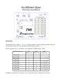
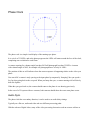
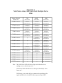
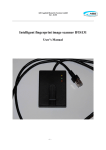
The Kitchen
Sync
Versatile master sync generator and tester
Preliminary User Manual
The Kitchen Sync
Preliminary User Manual
Overview
The Kitchen Sync is a small ( 5” x 4” x 1” ) unit that generates a variety of phase-accurate signals for
synchronizing cameras, 3D rigs, and motion control systems together.
This box generates all 17 of the hi-def video standards of SMPTE 269M / 274M.
SMPTE Frame rate
720P
1080P
(SMPTE 296M) (SMPTE 274M)
1080I
(SMPTE 274M)
60.000 FPS
√
59.940 FPS
√
50.000 FPS
√
30.000 FPS
√
√
√
( 60.000 fields )
29.976 FPS
√
√
√
( 59.940 fields )
25.000 FPS
√
√
√
( 50.000 fields )
24.000 FPS
√
√
√
( 48.000 fields )
23.976 FPS
√
√
√
( 47.952 fields )
In addition, it generates a 50% square wave at any speed between 1.000 fps and 99.999 fps.
The box also supports visual aids for checking adjusting sync and phase in the field without specialty
tools like oscilloscopes and waveform monitors.
Outputs:
The Kitchen Sync has 5 outputs. All outputs are phase-accurate with each other.
Tri-Level Sync:
(2 ports)
Standard 0.6V tri-level sync for most hi-def cameras operating at video rates.
This output operates whenever a “valid” sync speed is selected. When an offspeed rate is specified, this output goes dark.
HD-SDI Sync:
(2 ports)
Standard HD-SDI signal for hi-def cameras requiring a digital sync input.
This output operates whenever a “valid” sync speed is selected. When an offspeed rate is specified, this output goes dark.
50% Square Wave:
(2 ports)
This TTL/LVTTL compatible output drives cameras which require a once-per
frame signal, such as some specialty video cameras, many film cameras, and
specialty interface devices such as “Barton Boxes”
This output operates at all output speeds.
If necessary, the voltage level on this output is selectable between 3.3V and 5.0 V
via a jumper inside the box on the bottom of the board, however, since 3.3V is
high enough to be a valid signal even in 5V systems, it can usually be left in the
3.3V position.
Moco Sync:
This TTL level output is intended to provide a 1PPF timing signal to motion
control systems.
This output operates at all output speeds.
In order to keep the moco electronics and the video electronics from interfering
with each other or generating ground loops, this output is electrically isolated
from the rest of the box.
Phase Clock:
This output drives the dedicated phase clock display.
This output operates at all output speeds.
Inputs:
Power:
Apply 8 to 24VDC. Load is appx 190mA@ 8V, 110mA @ 24V.
Controls and Indicators:
Power LED:
Does pretty much what every other power LED on Earth does.
Output FPS:
Selects the basic output frame rate, from 1.000 to 99.999FPS, in
.001 frame increments. Basic accuracy, including oscillator drift, is
+/- 3ppm from 0°c to 40°c, after a one-minute warm up.
Video Format
3-postion slide switch which selects video format, 1080p, 1080i or 720p
Moco Phase:
Shifts the motion control phase relative to the other phase outputs, in
order to better center the moco phase with the cameras.
Each click is 1/10th of a cycle, or 36°
Valid Video:
This LED lights up to indicate that a valid video rate or multiple video rate has
been selected. See below.
Valid Video rates:
Although the sync box will run at any rate from 1 to 99.999 fps, valid HD video is tightly defined and
can only be generated at 5 specific rates from 23.976 to 30.000FPS for 1080 formats, and 8 specific
rates from 23.976 to 60.000FPS for 720P format.
When a valid video rate and format combination is selected, the Valid Rate LED lights up solid to
indicate that the box is generating video sync at the selected frequency.
Semi-Valid and Multiple Video rates:
In addition to the basic video rates, there are situations where a valid video rate cannot be generated,
but a video rate that is a multiple of the frame rate might be useful.
For example, a common situation has an effects shot that uses a high-speed master camera, but
incorporates several lower-speed witness cameras. It would be nice if everything can stay in phase, and
at certain speeds, where all the rates are multiples of each other, this is possible.
Say, for example, you have a master camera at 72FPS. The box can make a 72FPS square-wave, but
cannot create a 72FPS video signal since no such thing exists. It will, however, search for a standard
that is a multiple of the main rate, and generate that speed, if possible.
In this case, all video formats support 24 fps, so the box will create a secondary video sync at 24FPS.
When generating a multiple frame rate, the Valid Frame Rate LED will blink to indicate something is
amiss.
When the box can find no multiple speed, the video sync outputs will go dark. See appendix A for a list
of Valid and semi-valid video rates
Phase Clock
The phase cock is a simple visual display of the running sync phase.
It is a circle of 32 LED's, and as the phase progresses the LED's will rotate around the face of the clock,
completing one revolution for each frame.
A camera exposing for a shutter angle less than 360° will photograph less than 32 LED's. A camera
with a shutter angle of 180°, for example will photograph an arc of only 16 LED's.
The position of this arc will indicate where the camera exposure is happening relative to the video sync
phase.
You can tell if a camera is truly syncing to the input phase by temporarily “bumping” the sync speed a
few fps, then going back to the set speed. When you bump the sync, a camera running wild will slowly
drift out of phase.
When the sync goes back on, the camera should return to the phase it was showing previously.
In the case of a 3D system with two cameras, both cameras should show the exact same phase sector.
Audio Sync
The phase clock has a secondary function, it can be used to set audio delay timings.
Typically on a film set, audio and video take two different processing paths.
With the advent of digital video, many of the video processing electronics used on-set now add one or
more frames of delay per box. This effect is especially pronounced with 3D systems which typically
use many layers of processing to do flips and monitor packing.
As a result, a significant audio/video skew can develop by the time both signals reach the video village.
The phase clock can be used as a tool to determine this delay.
In this application, flip the small select switch on the face of the clock from “phase” to “audio”. The
clock will then start an automatic 1 second countdown sweep, flashing and beeping at exactly 12:00.
Given these two synchronised events, the audio delay can then be set so that the sound and picture
arrive at the monitors in-sync.
Motion Control Sync
In a Kuper motion control system, once camera sync has been established, the phase clock may used to
establish moco phase.
For this application, the motion control system is synchronized to the sync generator with the moco
phase output, which is a once-per frame TTL pulse. The moco sync pulse is electrically isolated from
the camera sync pulses and power supply.
The phase clock is driven by the motion control with the moco interface box.
In the Kuper, the user should determine a spare axis, and set it up to drive the interface box as though
the box were a motor channel.
Use 256 pulses per frame. You may have to experiment with direction to find out which way is forward
(clockwise).
Create a long move, say, 10,000 frames, and program a linear move to go exactly 1 unit per frame.
( In other words, the first keyframe is exactly 0,0, and the second keyframe is exactly 10000, 10000 )
Zero both the Kuper axis and interface box and run the move. (The phase clock will not run backwards
during preroll The “zero” light on the front of the box will blink to warn you that the clock is not
responding. The clock will “catch up” as soon as the move rolls forward and the phase goes through
zero.)
If the camera is photographing a shutter angle less than 360°, you will see a sector of LED's.
With the Kuper phase angle set to its 180° default position, use the “moco phase adjust” switch on the
sync generator to rotate the LED sector to center on 6:00.
6:00 is the center of the Kuper frame, and now corresponds to center shutter open.
For more accuracy, you can then use the sync phase adjust in the Kuper to tweak the display to exactly
6:00.
Appendix A:
Valid frame rates, and Semi-Valid Multiple frame
rates
Master Selected
Frame rate
720P
1080P
1080I
SELECTED
SELECTED
SELECTED
96.000
frames/sec
Generates
24.000 frames/sec
Generates
24.000 frames/sec
Generates
48.000 fields/sec
95.904
frames/sec
Generates
23.976 frames/sec
Generates
23.976 frames/sec
Generates
47.952 fields/sec
75.000
frames/sec
Generates
25.000 frames/sec
Generates
25.000 frames/sec
Generates
50.000 fields/sec
72.000
frames/sec
Generates
24.000 frames/sec
Generates
24.000 frames/sec
Generates
48.000 fields/sec
71.928
frames/sec
Generates
23.976 frames/sec
Generates
23.976 frames/sec
Generates
47.952 fields/sec
60.000
frames/sec
√
Generates
30.000 frames/sec
Generates
60.000 fields/sec
59.940
frames/sec
√
Generates
29.970 frames/sec
Generates
59.940 fields/sec
50.000
frames/sec
√
Generates
25.000 frames/sec
Generates
50.000 fields/sec
48.000
frames/sec
Generates
24.000 frames/sec
Generates
24.000 frames/sec
Generates
48.000 fields/sec
47.952
frames/sec
Generates
23.976 frames/sec
Generates
23.976 frames/sec
Generates
47.952 fields/sec
30.000
frames/sec
√
√
√
( 60.000 fields )
29.976
frames/sec
√
√
√
( 59.940 fields )
25.000
frames/sec
√
√
√
( 50.000 fields )
24.000
frames/sec
√
√
√
( 48.000 fields )
23.976
frames/sec
√
√
√
( 47.952 fields )
Note: The Valid Video LED will always light solid when the box is
making an exact video frame rate...
Will always blink when the box is making a sub-multiple video
frame rate...
Will always go out when the box cannot make a matching video
signal, and the tri-level and SDI video outputs will go “dark”.