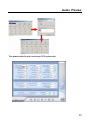
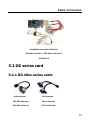
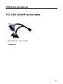
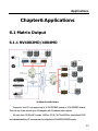
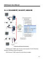
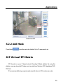
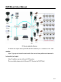
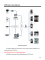
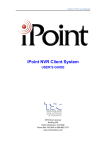
1
WELCOME Thank you for purchasing our product! Before installation, please read this user’s guide carefully and keep this for future references. INDEX Chapter1 Product Description... 6 1.1 General Description ........................................ 1.1.1 Feature ................................................................ 1.2 Technical Specification................................... 1.2.1 NV40XXHC Series ............................................. 1.2.2 DG40xxHC Series.............................................. 1.2.3 DG41xxHC(HF) Series ..................................... 1.2.4 DG42xxHF Series .............................................. 1.2.5 DG4204HD......................................................... Chapter2 Environment II DVR Board User Manual Requirement ............................... 12 2.1 Operating System............................................ 2.2 CPU and Motherboard.................................... 2.3 System Memory.............................................. 2.4 Video Adapter.................................................. 2.5 HDD................................................................. Chapter3 Driver Installation...... 14 3.1 Install NV & DG Card Together .................... 3.1.1 In Windows XP ................................................... 3.1.2 In Windows 7....................................................... III INDEX Chapter4 Audio Preview ........... 27 Chapter5 Cable Connection..... 29 5.1 NV Series Card ............................................... 5.2 DG series card ................................................. 5.2.1 DG 40xx series cable ......................................... 5.2.2 DG 42xxHF series cable ................................... Chapter6 Applications............... 32 6.1 Matrix Output.................................................. 6.1.1 NV4002MD/4004MD ........................................ 6.1.2 DG4208HF/4216HF/4004HD ......................... IV DVR Board User Manual 6.2 Motion Detection & Mask Setup................... 6.2.1 Motion Detection Setup ..................................... 6.2.2 Add Mask............................................................. 6.3 Virtual IP Matrix.............................................. 6.4 Mobile Client................................................... 6.5 POS-DVR System .......................................... Chapter7 Appendix FAQ ........... 42 V Environment Requirement Chapter1 Product Description 1.1 General Description NV & DG Series DVR Boards are professional digital security products using H.264 video and PCM/ADPCM (G.711) audio compression technology. They are designed for real time video & audio capturing with encoding in surveillance system. Different models of NV & DG series cards can be mixed installed and operate smoothly in one PC DVR. 1.1.1 Feature Comply with PCI 2.2 / PCI-E 1.0 standard Support Windows 2000/2003 / Windows XP / Vista / 7, 32 / 64-bit OS Support up to 64 channel input in a PC Support 4CIF preview on any cameras, support 1920x1080 layout. Support dual stream encoding User-adjustable image quality and bit rate User-adjustable video brightness / hue / contrast Build-in motion detect Support OSD, LOGO, and mask settings Support video output (some specific model) 6 DVR Board User Manual 1.2 Technical Specification 1.2.1 NV40XXHC Series NV4004HC NV4008HC NV4016HC Model Video Compression H.264 Input 4/8/16 CH BNC(1.0Vp-p, 75Ω) Preview Resolution 704*576(PAL), 704*480(NTSC) Full-channels D1 with 12/15fps, no sub stream; Encoding Full-channels DCIF/CIF or half-channels D1 with 25/30fps, support sub stream in CIF/QCIF with 25/30fps 48K~900K bps(CIF) per channel Recording 80K~1.5M bps(DCIF) per channel Bit Rate 108K~2.4M bps(4CIF) per channel Audio Input 4 / 8 / 16 Ch BNC (2.0Vp-p, 1Kohm) Audio Compression G.711, 16bit/8KHz, 64Kbps Working Environment -10 ~ +55℃ / 10 ~ 90%RH / 86 ~ 106kpa Power Consumption 3.5W 7.5W 21W Dimension (unit: mm) 152*87 201*101 250*98 7 Environment Requirement 1.2.2 DG40xxHC Series DG4004HC DG4008HC(-E) DG4016HC(-E) Model Video Compression H.264 Standard PAL / NTSC Input 4/8/16 CH BNC(1.0Vp-p, 75Ω) Preview Resolution 4CIF/CIF, Realtime Full-channels D1 with 12/15fps, no sub stream; Encoding Full-channels DCIF/CIF or half-channels D1 with 25/30fps, support sub stream in CIF/QCIF with 25/30fps 48K-900K bps(CIF) per channel Recording 80K-1.5M bps(2CIF) per channel Bit Rate 108K-2.4M bps(4CIF) per channel Audio Input 4/8/16 Ch BNC (2.0Vp-p, 1Kohm) Audio Compression G.711, 16bit/8KHz, 64Kbps Working Environment -10~+55℃ / 10~90%RH / 86~106kpa Power Consumption 3W 7W 11W Dimension (unit: mm) 152.5*93.2 182.5*106.6 257*106.6 1.2.3 DG41xxHC(HF) Series 8 DVR Board User Manual DG4108HC DG4116HC DG4108HF Model Video Compression H.264 Standard PAL/NTSC Input 8/16 CH BNC(1.0Vp-p, 75Ω) Preview Resolution Encoding 4CIF/CIF, Realtime Full-channels D1 with 6 / 7fps, Full-channels D1 half-channels 2CIF with 12 / 15fps / 2CIF / CIF with Sub Stream: N/A 25 / 30fps Full channels CIF with 25/30fps Sub Stream: QCIF with 25/30fps Sub Stream: CIF/QCIF with 25/30fps 48K~900K bps(CIF) per channel Recording 80K~1.5M bps(2CIF) per channel Bit Rate 108K~2.4M bps(4CIF) per channel Audio Input 8/16 Ch BNC (2.0Vp-p, 1Kohm) Audio Compression G.711, 16bit/8KHz, 64Kbps Working Environment -10 ~ +55℃ / 10~90%RH / 86 ~ 106kpa Power Consumption 3W 7W 11W Dimension (unit: mm) 152.5*93.2 182.5*106.6 257*106.6 1.2.4 DG42xxHF Series 9 Environment Requirement DG4208HF DG4216HF Model Video Compression H.264 Standard PAL/NTSC Input 8/16 BNC(1.0Vp-p, 75Ω) Preview Resolution 4CIF/CIF, Realtime Encoding Full-channels D1 / 2CIF / CIF with 25/30fps Sub Stream Recording Bit Rate Video Output CIF/QCIF : 1~25/30fps 48K~900K bps(CIF) per channel 80K~1.5M bps(DCIF) per channel 108K~2.4M bps(4CIF) per channel 1 CH BNC 1CH BNC 1 / 4 / 8 / 9 / 16 Views, support tour display Audio Input 8 / 16 Ch BNC (2.0Vp-p, 1Kohm) Audio Compression G.711, 16bit/8KHz, 64Kbps Working Environment -10 ~ +55℃ / 10~90%RH / 86~106kpa Power Consumption 8W 12W Dimension (unit: mm) 145*93 175* 106.6 Note: The DG4216HF has two video-audio cables. So the DG4216HF has two TV outputs. But only the first TV output (the TV output of the cable that connects to upper interface) is available. 10 DVR Board User Manual 1.2.5 DG4204HD DG4204HD Model Video Compression H.264 Standard 1080P(25,30)/1080I(50,60)/720P(25,30,50,60) Input 4 channel, HD-SDI HD video, BNC Preview Resolution Encoding Resolution Max 1080P(1920×1080), Realtime 1080P(1920×1080), 720P(1280×720), 1080P/4(960×540), 720P/4(640×360), 1080P/16(480×270), 720P/16(320×180) Frame Rate 1~25/30fps at all resolutions Sub Stream 1080P/4, 720P/4, 1080P/16, 720P/16 with 25/30 fps Recording Bit Rate 256Kbps~8Mbps per channel Video Output 1 CH HDMI (1920*1080) or 1 CH VGA (1280×1024) 1/4 display split, Support Tour function Audio Input 4 CH BNC (2.0Vp-p, 1Kohm) Audio Compression G.711, 16bit/8KHz, 64Kbps Working Environment -10 ~ +55℃ / 10~90%RH / 86~106kpa Power Consumption 16W Dimension (unit: mm) 250*106.6 11 Environment Requirement Chapter2 Environment Requirement 2.1 Operating System Supports Windows 2000/2003 / Windows XP / Vista / 7 32&64bit. Windows XP and Windows7 32bit OS are preferred. DirectX OS version should be 8.1 or above. Screen resolution should be 1024*768 or above. 2.2 CPU and Motherboard Intel CPU is preferred, but AMD CPU will also be supported. Motherboards should be based on Intel or AMD chipset. Motherboards from reliable manufacturers such as Intel, Asus, Gigabyte, etc, or specific DVR motherboard such as 945GC. 12 DVR Board User Manual 2.3 System Memory The memory of the system should be 1GB or above. 2.4 Video Adapter Best to use AMD or NVIDIA independent video adapter, or INTEL integrated display unit. Please install the latest official drivers for the video adapters. Video adapter RAM should be 512MB or above. 2.5 HDD Please select hard disks from reliable manufacturers. Some hard disk or RAID card supports Intelligent Power feature that helps to save power by reducing the RPM (spinning speed of the hard drive). Please disable this feature, because if the RPM gets reduced, the HDD read/write speed will be lowered and the recorded data cannot be written onto the hard disk fast enough. This will create problems such as video distortion and frame lost. 13 Driver Installation Chapter3 Driver Installation The DVR Server installer is packaged with drivers for different OS and card models. Please select the appropriate driver accordingly. Driver Directory After you installed the card into an empty PCI or PCI-E slot, turn on the PC to start Windows. Windows Hardware Wizard will detect the newly installed card and this panel will appear: 14 DVR Board User Manual There are two ways to install the driver: follow the wizard to install the driver manually, or ignore the wizard and install the driver by using DriverInstall.exe . If you choose the first way, please go to step 1, otherwise, start from step 4. Note: the first way is preferred, especially when both the DG and NV series card are installed in one PC. “DriverInstall.exe” might NOT be available on selective OS for some board models. Driver Install Steps: 1. In the New Hardware Wizard page, select “Install from a specific location (Advanced)”, then click next to choose the driver to install. 15 Driver Installation 2. Locate the driver folder and select the correct driver to install. The driver will show up in the compatible hardware window. Click next. A warning dialog box will popup; click “Continue Anyway” to finish the driver installation. 16 DVR Board User Manual 4. You can also run the DriverInstall.exe to install the driver. Install driver for DG Series Board by DriverInstall.exe 17 Driver Installation Install driver for DG Series Board by DriverInstall.exe Note: For DG series board, when the drivers are installed completely, system will inform you to restart the computer, please do it. There is no such a need for NV series board. 5. Open the device manager to check if the driver is correct. Driver for NV series boards can be found under the directory “Sound, video and game controllers” while driver for DG series boards can be found under the directory “DGSeriesCard”. Please make sure that the total number of drivers should equal to the total number of DSPs on all installed cards in the PC. If the board cannot be identified by the DVR Server software, please open the device manager to check the driver. If the driver is not on available status, please right click on the driver and select update. Then follow the previous steps to install the proper driver manually and restart the computer. If this is not work, please contact the technician. 18 DVR Board User Manual Drivers shown in the device manager 3.1 Install NV & DG Card Together NV and DG series cards can operate together in one PC as long as all drivers are installed correctly. There are installation differences between Windows XP and Windows 7. 3.1.1 In Windows XP In this example, let us assume that there are 4 cards inserted in the system: DG4108HC in the first PCI slot, DG 4004HC in the third, NV4208HFV in the fourth and NV4004HC in the fifth one. Please cancel New Hardware Wizard for all cards. Then open device manager. You 19 Driver Installation will see the interface as below. Check and update the drivers In windows XP, right-single-click on the driver, then the driver location will be described as below (marked with red box). There is “PCI Slot X” displayed here so that you can locate different drivers according to the slot number. 20 DVR Board User Manual The driver shown as below is incorrect because it is the NV4004HC board inserted in slot 5, not DG board. 21 Driver Installation You need to uninstall it and install the correct driver for the card in that slot. Then, single-right-click and select “Scan for hardware changes”. Follow the Hardware Wizard to install the proper driver manually. 22 DVR Board User Manual When all drivers are installed correctly, you can see the interface as below: 3.1.2 In Windows 7 Windows 7 will install drivers for most new hardware automatically. This process is good only if there is one type of new card installed in the system. If there is a mix of new DG and NV cards, Windows7 will only install one type of driver to all of these cards. This can be problematic and cannot be easily sorted out afterwards. Even if you single-right-click on one of the drivers’ names and enter its properties in Device Manager, it will show only its location (marked with red box), but there is no “PCI Slot X” displayed and you cannot assign the right drivers based on the card slot number. 23 Driver Installation To make the different series cards work together in Windows 7, please follow this: 1. Install only one model of card into the PC, then, start up the computer. Then open the device manager to check if the drivers are installed correctly. Update the drivers if they are not proper ones. Please delete the wrong driver and check the option “Delete the driver software for the device” first. Then scan the hardware change and update the driver. 24 DVR Board User Manual 2. Shutdown the computer and remove the card(s) inserted in step 1. Insert another model of card(s) into another slot(s) of the PC. Please do not re-use slots that are allocated in step 1. Start the computer and repeat step 1. 3. Repeat step 1 and 2 until all cards models have their drivers installed. 4. Insert all the cards into the corresponding slots where the drivers are allocated. For example, put the DG4008HC back to the same first slot when you install its driver. Then, re-start the computer. Different models of cards will work together in windows 7. 25 Driver Installation 26 DVR Board User Manual Chapter4 Audio Preview The audio cable will be found in the package case of the board. Please connect the audio cable as follows: Note: When there is no preview sound, double click the volume control in the taskbar, open the properties dialog box, and enable AUX control. 27 Audio Preview Then please enable the audio monitoring in DVR system setup. 28 DVR Board User Manual Chapter5 Cable Connection 5.1 NV Series Card 4/8 CH board cable 16 CH board cable VID1~VID4: Video input VID1~8: Video input AID1~AID4: Audio input AID1~2: Audio input Each 16 CH board’s cable has 8 channels video input and 2 channels audio input. There is a separate cable for the rest 12 channels audio inputs (audio 5-16). You need to connect the audio cable to port JP2 on the DVR board card. Take NV4216HC for example, the Video/Audio connection should be as below: 29 Cable Connection Audio&Video connection for 16CH board DB1:Video1~8, Audio1~2 DB2: Video9~16, Audio3~4 JP2:Audio5~16 5.2 DG series card 5.2.1 DG 40xx series cable 4/8CH card cable 16CH card cable VID1~VID4: Video input VID1~8: Video input AID1~AID4: Audio input AID1~8: Audio input 30 DVR Board User Manual 5.2.2 DG 42xxHF series cable VID1~8: Video input AID1~8: Audio input TV: Video output 31 Applications Chapter6 Applications 6.1 Matrix Output 6.1.1 NV4002MD/4004MD NV Matrix Board Work Sketch At present, one PC can support up to 16 NV4002MD boards or 8 NV4004MD boards. That is to say, it can decode up to 64-channels with 32-channel video outputs. All video from NV40xxHC boards, NV60xx (DVS), NV72xx/NV80xx (standalone DVR) and standard-definition IP cameras can be outputted via NV4002/4004MD boards. 32 DVR Board User Manual 6.1.2 DG4208HF/4216HF/4004HD DG42xx Board with Output Port Work Stretch DG4208 has one TV (BNC) output. The video can be outputted to TV with VGA interface. Multi splits 1/4/8/9 and tour function are supported. DG4216 has two TV (BNC) outputs. But only the first port is available. 33 Applications Multi splits 1 / 4 / 8 / 9/ 16 and tour function are supported. DG4204HD card has one HDMI (1920*1080) output and one VGA (1280*1024) output. It supports 1/4 split view and tour function. These cards can be mixed installed in one PC, and the outputs are configured independently. That means each card can only output its own cameras. 6.2 Motion Detection & Mask Setup 6.2.1 Motion Detection Setup Press button to open the motion setup GUI. Motion Detection Setup GUI 34 DVR Board User Manual By default, the entire screen is set as “motion-detection-area” when there is a green border around the image. You can set up to 12 motion detect areas for each channel by drawing rectangles on the video window. You can control the sensitivity of motion alarm in the motion detect area by adjusting the sensitivity value and motion value. Smaller value means higher sensitivity. The default value of Sensitivity and Motion are 2 and 5%. Sound Alarm Enable Sound Alarm and select a value from the drop-down list for the alarm. When the sound is detected over the value you selected, the software will take it as a motion alarm. Of course you need to connect an audio microphone for this option. Motion Link to PTZ The motion alarm is able to link up different assigned zones with preset(s) of PTZ camera(s) (both IP and Analog speed dome). You need to set the linked PTZ camera and its preset number for each detect zone. 4/8/16/32/64/128 zones can be set. In the previous diagram, 4 zones were set up; zone 03 is linked up with preset 9 of PTZ camera 01. Any motion detected within zone 3 will trigger and command PTZ camera 01 to go to preset 9. The assigned zones have to be within the pre-set “motion-detect-area”. 35 Applications Motion link to PTZ 6.2.2 Add Mask Press button to set the area to be shielded. Up to 12 areas can be set. 6.3 Virtual IP Matrix PC Decoder is a pure IP based network Decoding & Matrix platform. By using this platform, user can decode all IP videos, such as video from Netvision DVR, standalone DVR, DVS and IP cameras by distributing computers and output all videos to VGA monitors as matrix. 36 DVR Board User Manual PC Decoder Application Structure TV client can output videos (both SD and HD resolution) to a maximum of 24 VGA monitors. Up to 16 groups can be set for each monitor. User can set view partitions and cameras to be decoded (and output). Up to 16 partitions can be set for each VGA monitor. For more details, please refer to Manual of PC Decoder (for NVR Client) 37 Applications PC Decoder Work Sketch (NVR Client) 6.4 Mobile Client PDA such as Symbian, Windows Mobile, BlackBerry, Android and iPhone/iPad can connected to the DVR or NVR s/w for viewing and controlling PTZ by mobile client. 38 DVR Board User Manual Mobile Client Work Stretch For Windows Mobile and Symbian phone users, please download mobiledvr.jad and mobiledvr.jar from the DVR Server. Note: Windows Phone 7 is not supported at present. For BlackBerry users, please download BlackBerry.jad from DVR Server. 39 Applications For Android phone users, please search and download “netdvrviewer” from Android Market. For iPhone and iPad users, search and download “MobileClient” or “Net PCdvrviewer” from Online App Store. Note: The App “Net PCdvrviewer” supports 4 split viewing. For all the NV series devices (including DVR board, DVR, standalone, IP cameras), users can only preview and control PTZ with “Net PCdvrviewer”. For all the other devices, users can also playback and download the record remotely with “Net PCdvrviewer”. For details on how to use mobile client, please refer to our mobile client user manual. 6.5 POS-DVR System Both analog and IP cameras are supported in POS system. Any POS devices that send plain-text data based on ASCII code through serial port (RS-232-C) or network (TCP/IP). The POS-DVR surveillance system has the following specifications: POS Text Overlay with Video: Display/hide transaction information over cameras’ video real-time; customize text positions and font, high light keywords. Multi-Channels POS Search: Up to 4 channels search and playback with transaction data at the same time. Count and filter user-defined special transaction message. Event Monitor: Store all transaction data in Microsoft Access format for statistics. User can click text message to view corresponding video record. Alarm: output alarm and email notification. For more details, please refer to our POS User Manual. 40 DVR Board User Manual POS Application Work Sketch 41 FAQ Chapter7 Appendix FAQ 1 Driver is on unavailable status when checking it in device manager after installing the driver with DriverInstall.exe. Solution: Uninstall the unavailable driver and re-installed the driver manually. Then restart the computer. 2 HDD Calculator Solution: Before be the DVR Server is building, you can get a reference from the tool HDD Calculator. 42 DVR Board User Manual According to the camera amount, record resolution and image quality, the tool will give a maximum and an average disk space requirement for all cameras with Normal Record. When the DVR is built and you have assigned the disk for storing record by disk manager, the DVR software will be able to estimate how long of record the DVR Server can stored according to DVR system, the camera settings and the disk space. Right-Single-Click on the preview GUI and select “Record Time Calculate”, you will get these informations: total disk space for recording, instant and average bit rate of each channel, currently how many hours of video record the DVR has stored and estimated hours of video the DVR can store if keep current settings. For details about the Record Time Calculate, please refer to the DVR Server User Manual. 43 FAQ 3 PC configurations for DVR Server Solution: Different requirement for DVR (including the number of channels, resolution and frame rate for each camera, enable/disable sub stream and recording type) will require different PC configuration. If you are not familiar with DVR system or you have no any existed familiar system for reference, please contact the technician for the PC configuration according to your specific requirement. 44